This week was a very fantastic week I loved it so much I learned many new, useful and interesting things it is really the most joyful week from the beginning of the Academy. I'm very happy. Basically in this week we have to desgin a mold, then produce it by CNC machine, then cast an object through the mold.
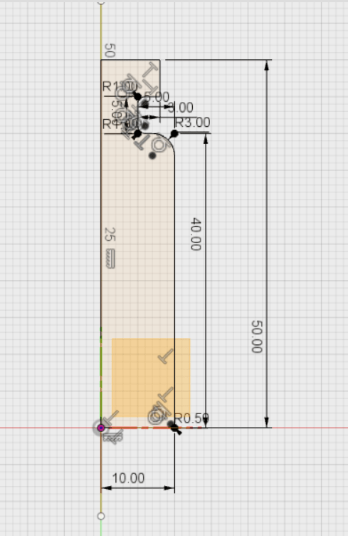
I desided to desgin a 3D mold for a small vial. Start by drawing the shape of the vial using
![]() software. Firstly, the sketch looks like:
software. Firstly, the sketch looks like:
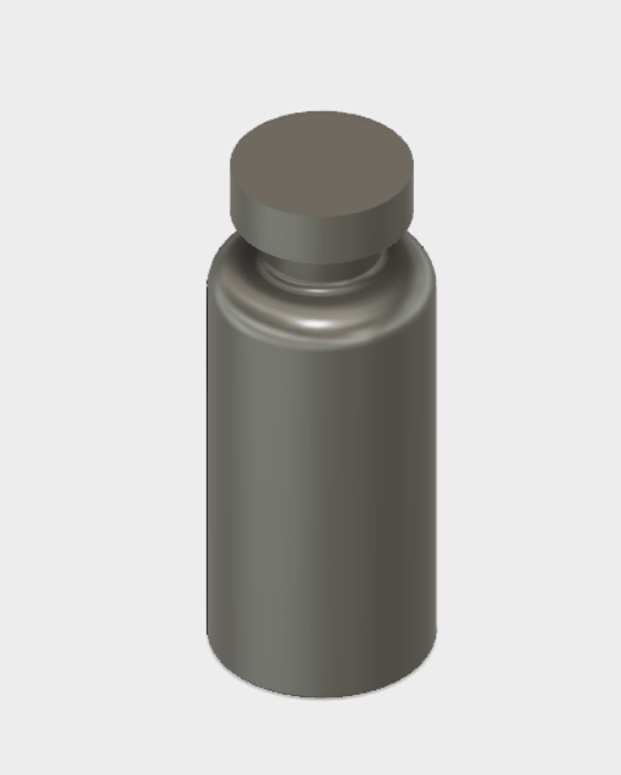
Then Revolve the sketch to see the final shape of my vial
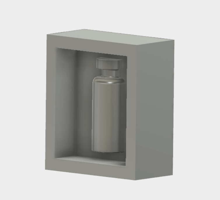
Draw a sketch with the same dimensions of the wax box which I will use to made my mold . The dimentions I have 180mm X 78mm X 38mm so I decided to divide it into two pieces to mill the molds of the two faces of the vial at the same box 'always I love saving resources'
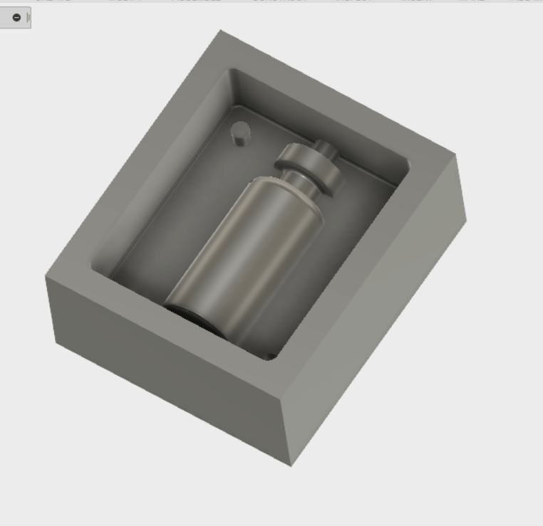
The mold looks like
Add a hole at the top to pour material from it, and also at the buttom to let the air go ut from the mold cave, and add a hole and pin to fix the two mold sides togethor.
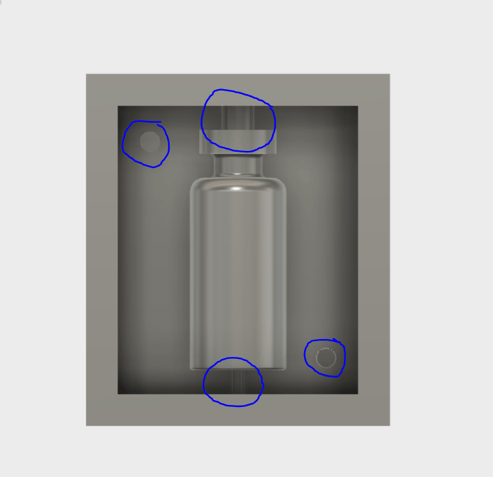
Add some fillets to remove the mold easily. The final model of the mold
To produce a 3D object you need two molds one for each half of the object. Fortunately, the second side of the model is exactly the same as the first part, but the only different is the place of the hole and the pin. Now save molds as .STL
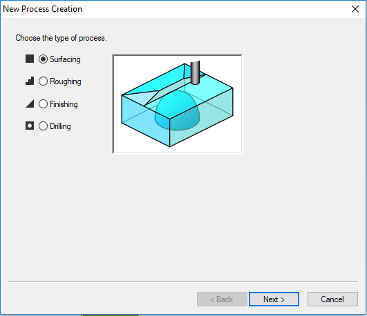
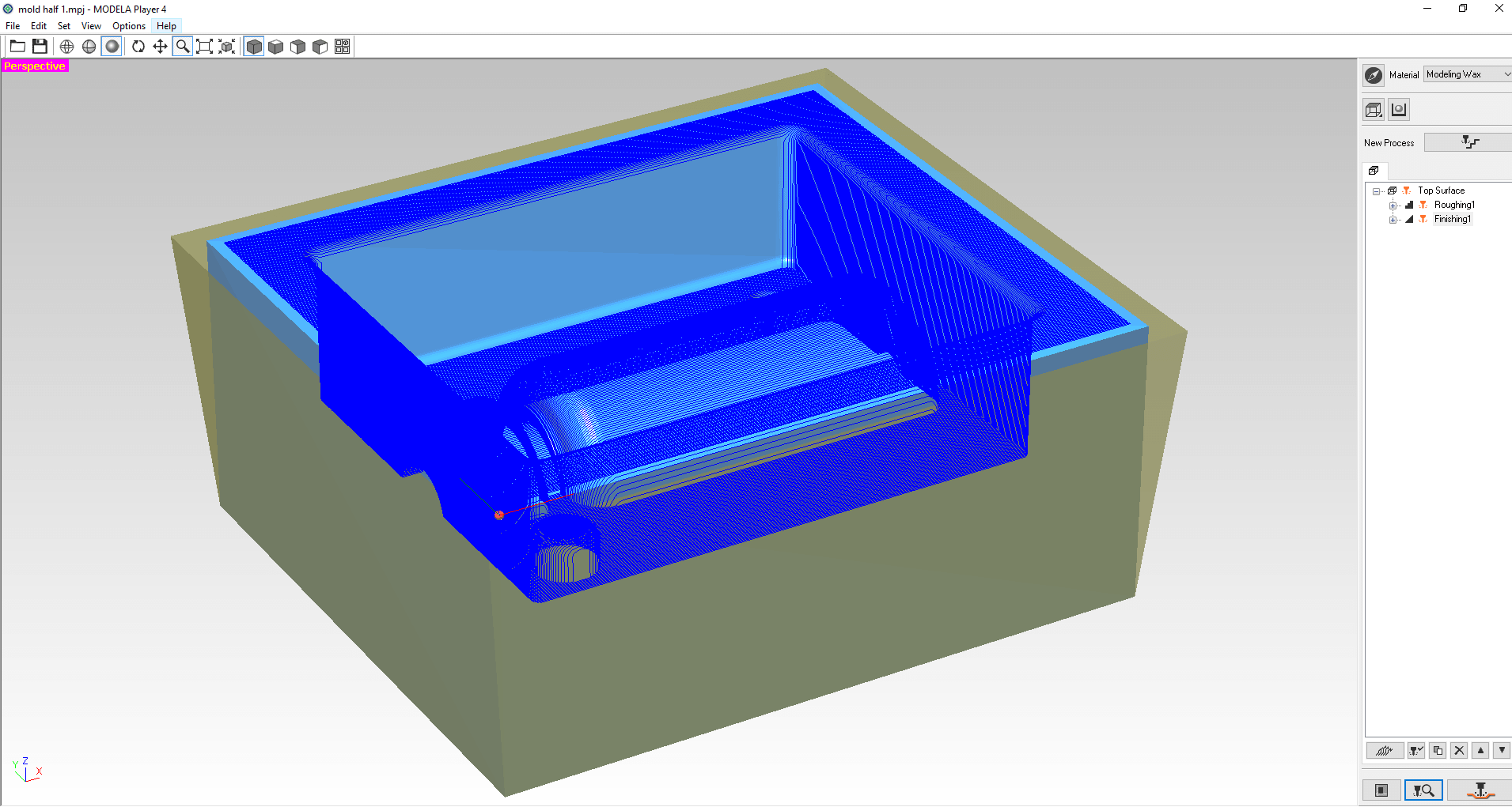
The next step after completing the mold design is to make the settings to control the toolpath which will cut the mold CAM 'Computer Aided Design". I used MODELA Player 4 software which is a 3D CAM software from ROLAND company. I made three jobs to fabricate each side. First one was Surfacing to level the surface of the wax box. Second wasRoughing to make the shape but in low quality. The final one was Finishing to make the final shape.
Start by inserting the design in STL format into MODELA Player 4
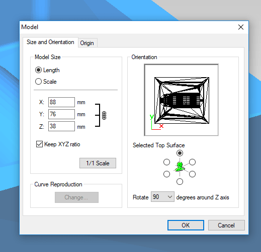
Now, define X and Y axes and set the origin point location as shown:
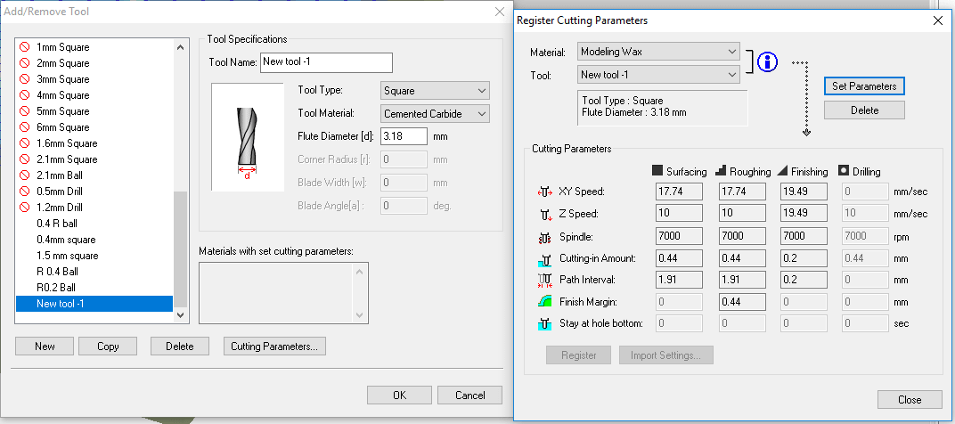
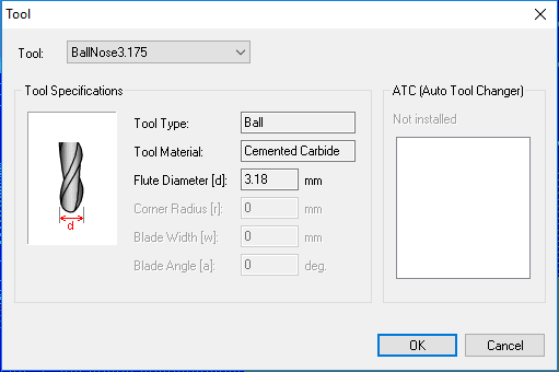
When I see the tool list in the software all of them is in millimeters and we used a 1/8'' for both Flat end mill and ball nose
tools so I manually defined these tools by selecting Add new tool from Options with these parameters:
Press New process and start with a surface operation by following these steps
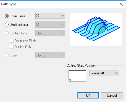
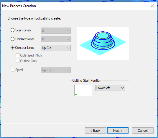
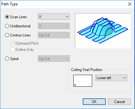
In the following settings screen you can select Scan Lines: defines the movement direction of the machine while surfacing. I choose an X line. Because I think it is better for my design ( I put my vial horizontally on the wax box so X line scan will move parallel to design lines. If I choose Y it will be perpendicular ). Other options do not depend on the axis direction. for example in Contour Lines the cutting tool will move 'around' design lines with certian offset. Also on this screen you can define the job starting point. I selected it in the lower left the same as my origin.
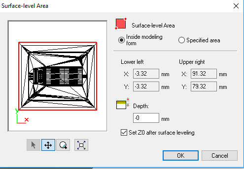
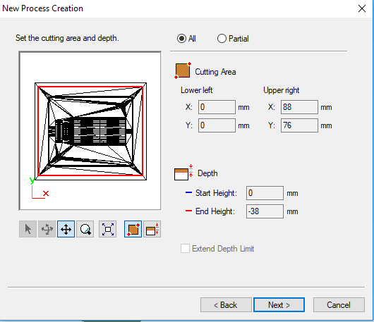
In the next settings screen you can select the surface-level area using an offset from your design or a specified area. Also, you can let the machine reset the Z axis Zero after surfacing complete.
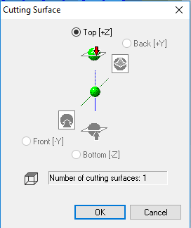
In the next settings screen you can set the cutting surface. I choose Top Z+ because the cutting tool in our machine is fixed on Z axis.
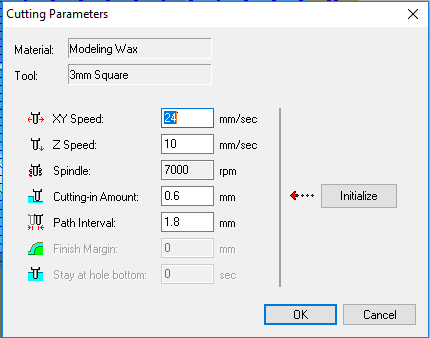
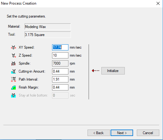
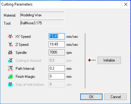
Cutting Parameters defined in the next screen. First when I select the used Material and the Tool the software automatically generates a default setting. I didn't change them. These settings are:
XY speed in mm\sec: when it increases the surface finish quality will decrease.
Z speed in mm\sec: the Z axis down movement speed.
Spindle in rpm: Cutting tool rotation speed when it increases the surface finish quality will increase.
Cutting- in Amount in mm: the depth of cut the tools move each time.
Path interval in mm: the overlap distance between two lines.
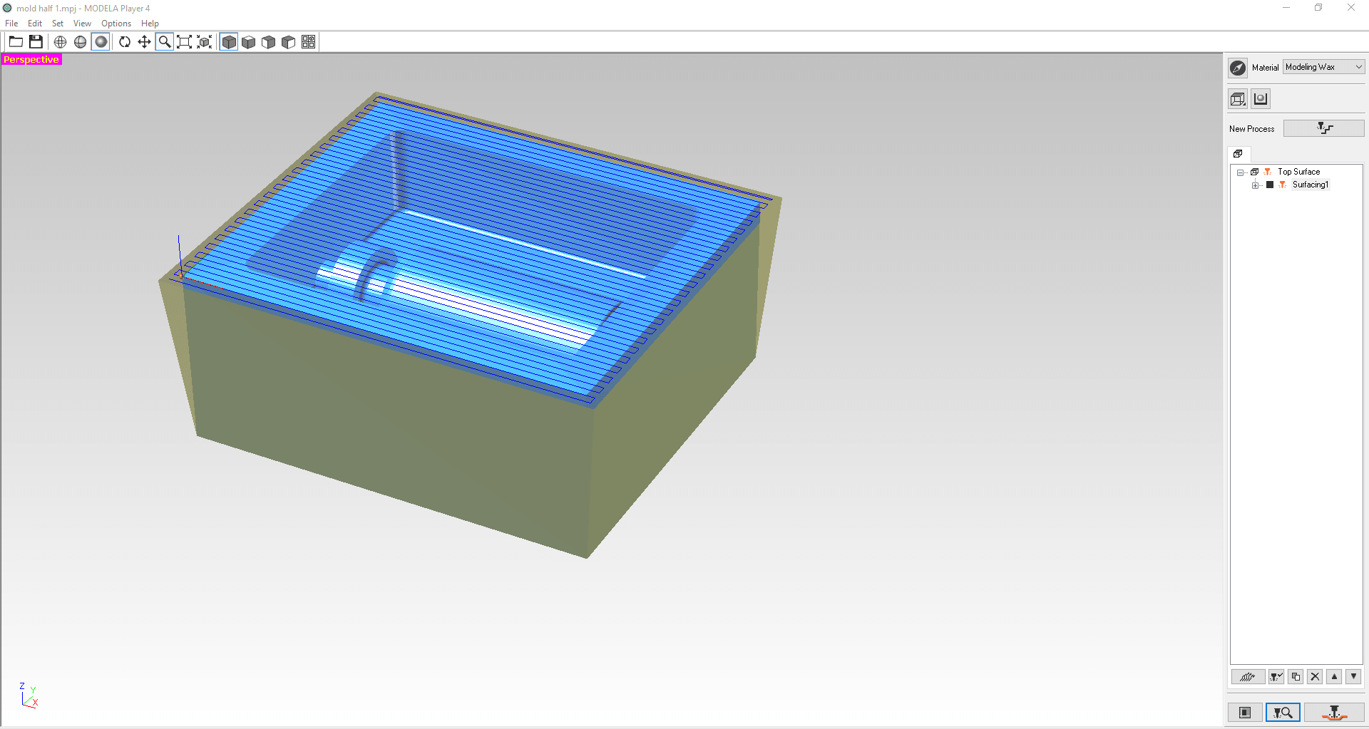
After selection complete the surface operation looks like
Now you can press on  to see simulation of the movement of the tool. Then press
  to save the G-code on a file or to sent it derictly to the Roland machine interface software and automatically start cutting.
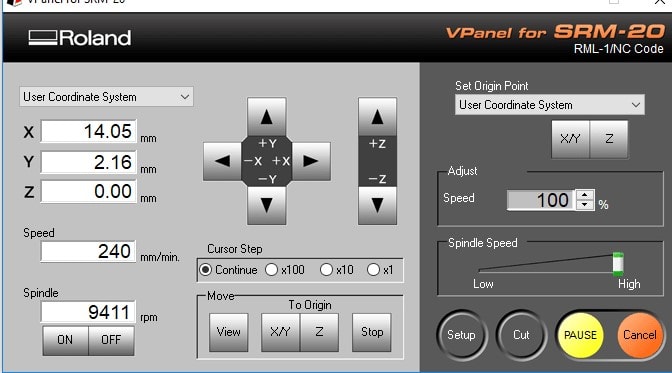
Then fix the wax box on the Roland machine bed and place the 1/8'' square end tool on it's place.Also set origns of X,Y and Z axes as explained in electronic production week. This is how machine looks before start:
Then move to the interface software VPanel for SRM-20 press on Cut and select the saved file then press Output.
To save time while machine working I prepare settings for next operations. After surfacing I must made Roughing cut using these settings, which I describe their meaning in the surfacing step.
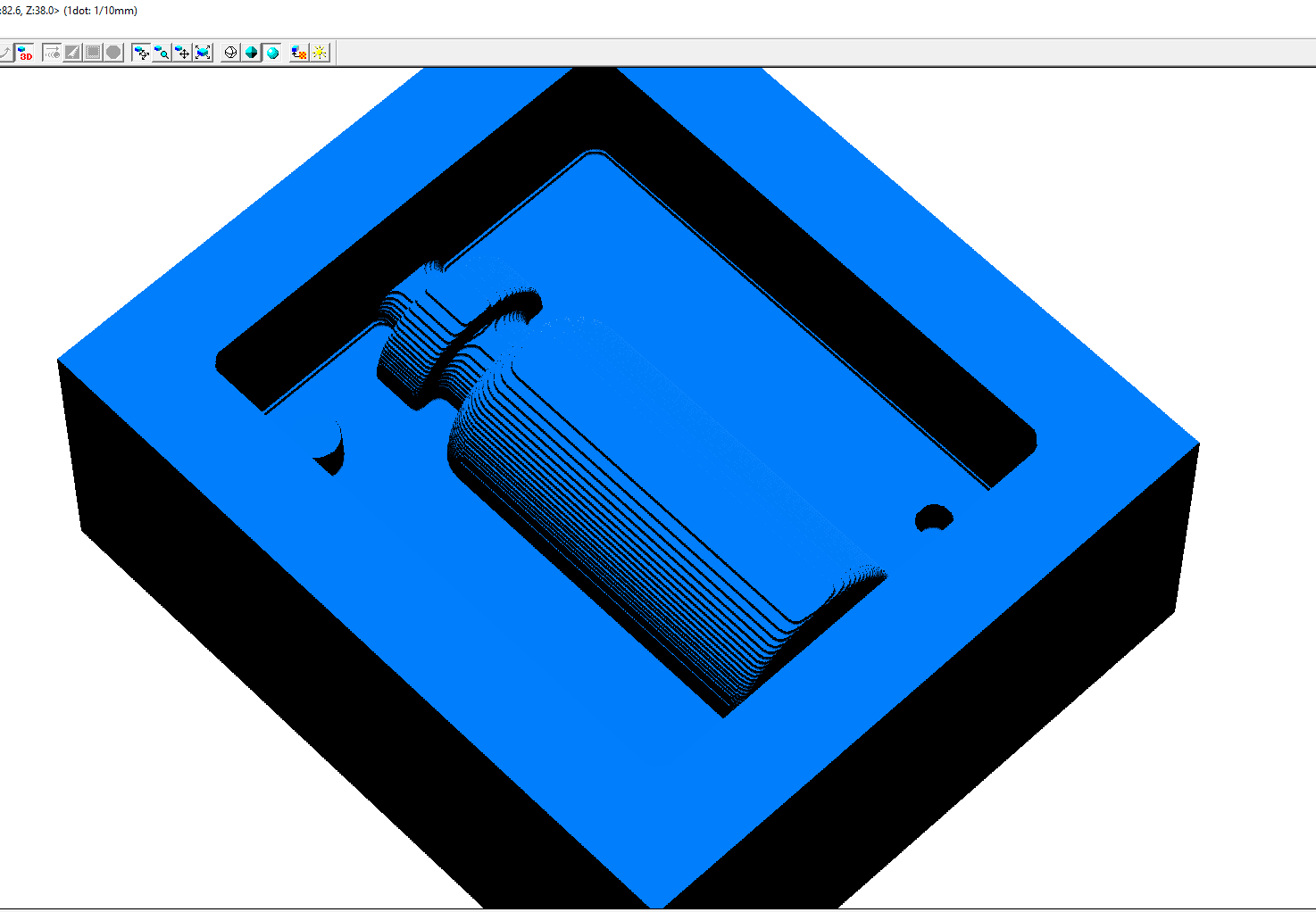
After simulation the mold looks like:
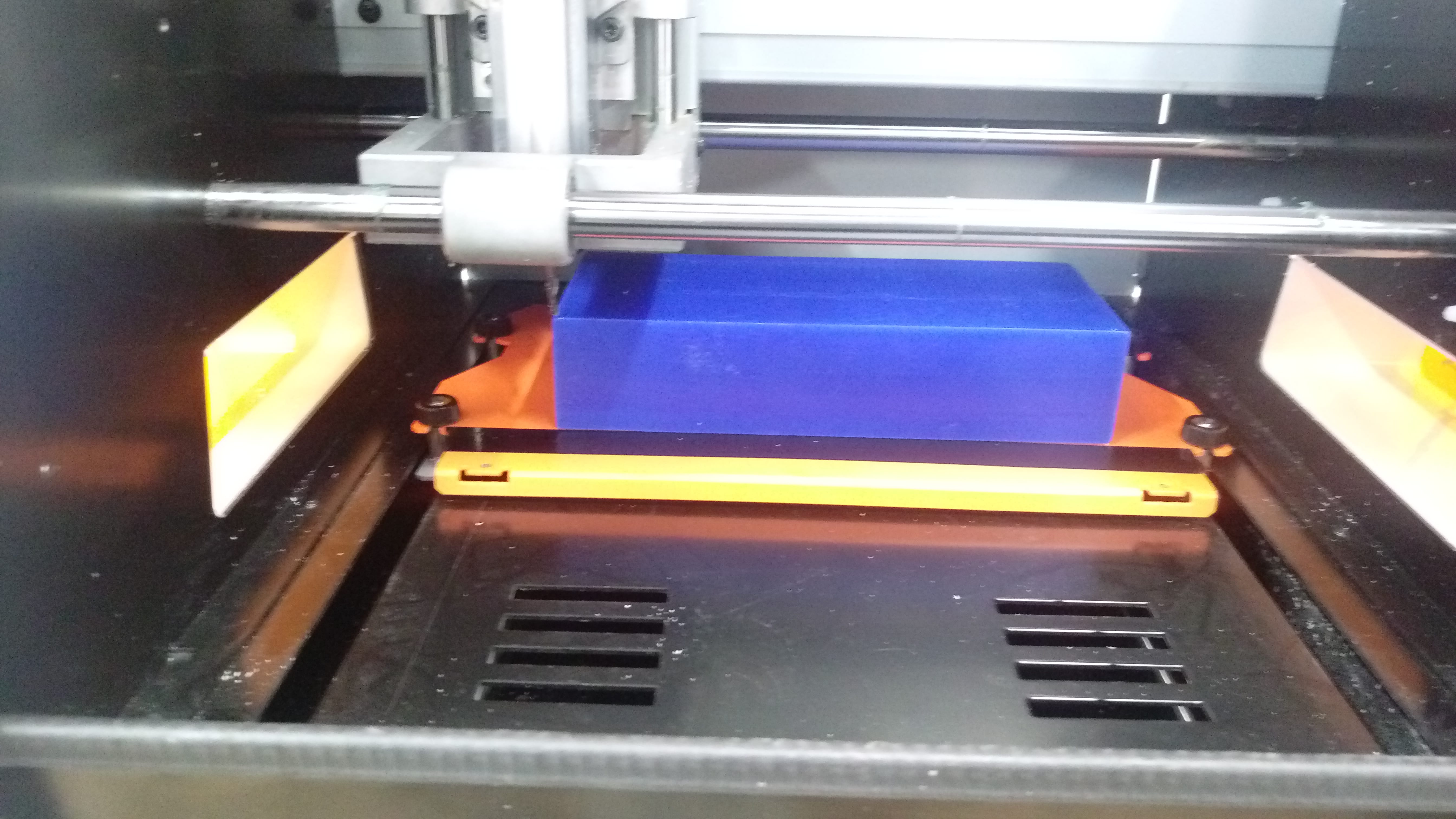
The machine while working
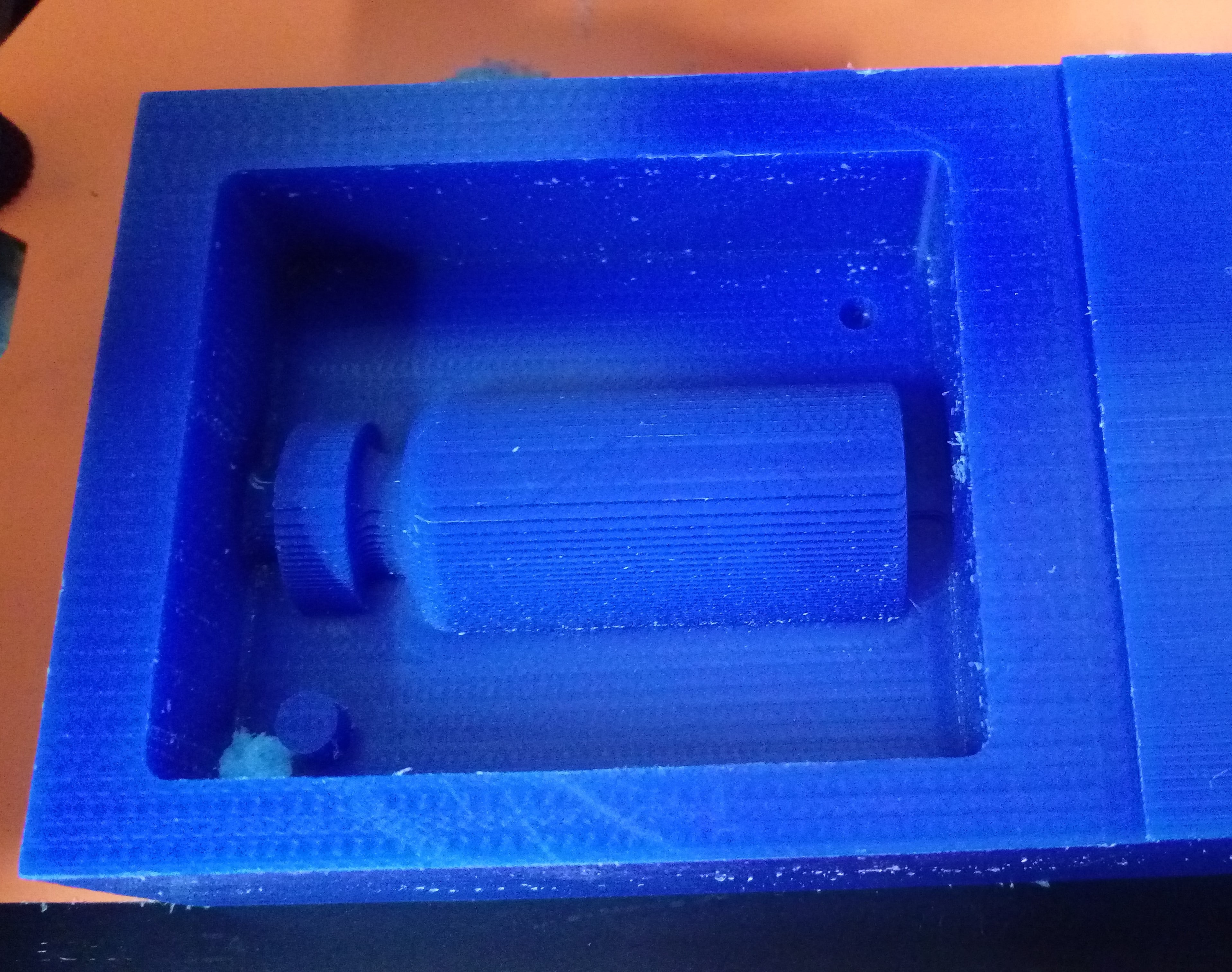
The mold after roughing cut finished
After roughing complete, I changed the tool to Ball nose 1/8''. Modify Z axis zero after changing the tool but keep the X,Y axes orign the same as previous other wise the mold will damage!!.
The ball nose tool using for finishing it produce a smooth surface of a 3D model. The settings used for Finishing job are:
Simulation gave this result:
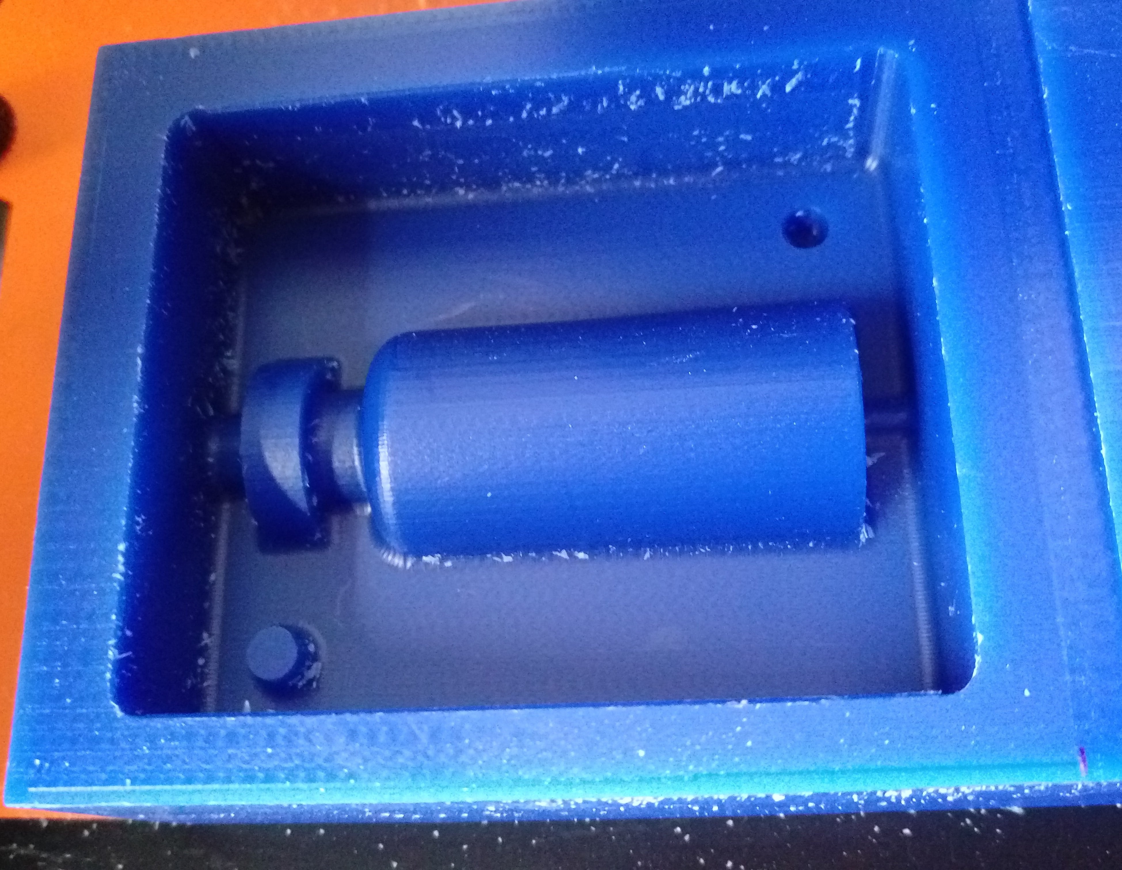
The real model was very smooth I'm very happy with this result
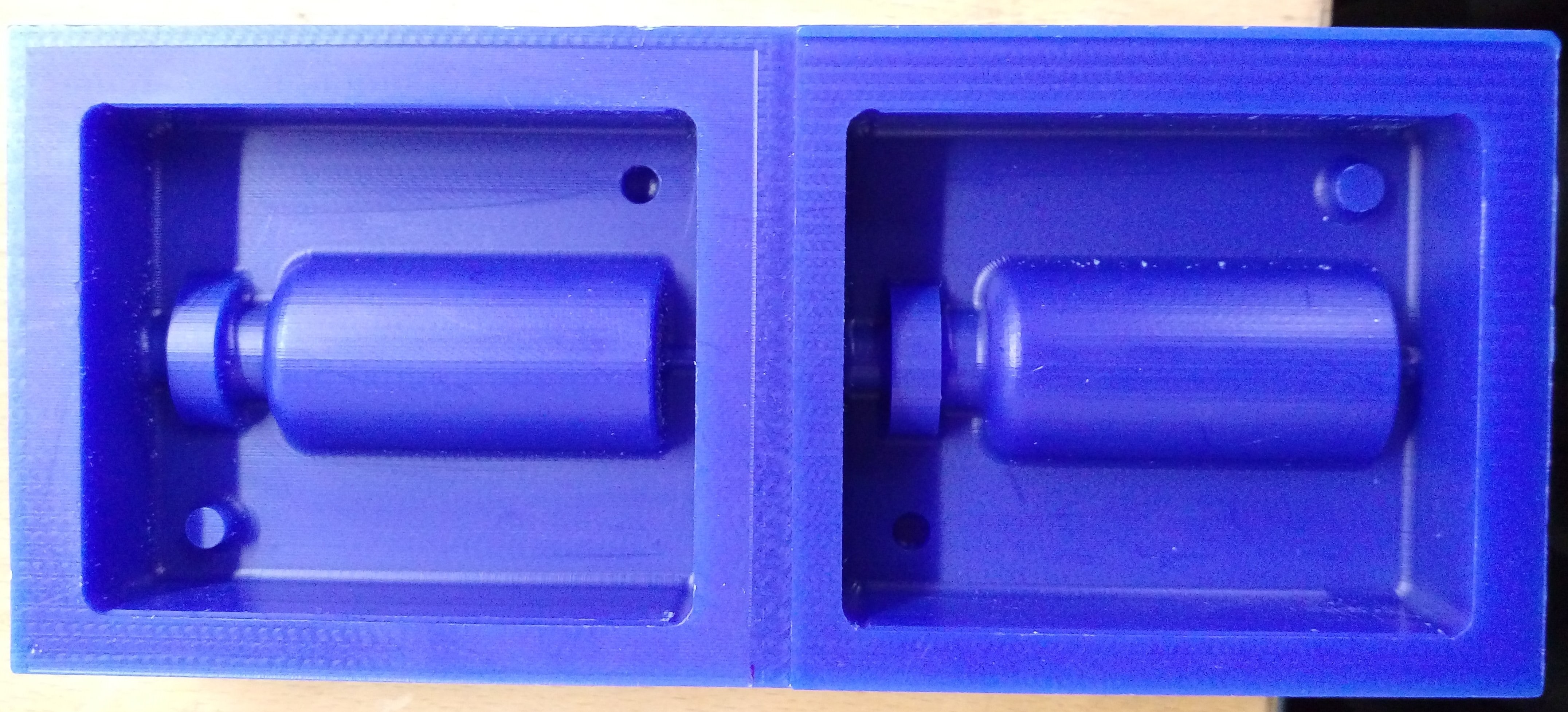
I completed the first side of the model, now I should repeat exactly the same process to do the next side, I could do both sides at the same time but I think it is better to separate them. so now . Set X,Y and Z origns , make settings for the three jobs, generat G-code for each job and cut it. Use the Flat end mill 1/8'' tool for Surfacing and Roughing and Ball noise 1/8'' for Finishing.
This is my final model :)
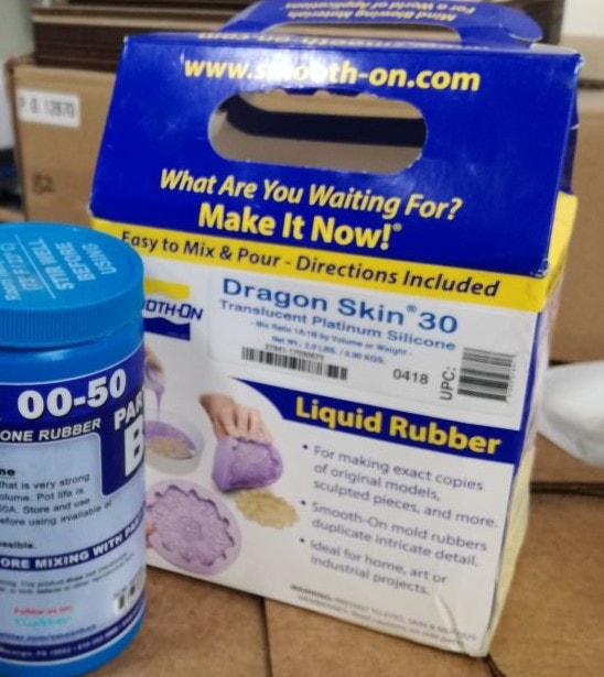
The interesting part starts now, I should cast my mold using the produced wax one. There are many materials in the lab I selected Dragon skin 30 silicones. The figure below has main parameters.
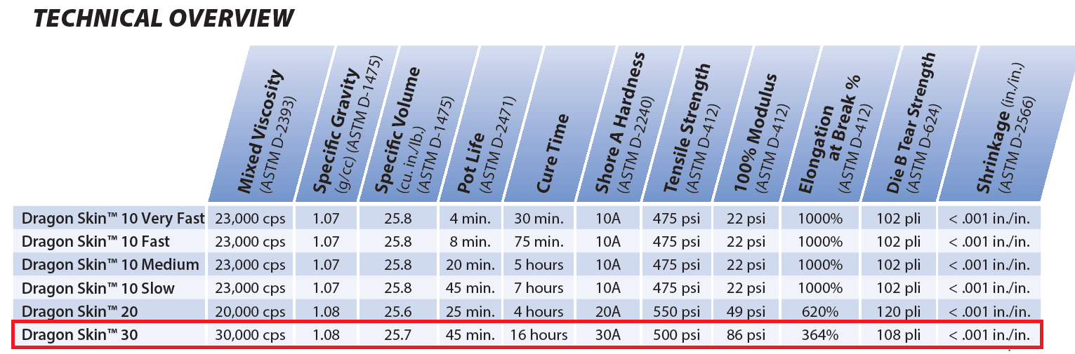
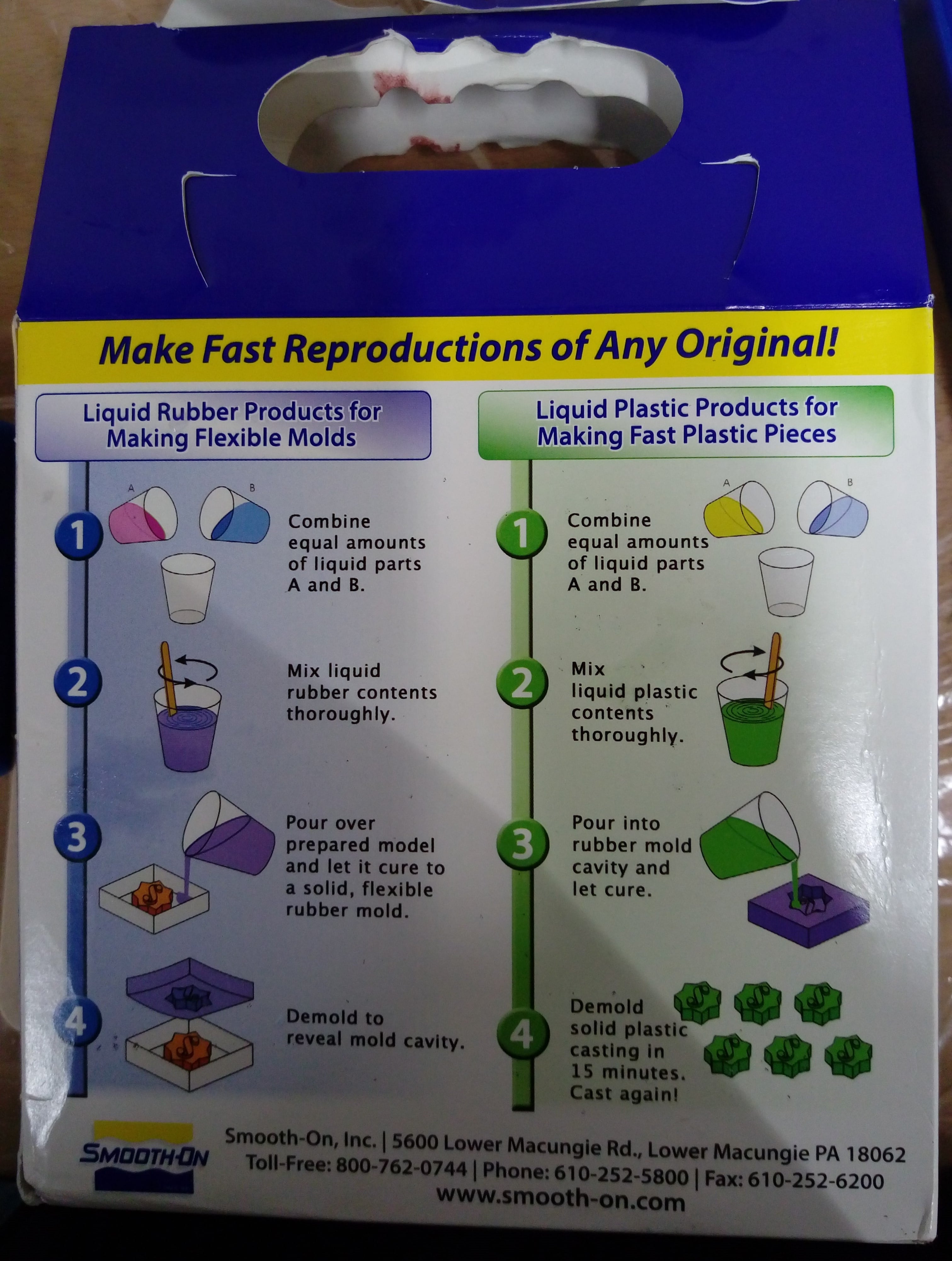
Also there are some general brief instruction on the case as shown below. I used this material to make a flexible molds. For more details I read the instructions and features of the material from HERE
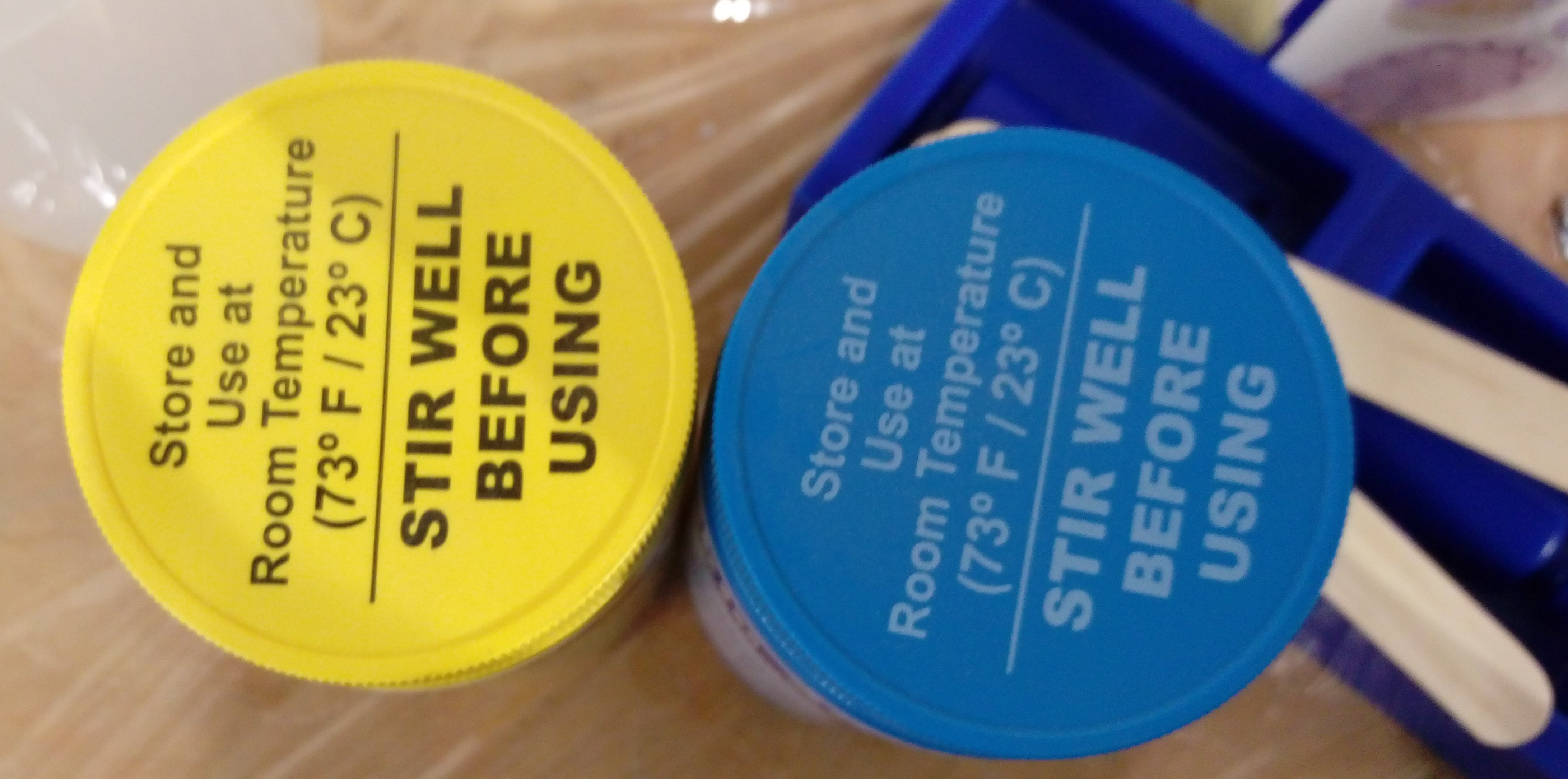
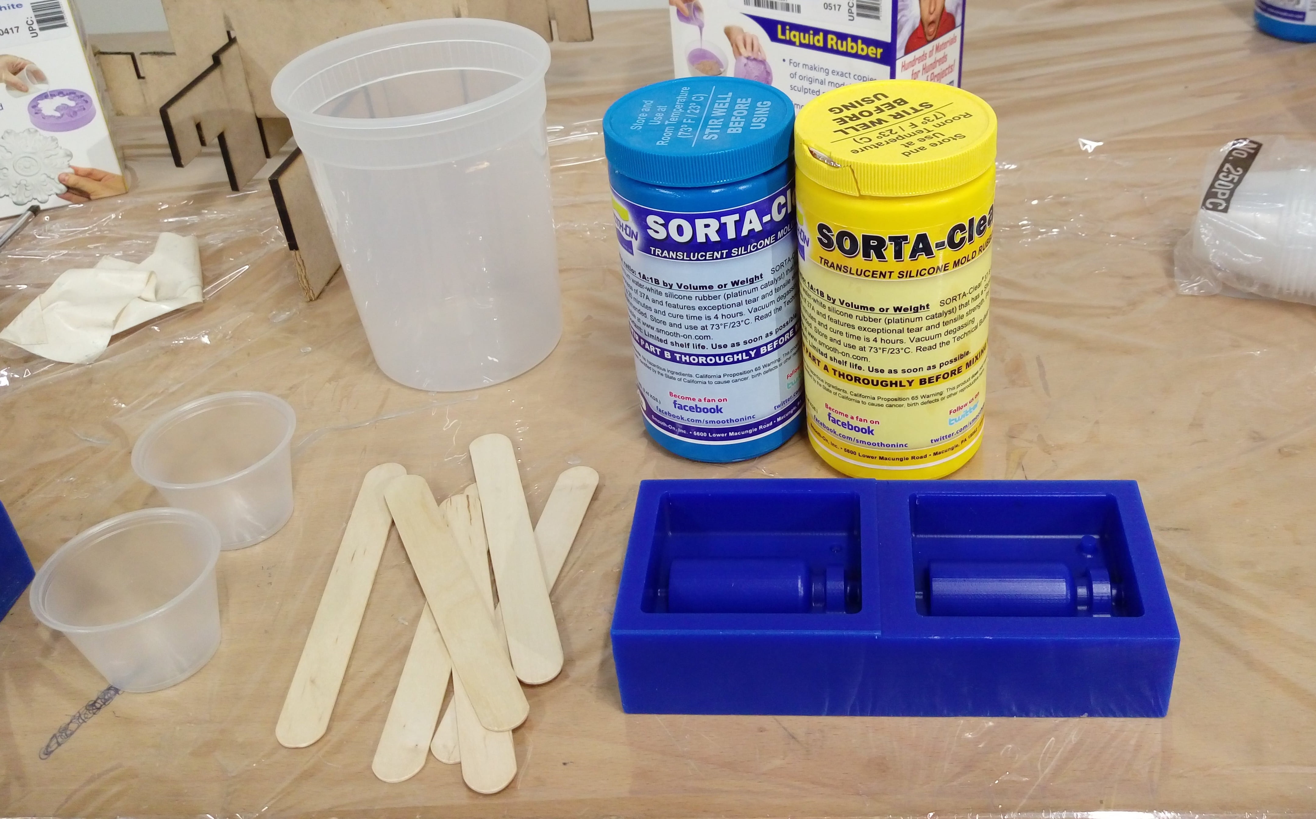
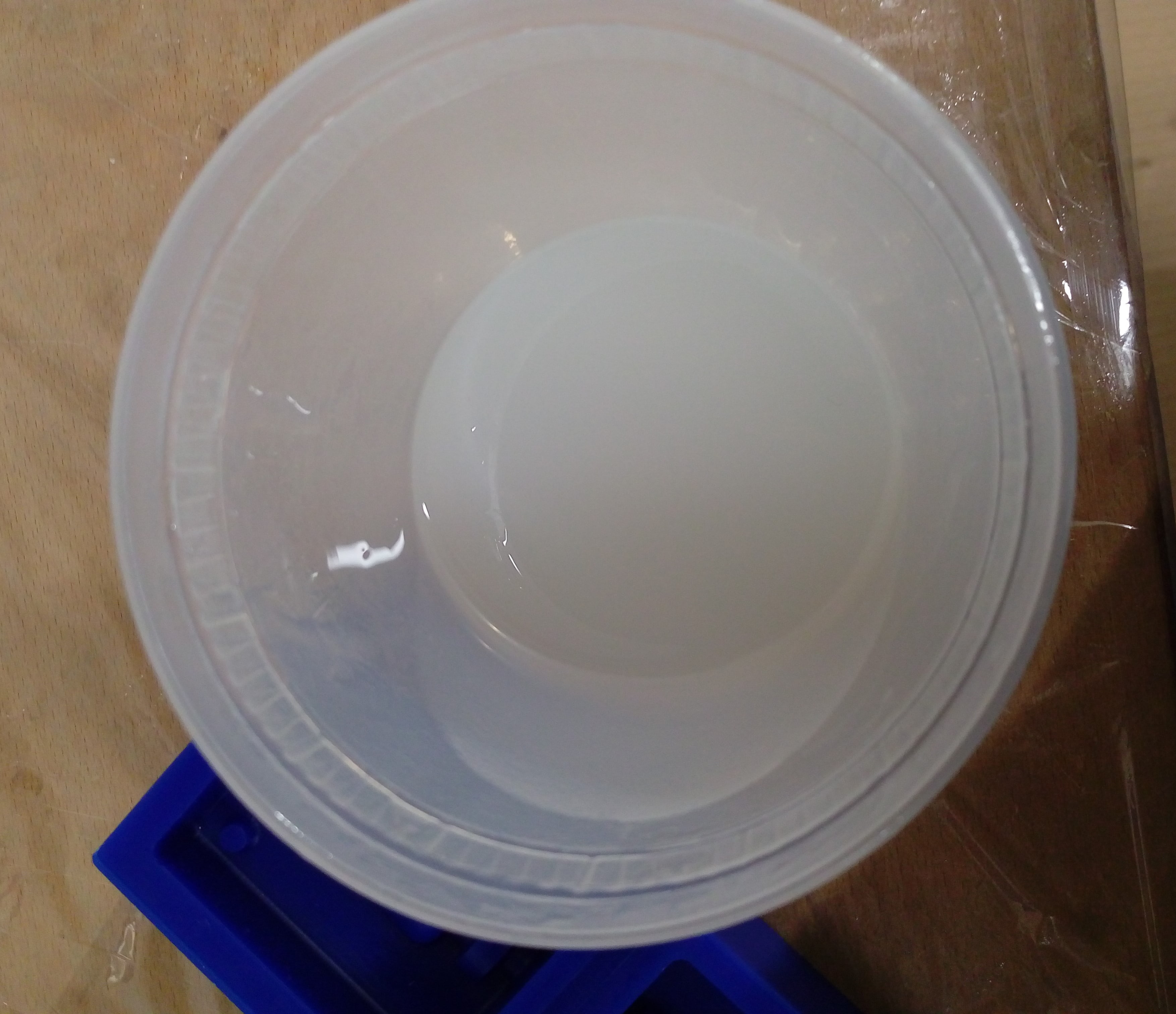
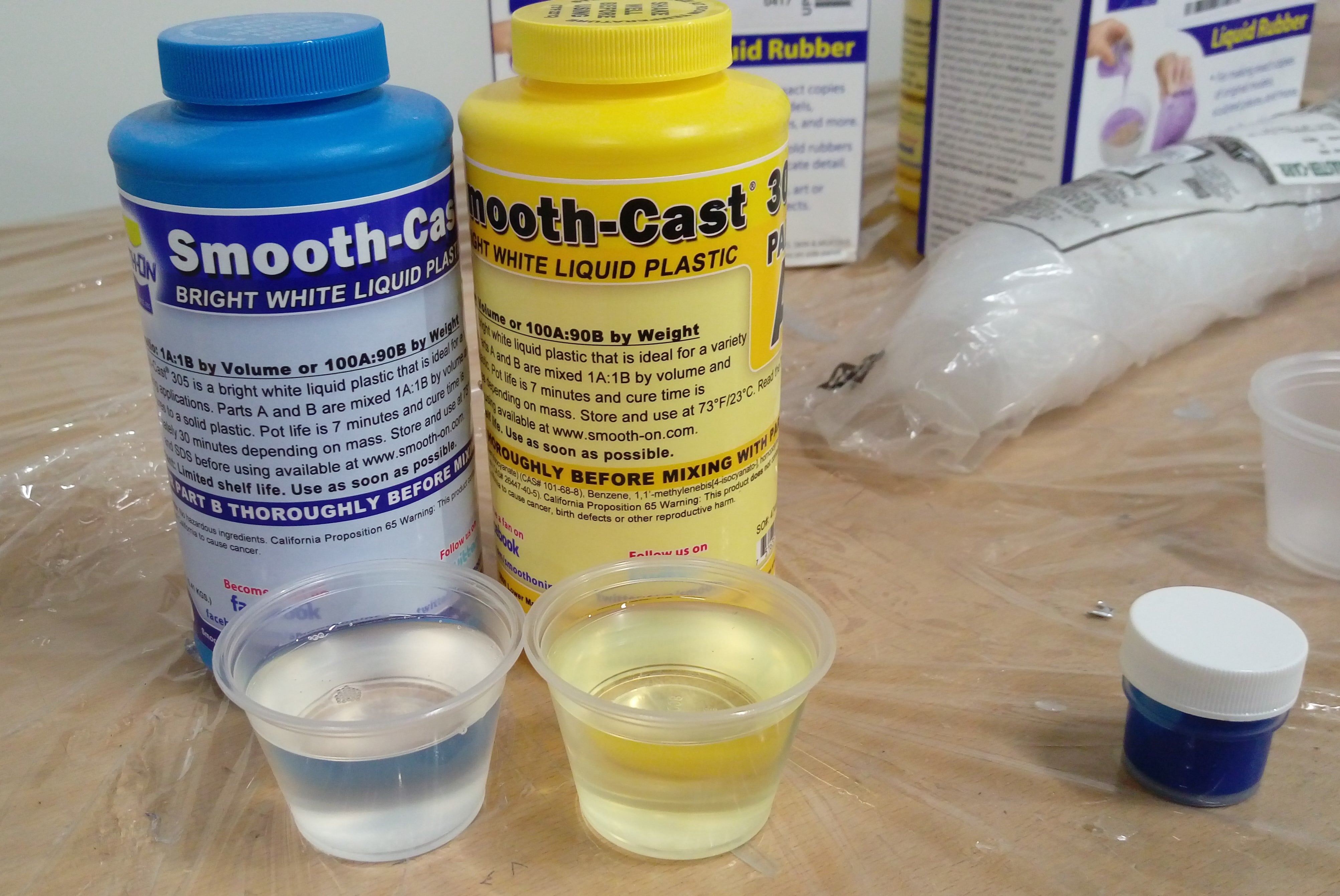
Prepare a container, small cans and some sticks to mix A and B parts with 1:1 ratio
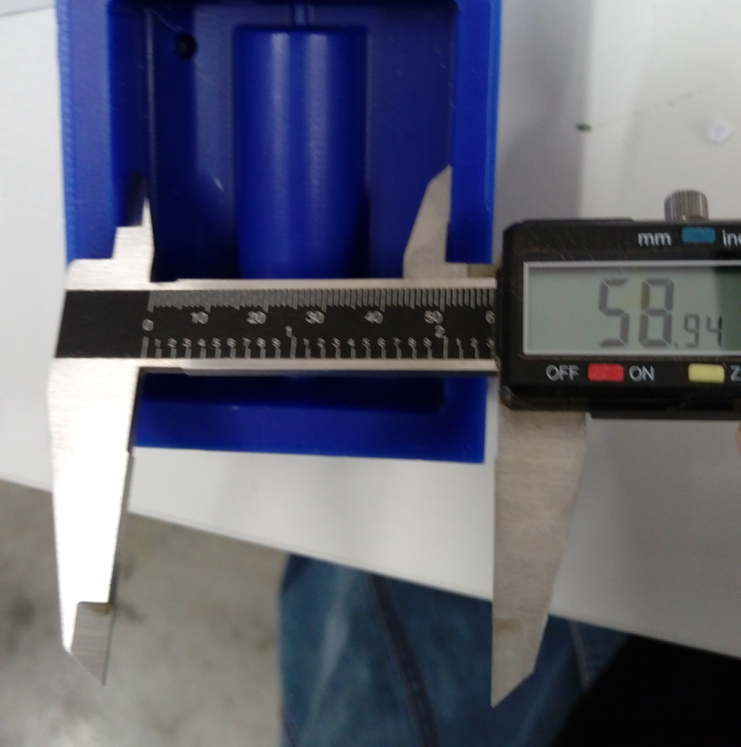
To approximately calculate the needed volume of A and B, I tried to calculate the volume of an empty mold by measure the dimensions as shown below. The wanted volume was 20.24x72x58.94= 86 cm^3
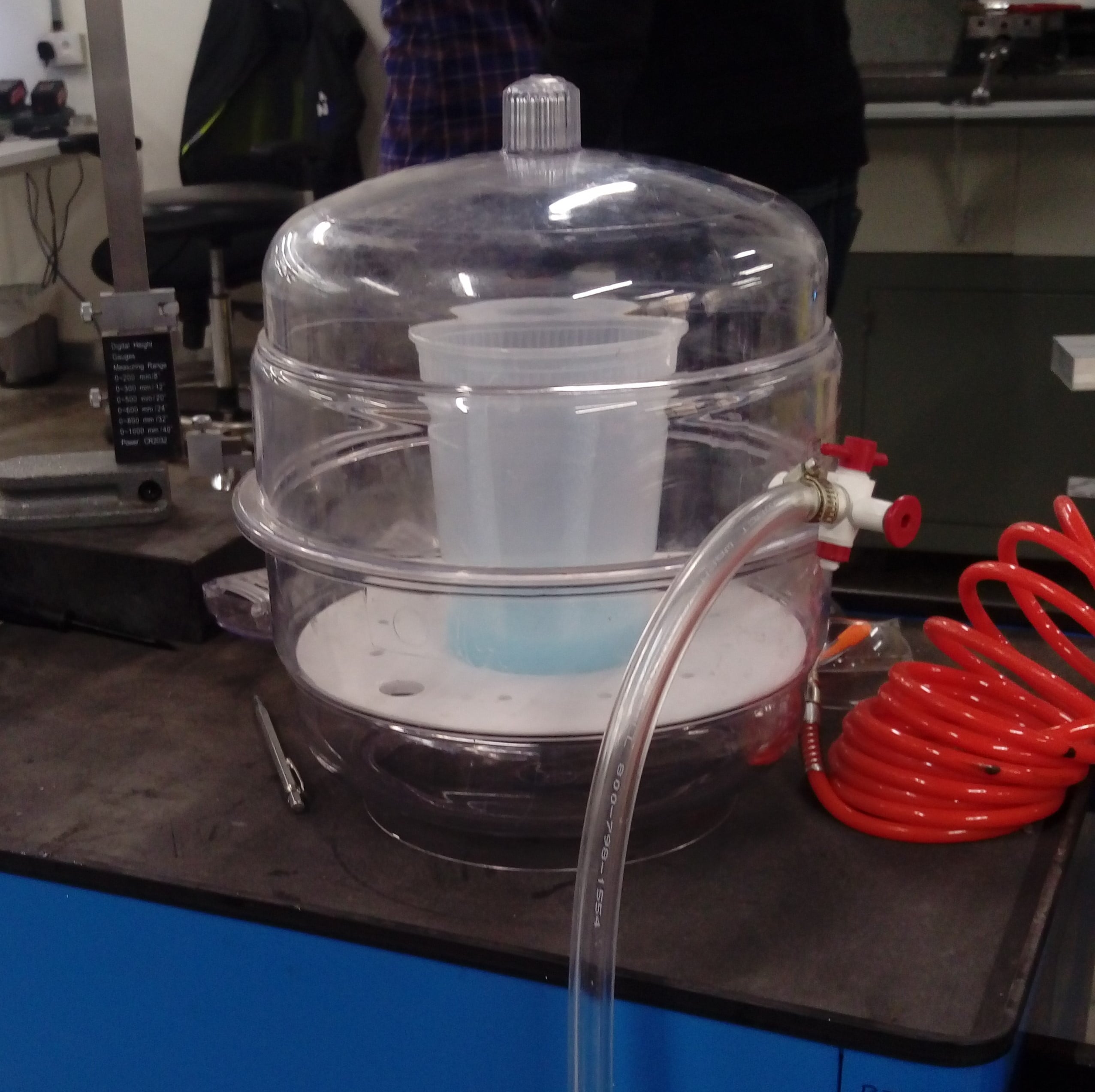
After adding materials I mixed them very will the but them in a vaccum simple machine to degas the mixture and remove bubbels from it.
Watch degassing operation
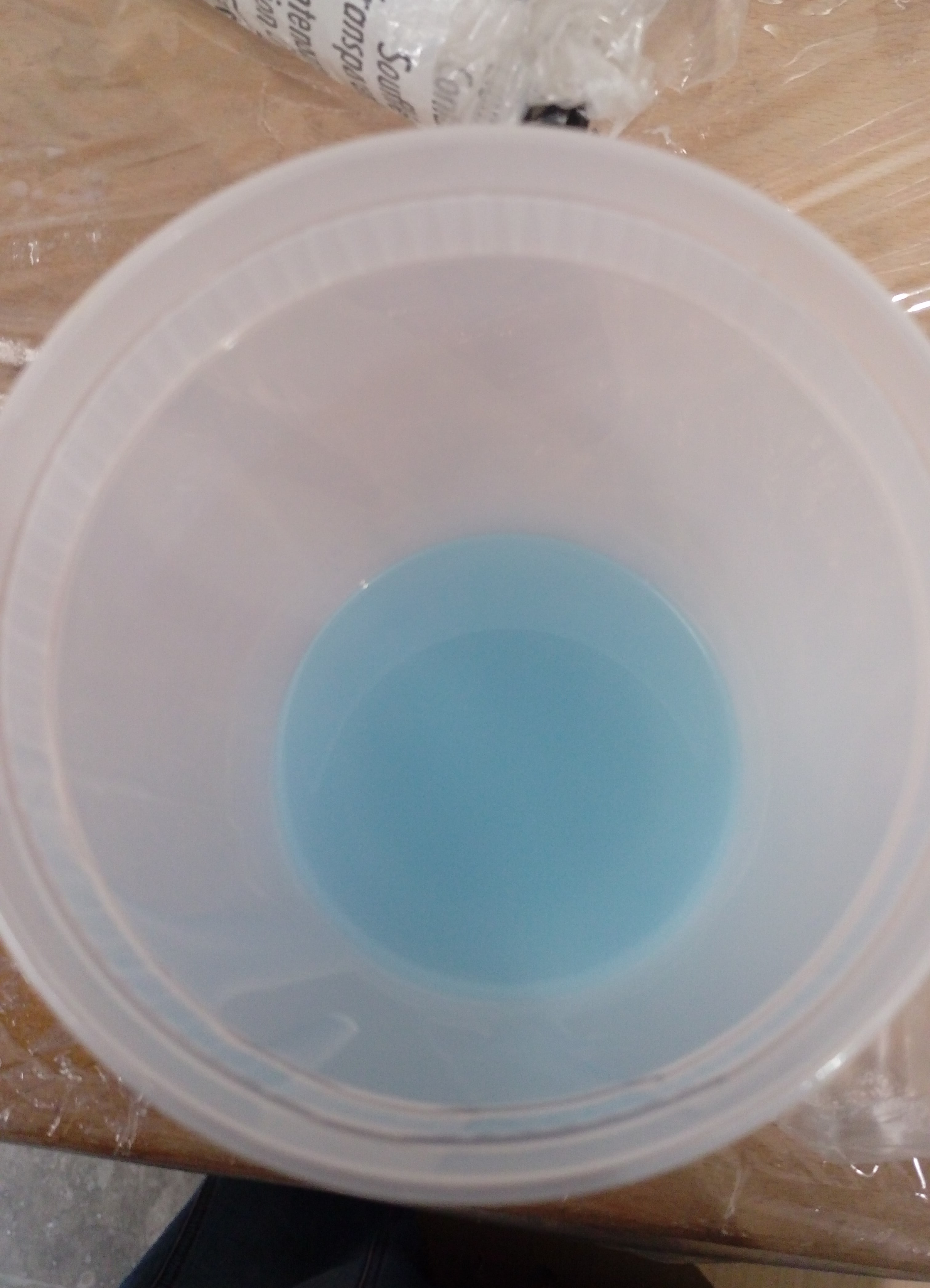
Free bubble mixture:
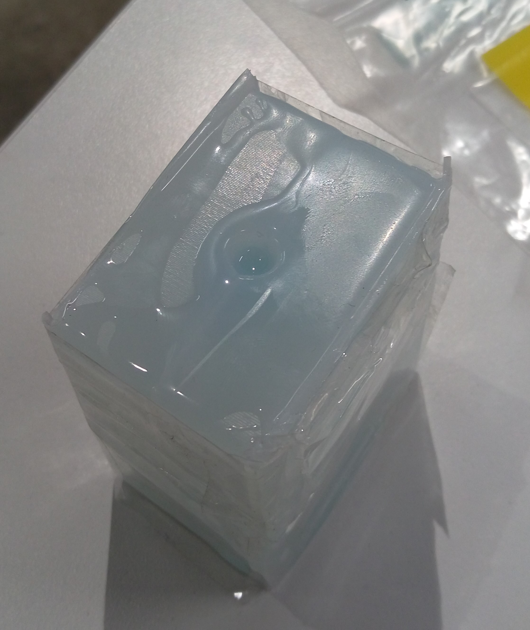
Then I slowlly poured the mixture into the mold starts from the middel of each side.
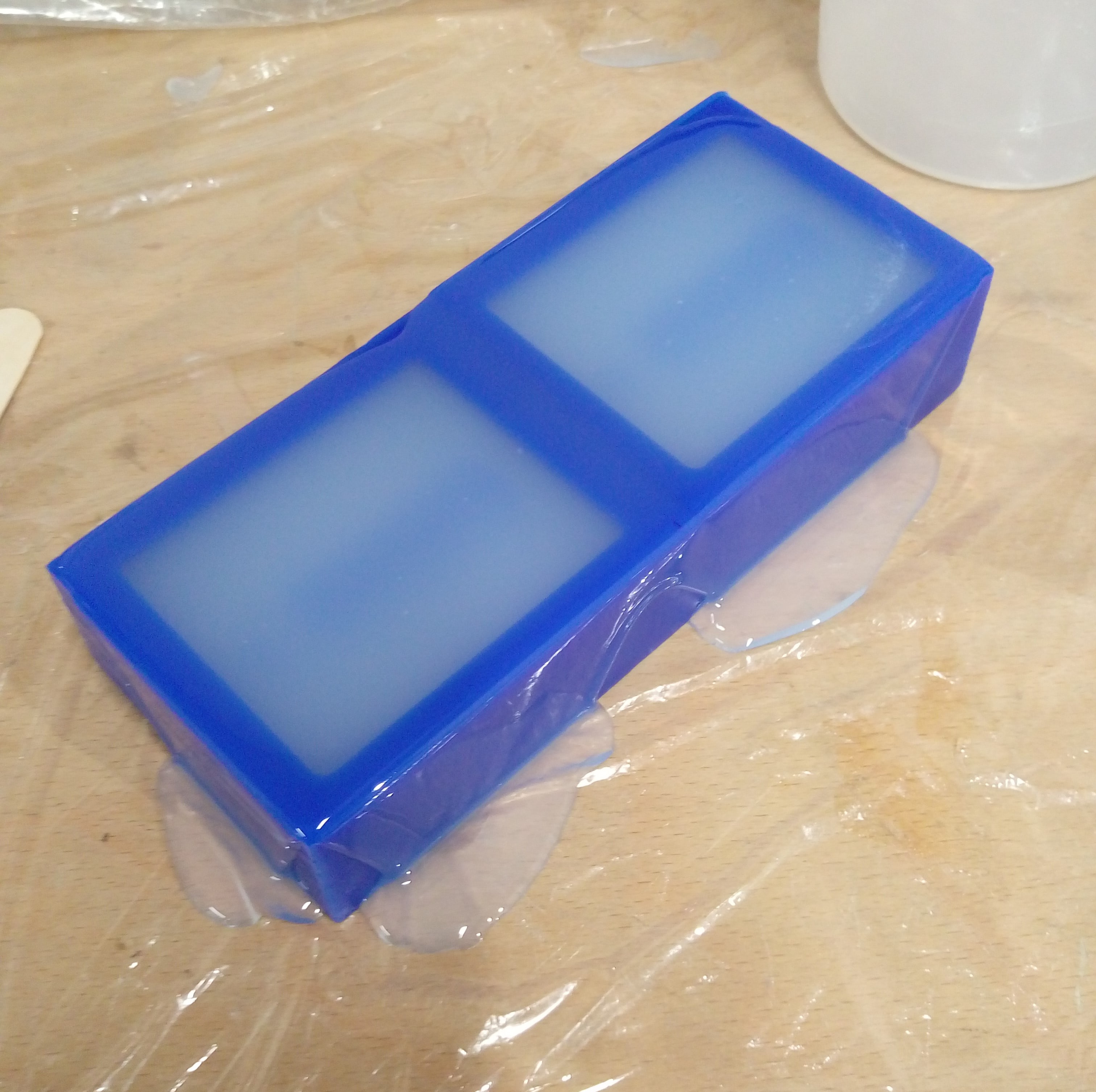
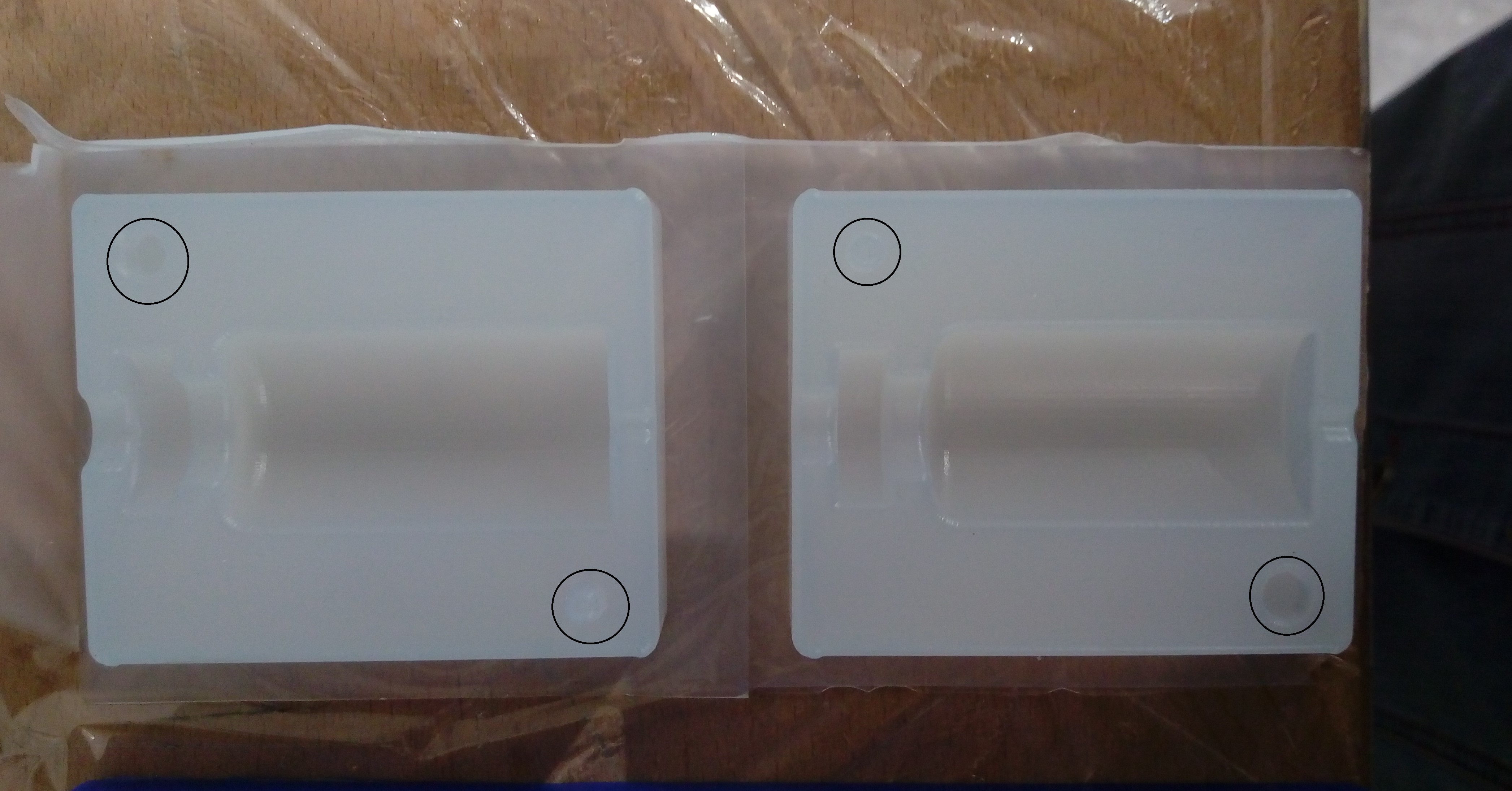
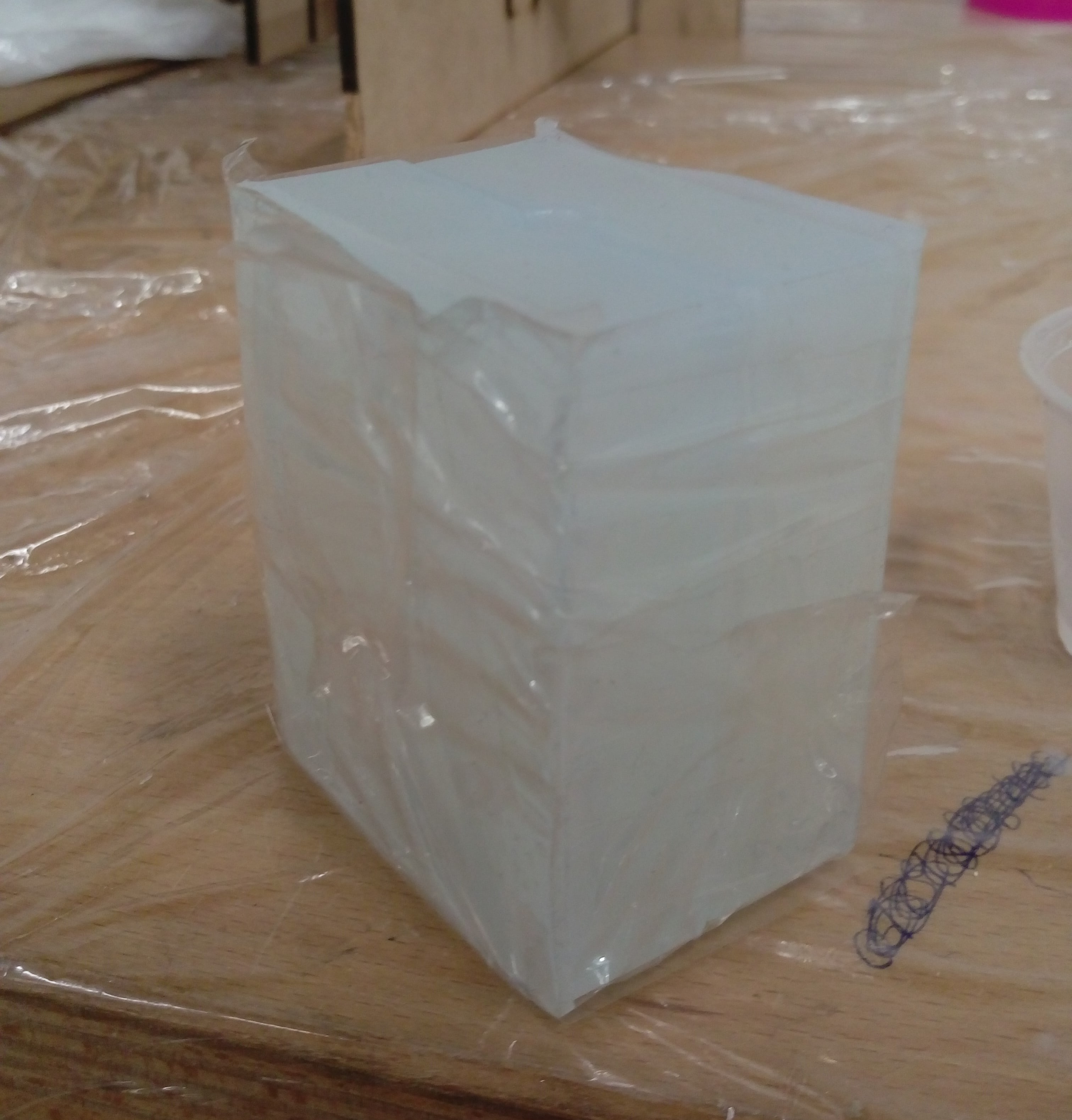
As mintioned in the datasheet the cure time for this material Dragon skin 30 is 16 houre, so I left it for the next day to dry completely. In the next day I came and remove it from the wax box. This how my final silicon mold looks like: it is very perfect !
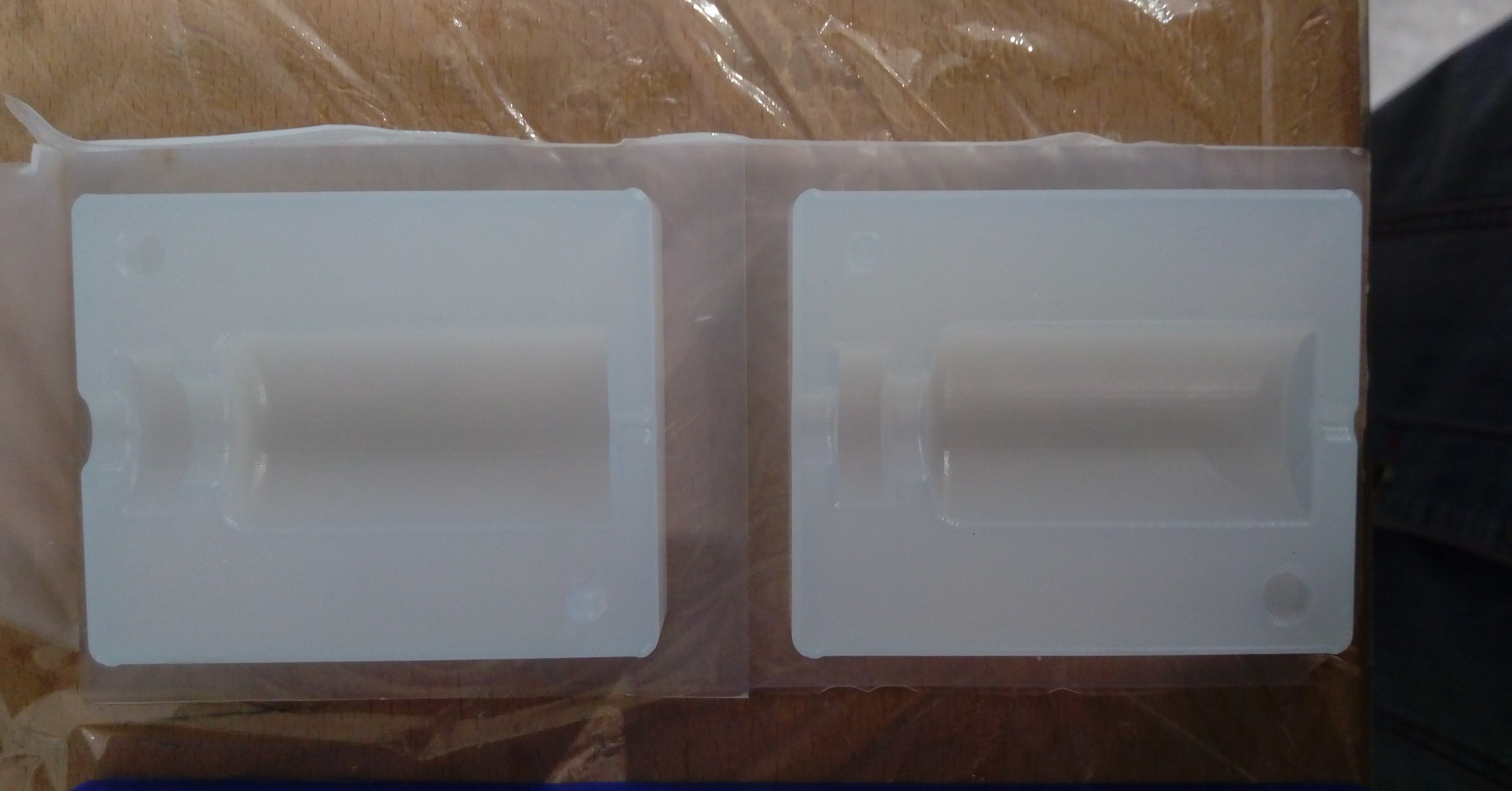
After I separated the two molds and tried to connect them to have a compelet 3D mold, I noticed that I made a fatal error!. I designed the pins and holes in the wrong places so I can't connect two molds correctly!!! I felt so bad and I wanted to cry and throw away my molds. :(
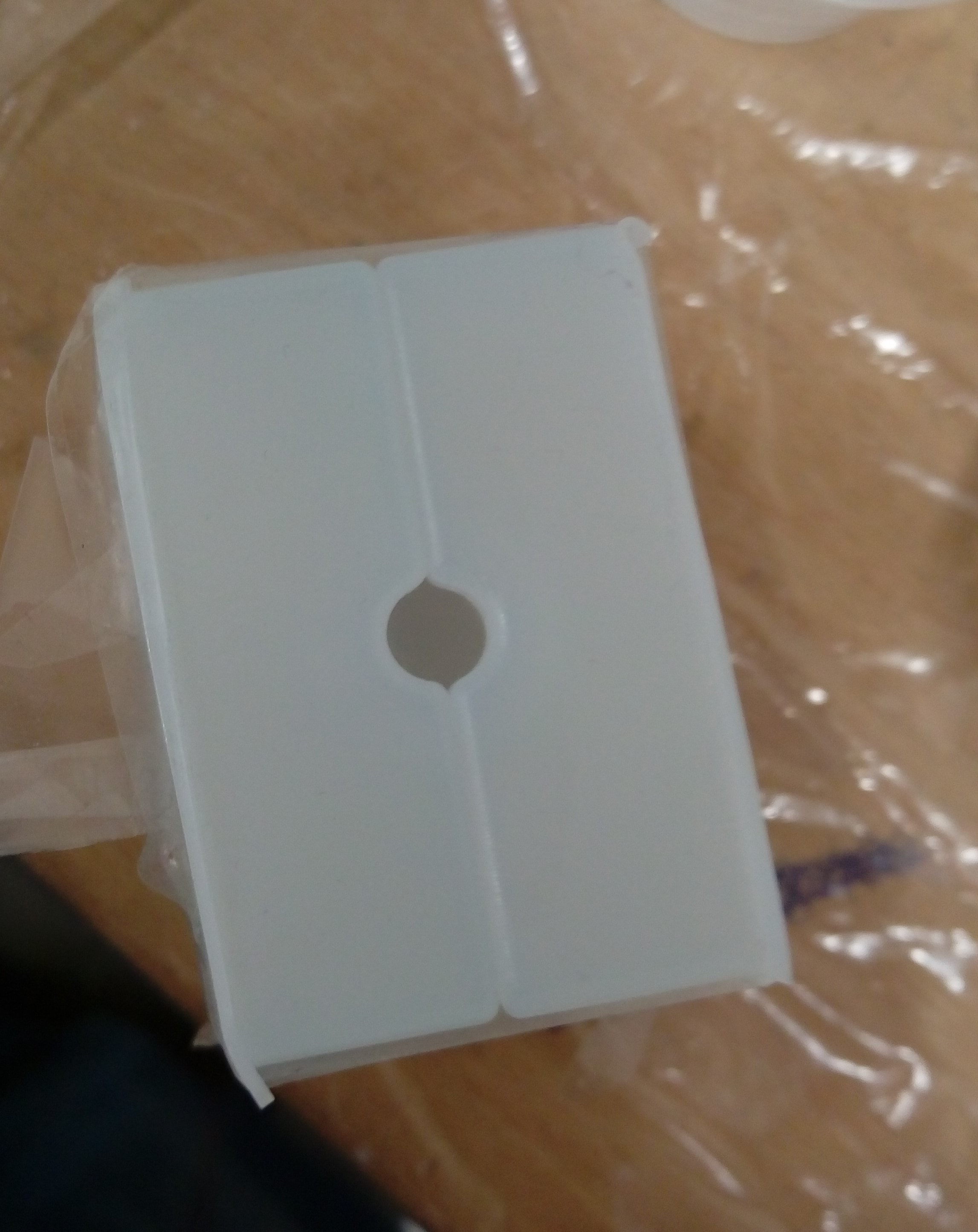
Fortunately I had an idea to fix this problem temporarily just I cut out the pins and used an adhesive tape to fixed them togother ( as shown in the figur below ). For a permenant solution of the wax box mold I will manually drill two holes at the correct pins places.
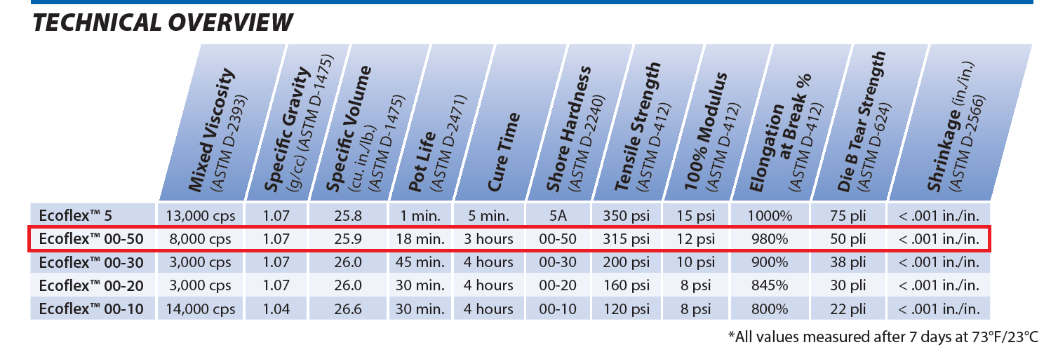
At this stage I had my silicone mold ready to pour any material in it. I looked for all we have in the lab store, but discouragingly I just found more flexible materials which called Ecoflex™ 00-50. The figure below has some main properties of it, also you could see more details from HERE
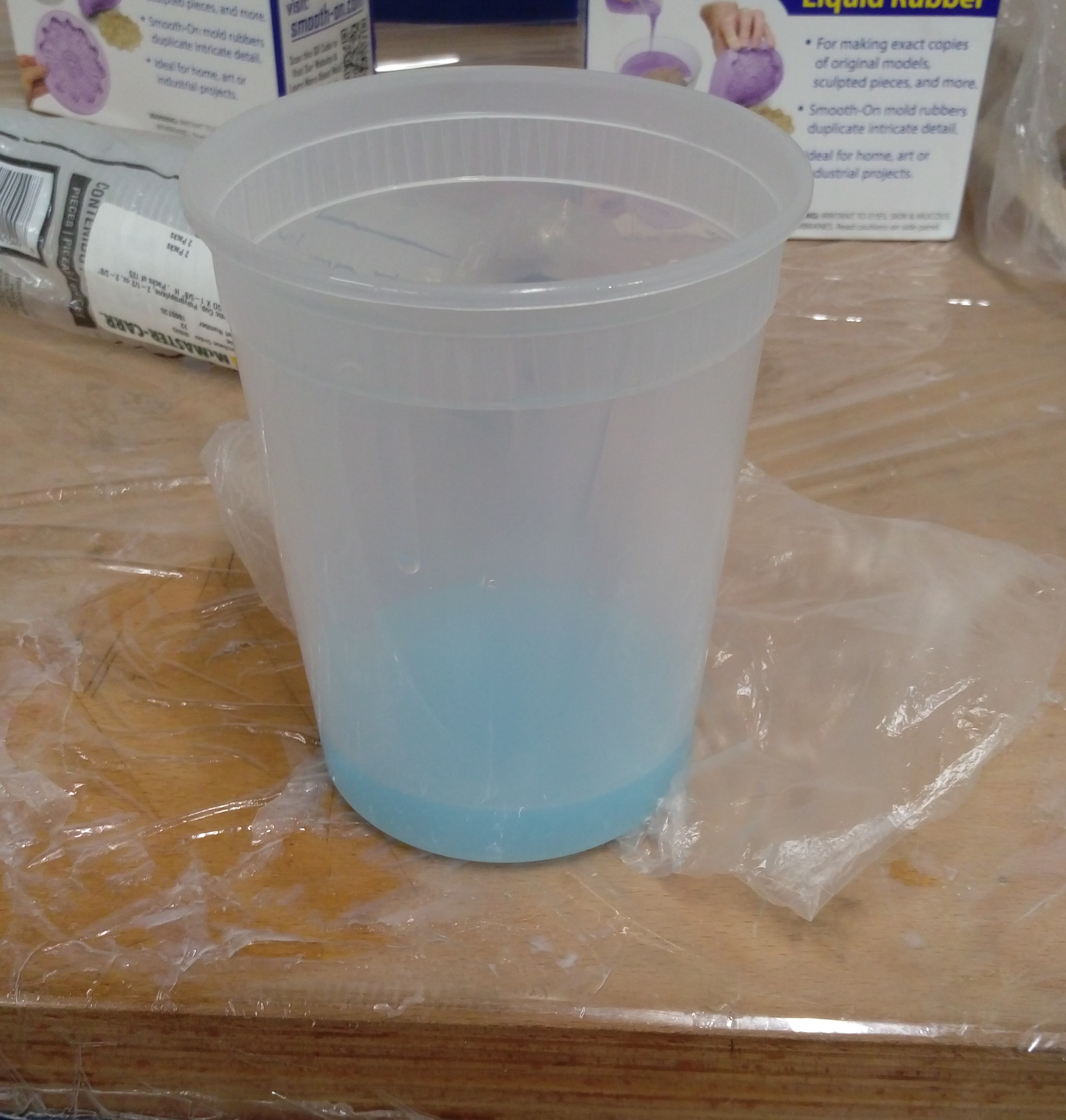
In this step I repeated what I made in previous step but I added some blue color to the mixture :). I mixed materials A and B with ratio 1:1 by volume. Then I degas it. After that, I slowly added the mixture into the mold. The following figures summarize procedure.
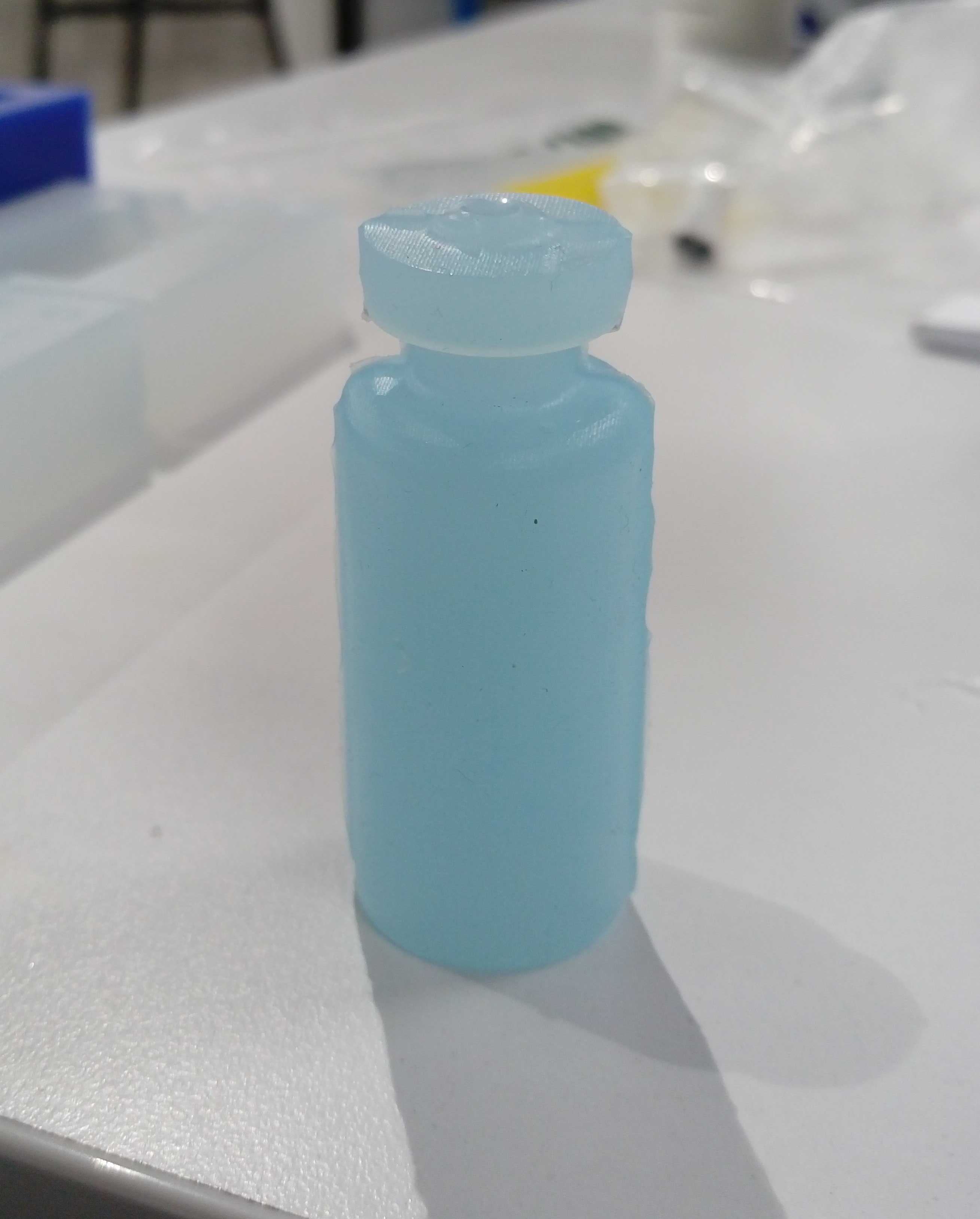
The cure time for Ecoflex is 4 hours. I waited for 5 houres, then took out the object from the sillecon mold. Then removed extra materials. Finally, my flexible vial looks like:
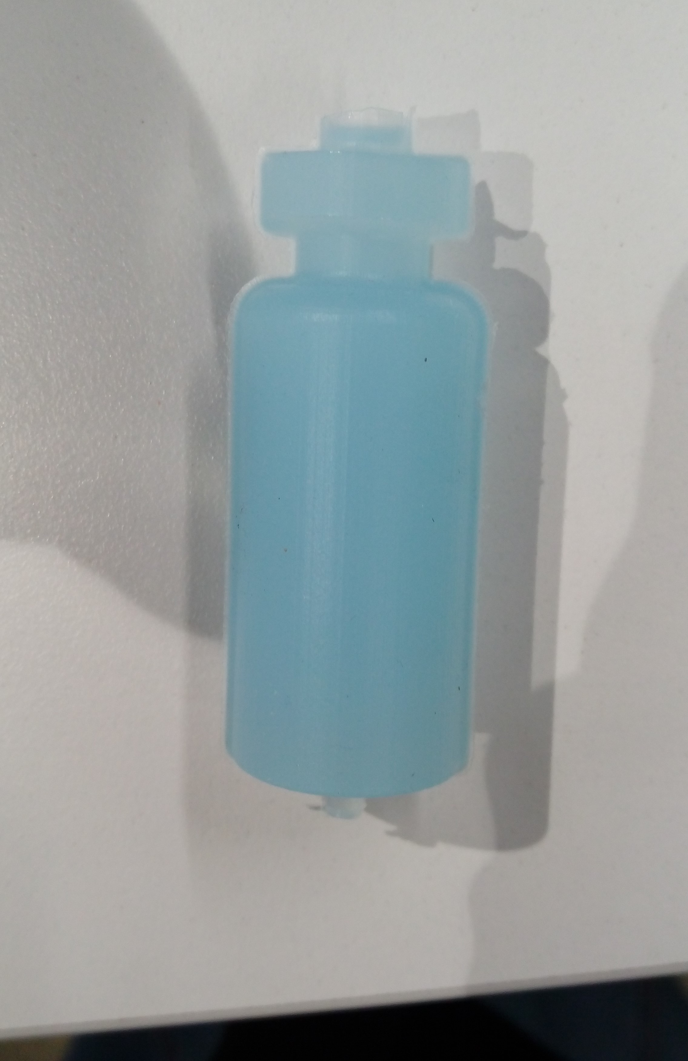
Then I removed extra materials. Finally, my flexible vial looks like:
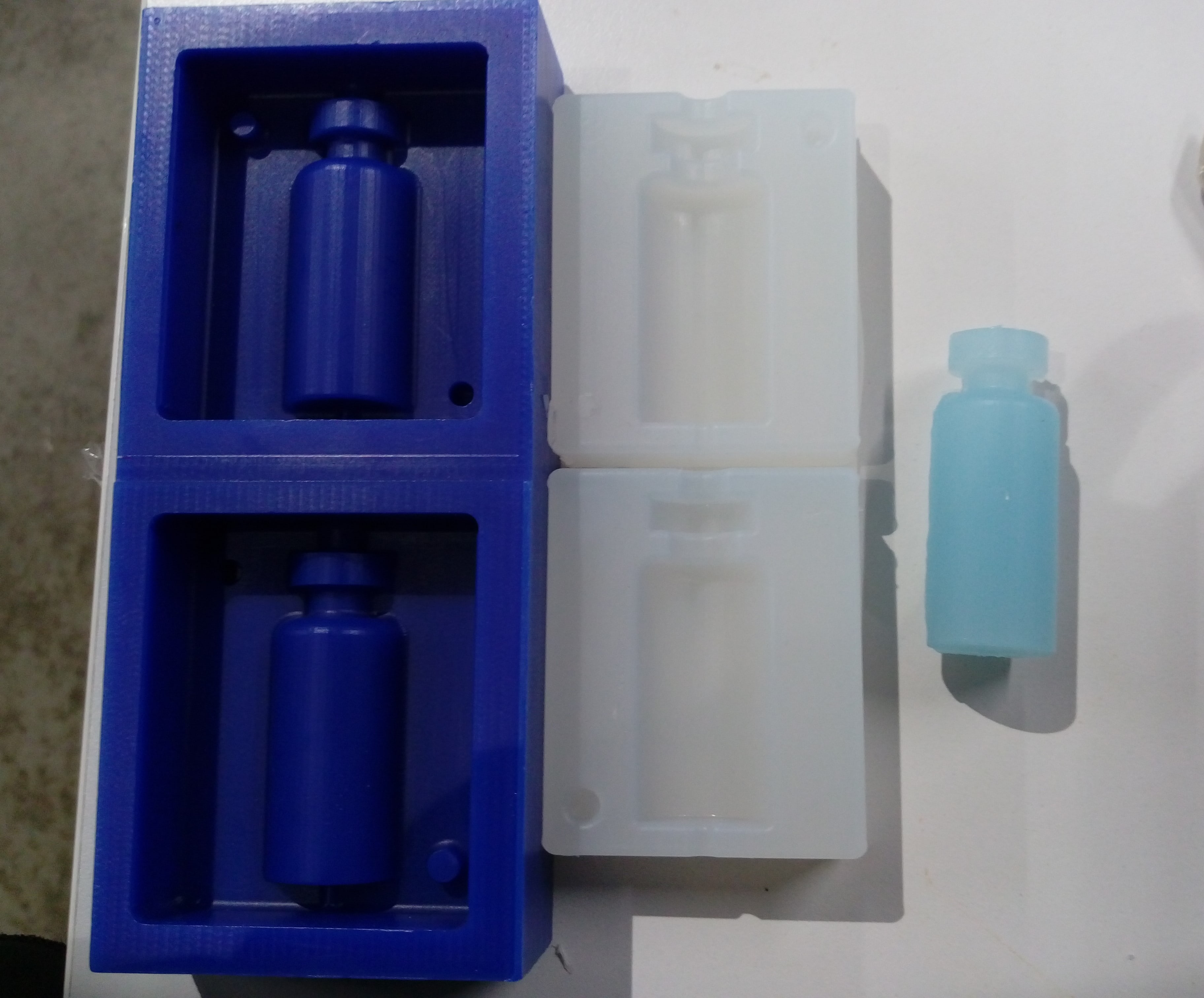
At the end this picture summarizes all steps in this week :)
To download CAD design: