

In this week we discussed a different CAD software types and several examples for each type. We asked to choose at least three new software. Because I'm familiar with parametric CAD software in general, such as SOLIDWORKS, CATIA and Fusion 360, I decided to start work with a vector CAD software then try another softwares.
The softwares that I would document my works in, are:
Start with Inkscape which is a free light vector graphics software.I tried to draw a base for my final project robot It was a really tough task, I recognized that it is much harder than any parametric software and it takes much more time. But finally I'm happy to learn a totally new drawing method.
First step is to download the software form this link Then I created a new from templet file whit A3 vertical page setup also I added grids to my page to easy the drawing. The result was:
I draw a rectangle its icon from the left bar, then added fillets on corners by drag the small cicle which appears at the top right corner of the drawn rectangle
Then I added an ellipse by selecting its icons from the left bar
Next I joined the two shapes to become one shape using Union command from Path list after selecting both of them:
To make a hole in the center to let the cutting tool moves up and down and slots for wheels I draw the red circle and rectangles then selected all the element and used Difference command as shown:
The final result was shown below. Although it is so simple shape, but it takes several hours from me to draw it successfully'
After that I saved the file with ".dxf" extension, then I open it by SOLIDWORKS using these settings:
The opened sketch looks likes:
Next step, I extruded 2D sketch to make 3D object as shown:
The final result was
To download my files:
The next software was blender. It was a really horrible experience I tried hardly to draw a very simple wheel, but the result was awful. Anyway, it was my first time using 3D graphic software and it seems it will be the last'
The start screen of blender
I started by drawing a cylinder without thickness
Adding thickness to the cylinder
Make the cyliner smooth
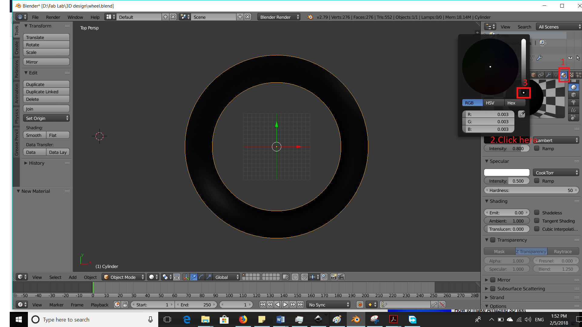
Change the color of the cylinder to black this part is the outer plastic part of the wheel

Next Add small cylinder in the middle of the big one
Next Add small cube in the middle of the cylinder
Then make a hole in the cylinder by these steps
The result shape:
Then to cover the gap I added other cylinder between them
Finally change colors
Download File:
After the previous hard tasks I decided to back to my parametrice easy world, so I started with a totally new software for me Onshape
it's an online software so by visiting their website and create a new account as a FabAcademy student I could start PLAY again'
I tried to draw a plastic wheel like this one:

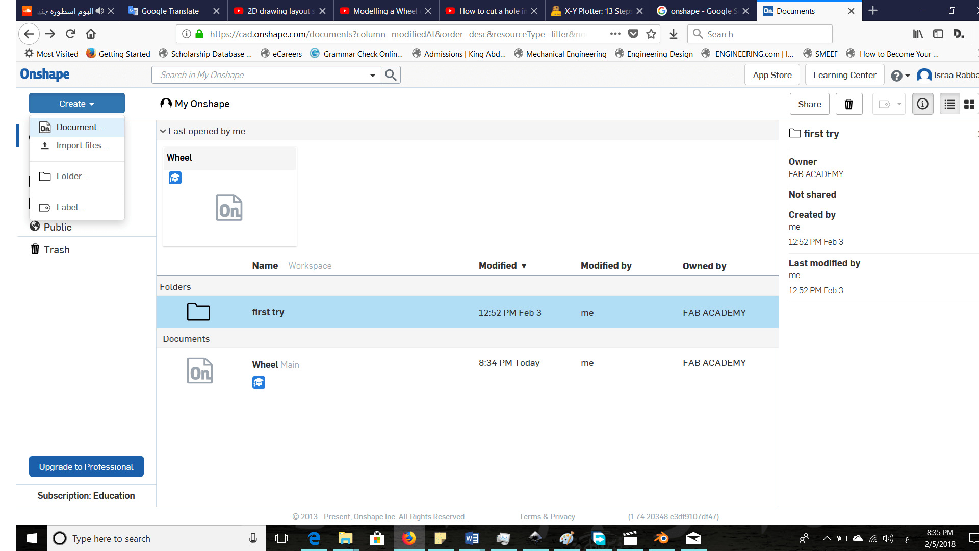
I entered my account and added a new document

Change default units to millimeters
Add sketch on top plane
Start with a rough sketch
Add dimensions and constrains to the sketch to become fully defined
Exit sketch and Revolve it as shown
Add a new sketch also on the top plane to draw the middle part and choose its dimensions
The revolve the second sketch
Add a new sketch on the front plane using a circular pattern icon
Extrude sketch as shown:
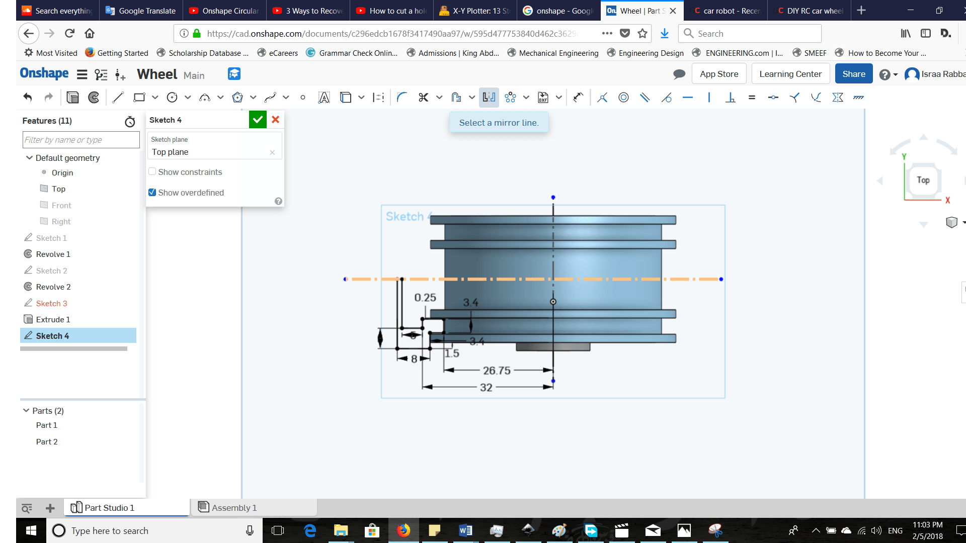
To add the outer rubber part of the wheel. First, I draw this sketch
Mirror previous sketch:

Result after revolve:
Finally, add different radius fillets
The final wheel looked like:
Download File:
The power of the onshape as any parametric software is when I change one dimension in a sketch hole part will change automatically as I did in this example: