Hello World

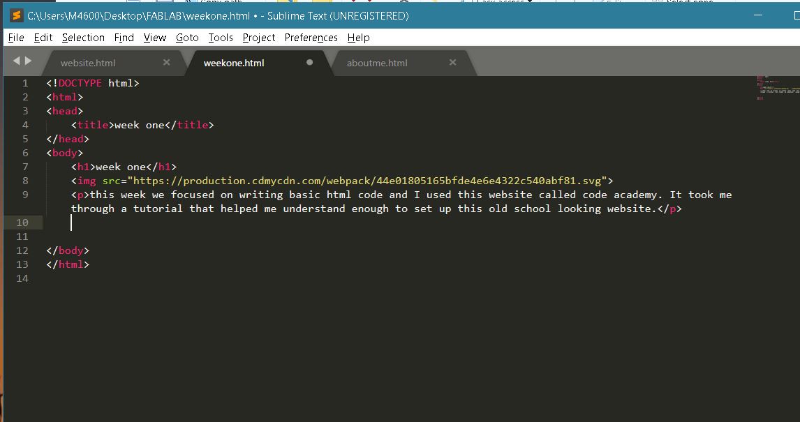
Another helpful tool is the Sublime text editor. It helpfully color codes elements of the html code to let you know you're doing it right and even autocomplets some elements of code.
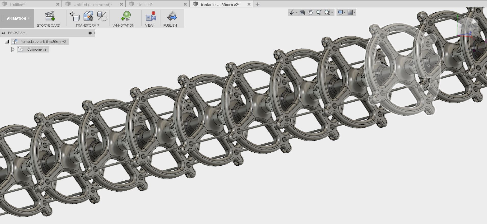
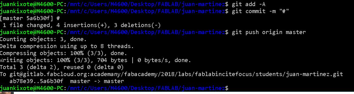
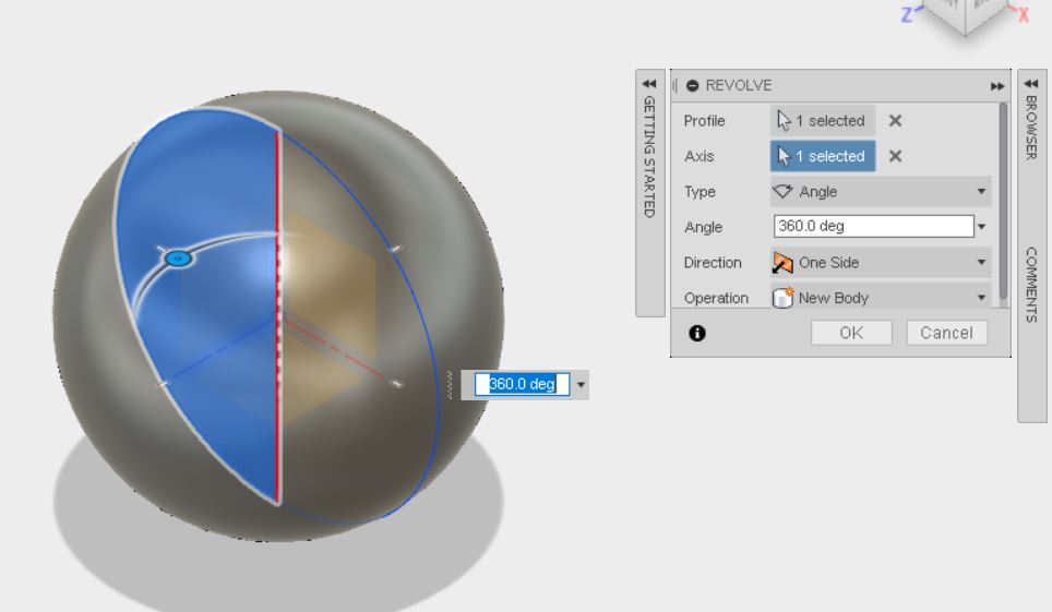
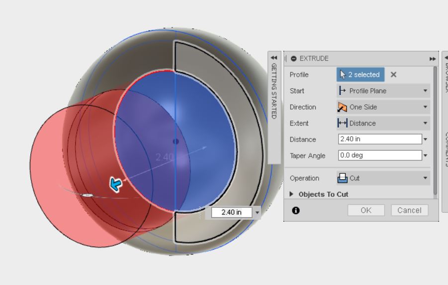
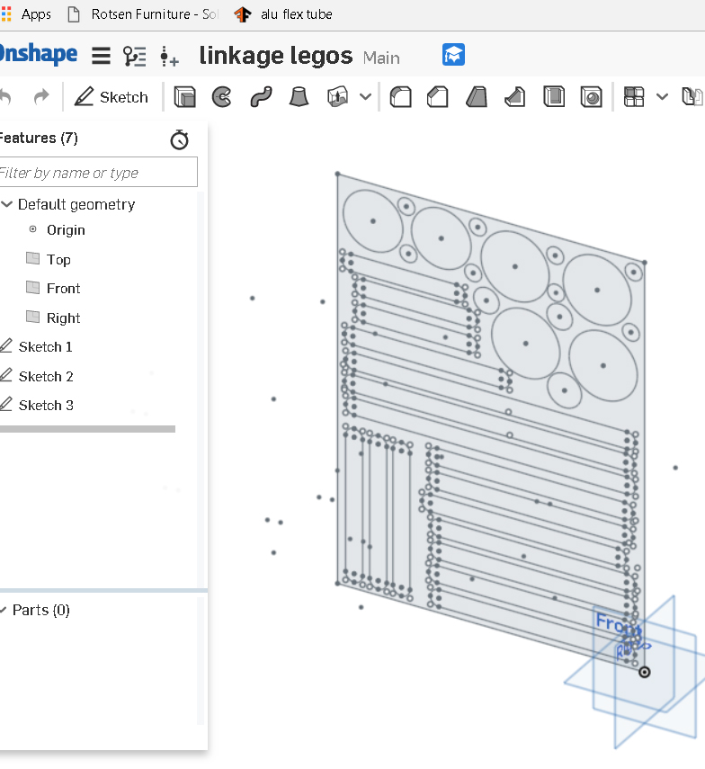
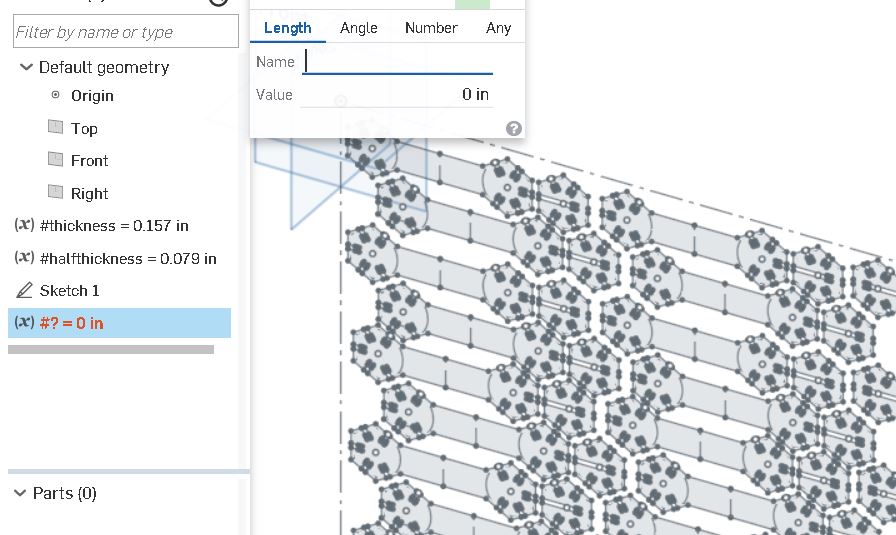
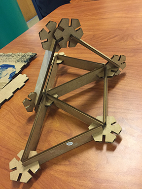
these are the steps necessary to push new info onto github I'm developing a tool to model the linkages in my kinetic sculptures with cardboard. I'm calling them "linkage logs". I do childcare at a school in my neighborbood every Wednesday and I'm gonna bring linkage logs so I can model linkages with my kids! once I put motors on them then we can make cardboard robots together! the image below links to the dxf of my linkage logs I'm trying a bunch of different modelling programs to try and find the right fit. So far I've tried Fusion360, Solidworks, and Onshape. I'm pretty familiar with inventor so I'm most comfortable using Fusion360 but I've also been trying to get good at Onshape because it's so awesome that it's free and open source! click the picture below for the stl file of my tentacle ball joint mechanism to make this tentacle unit I made a circle and revolved it into a sphere to make the female part of the ball joint i made a slightly bigger circle and then extruded a cut through it where the male part of the ball joint cuts through this week I set out to design and cut a simple building block system that slots together.I learned about parametric design and I tried designing in onshape, fusion, and solidworks. I started assembling in fusion and noticed that my system the way it was originally designed wasn't working. I couldn't use it to build in 3D so I redesigned it with links peices and strut pieces. here's a screen shot:
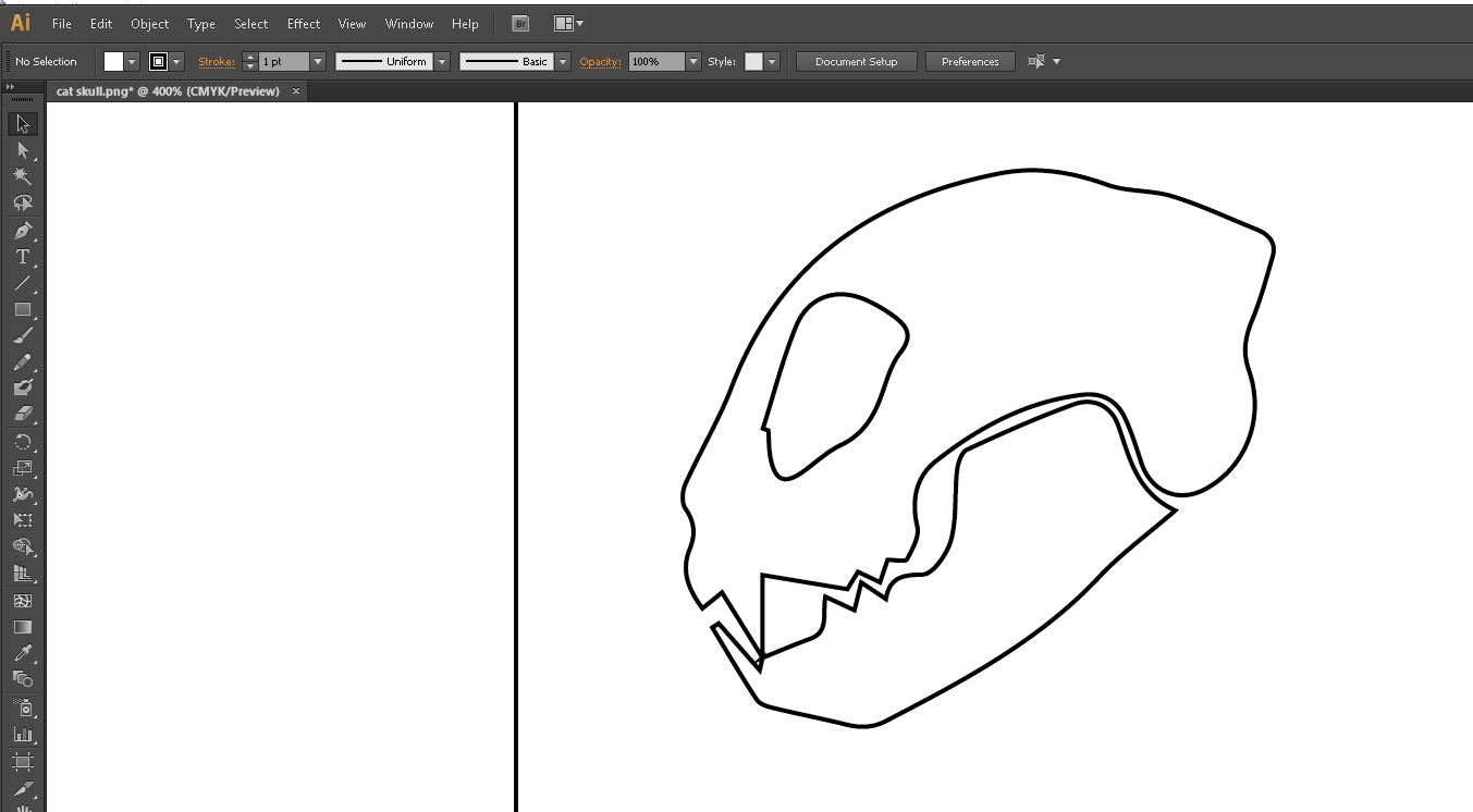
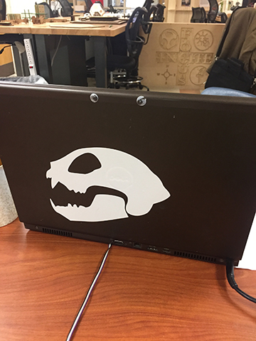
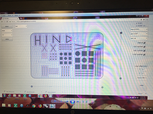
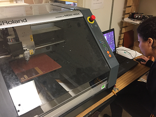
in order to make the design parametric I made a variable called "thickness" that changes the size of the slots depending on the thickness of the material I used inkscape to turn my png into a pdf and I learned that, at least on our setup, the line width needs to bee .001 of an inch to cut lines as a vector here's a link to my press fit kit in onshape next i did a vinyl cut sticker for my laptop. I found a simple catskull vector online then i brought it into adobe illustrator and expanded it, removed the fill, and added a stroke then i took it to then vinyl cutter and cut it out. it's almost as easy as using a printer! This week we made pcb boards cut with the our little cnc mill. I used Jonathan Ward's shield maker app which looks like this
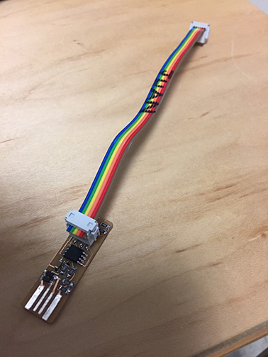
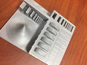
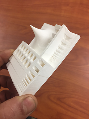
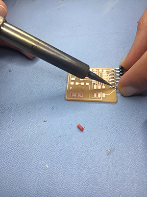
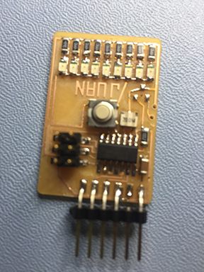
This app makes it really easy to design and alter boards and I love that it's simple enough that you can use it on a smart phone. It does hide a lot of the plumbing under the hood. For example the feed rate is automatically generated. It generates g code automatically and communicates beautifully with the cnc mill Here's how the boards turned out. These two were test boards to see how accurate our milling machine is which was this week's group assignment I found the surface mount soldering to be really easy. I've done a bit of through board soldering but this was even easier in my opinion. Maybe because there's less copper to heat up in this case. Here's the finished board with all it's components attached
week two: computer aided design

week three: computer controlled cutting

week four: electronics production
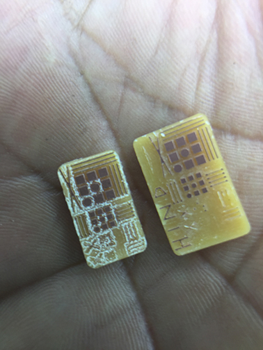
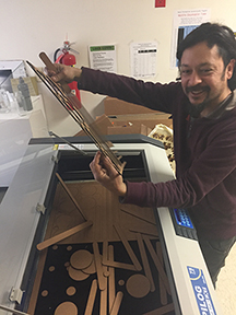
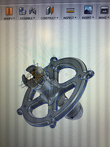
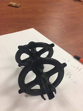
This week I worked on designing ball joints that would pop one into the next to make a tentacle that could be actuated by cables. Ball joints cannot be made subractively because it's a positive sphere that fits into a negative sphere and a negative sphere requires an undercut that would be diffictult or impossible to do subtractively. I mostly worked in fusion360 and made several iterations of it with various 3d printers. Some were more successful than others. below are some of my attempts:
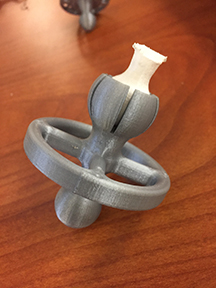
this one worked great except I wanted it to have a ring around it to attach rubber bands and have cables run thru the length of the tentacle.
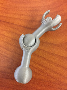
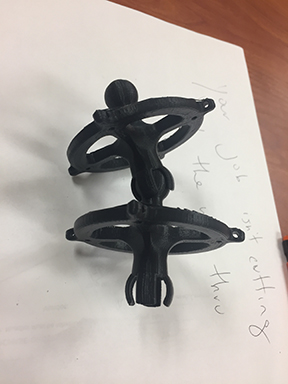
with these next ones the socket kept on breaking. In my attempts to make it stronger i made the socket thicker but it reduced it's flexibility and they kept on breaking when i would attempt to pop them together.
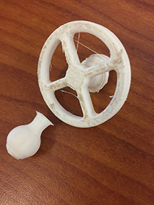
this one was pretty good but the parts that formed the socket were still too thick. I also tried making the ball .002 inches thicker but this made the socket too stiff to move
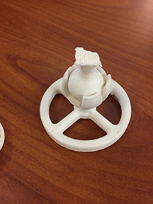
this one was starting to be closer to what i wanted. Some of these iterations were 50% smaller than what i designed to save material while i worked out the kinks in the design
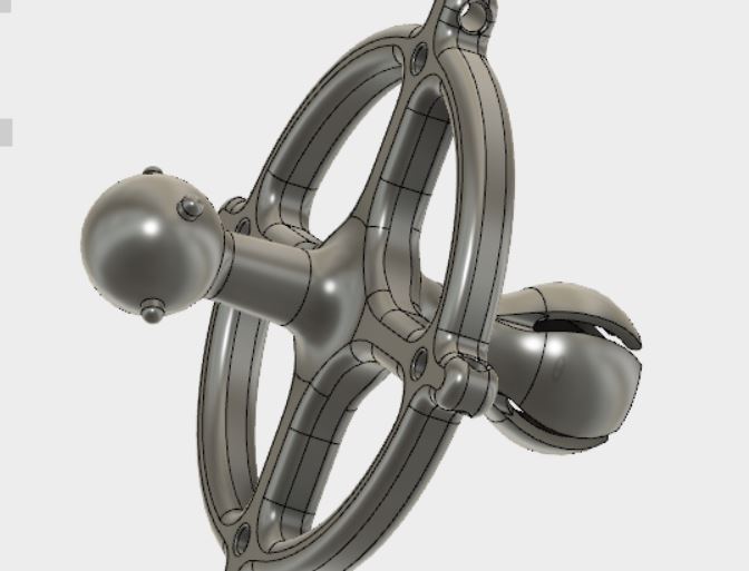
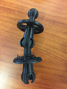
this is so fare the final iteration of my design in fusion360. I added some nubs on the outside of the ring to attach rubber bands so it can spring back to being straight after beeing actuated into a curve with it's internal cables.
 I got some plasticine so I could make a tentacle and scan it in 3D but the experience was very dissapointing. first I downloaded ReCap from autodesk and took several pictures of my tentacle model but when i went to upload them into the program i wasn't able to produce any of the file types that can be read by the program. here's a screenshot. If anyone out in fab academy world has any suggestions I'd love to hear them.
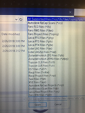
it seems like these are all weird proprietary file types that I'm not able to generate :( it's too bad cuz i was really excited to scan my plasticine model! If anyone in fabacademy world has any suggestions about that i'd love to hear about them!
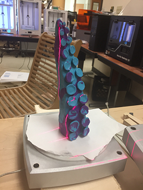
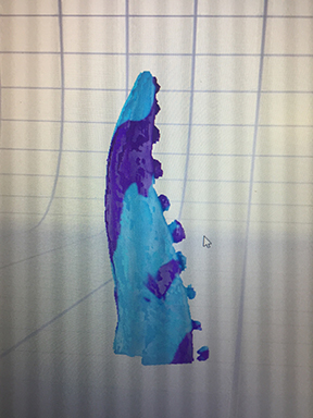
next i tried using the nextengine 3d scanner and after a lot of fussing around with the software and locating a bunch of serial numbers and passwords thanks to the great Blair Evans I was finally able to get it to work! here's my results:
here it is in fusion!

Here's the printer tests for the group project
 here's a link to an stl file of my tentacle scan
This week we focused on simple electronics design. The assigment was to add a switch and at least one LED to a board. I chose to add 9 LEDs in hopes that it might be bright enough to make a blinky light for bike safety
so i designed a board using Jonathan Ward's open source shield design software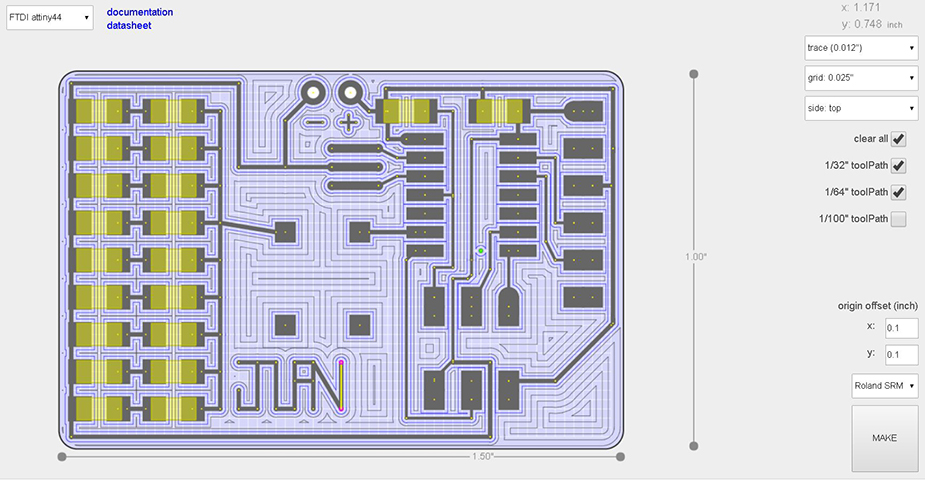
Then I soldered on the components
and it came out like this
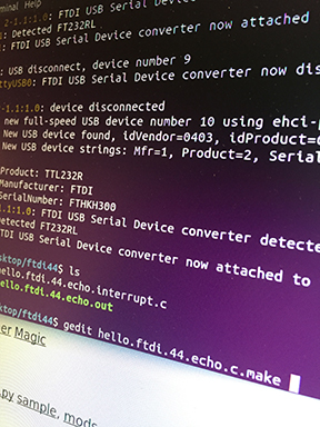
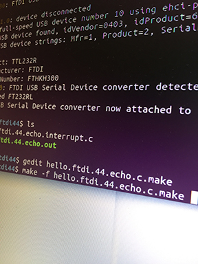
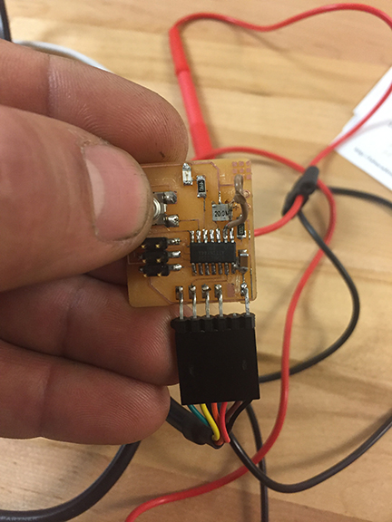
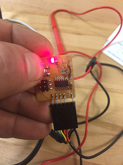
 then i hooked it up to my progammer board and flashed some programs onto it like this:
fortuneatly it worked perfectly the first time!
and I hooked it up to the ocsilloscope while it was running the echo program to measure what was happening
This week is really exciting! The assignment is "make something big". I've been designing some furniture ever since I started learning 3d design in the first week. The first project I got obsessed with is trying to nest a very sturdy desk design that would fit on a 1/2 sheet of plywood. Here's the design I came up with. I used onshape to design it.
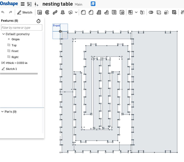
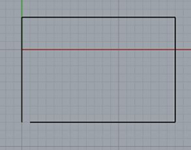
but then I had to bring it into rhino to clean up the drawing and by that I mean getting rid of lines that were doubled and loops that weren't closed like in the example below. every cut operation like a pocket or a profile had to be able to be selected w just one click on any of it's curves. So for example if you click on any of a rectangle's sides it should select the whole rectangle instead of just that side.

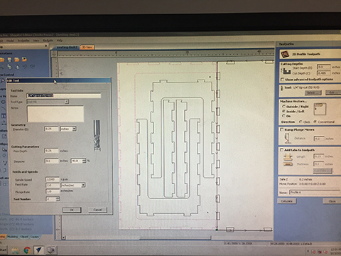
 I screwed the plywood to the sacrificial board beneath it being careful not to screw where the router would be cutting so as not to break a router bit. I used a single flute downcut bit. Instead of using vcarve to add dogbones I tried incorporating the dogbones into my design. This made the task of closing all my loops very tedious. I think it would have been easier to make the dog bones in vcarve.
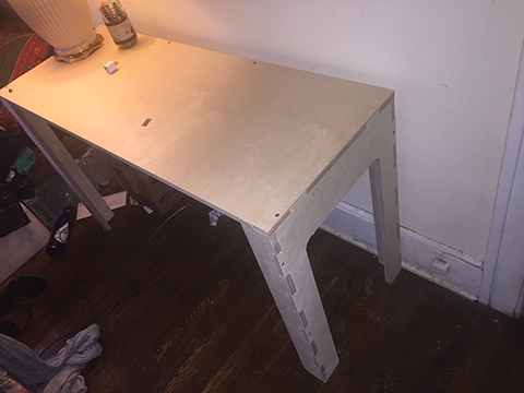
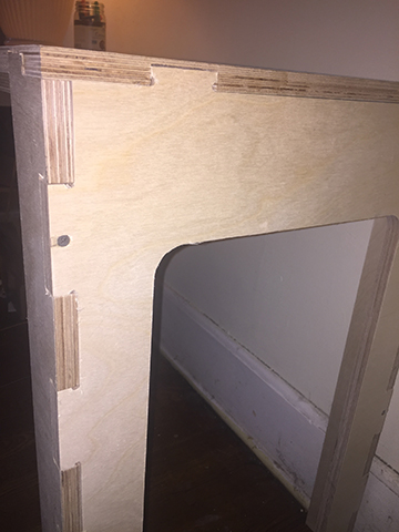
Here's the final results of my desk. It didn't come out quite as tight as I had hoped. In the future I think I would have done some test joints to get a tight press fit so i ended up using a few screws to hold everything together. I do like that if I ever moved I could take it apart very easily and make it flat.
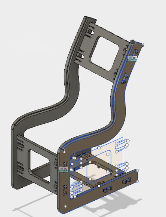
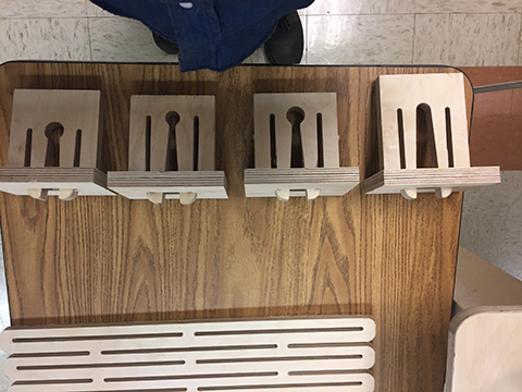
I'v been developing a chair design that incorporates wooden clips and a living hinge but i've been broke so I'v had to work lately outside the shop lately and haven't had a chance to finish it but i'll include the designs here. there's been many iterations. here's the latest ones:
This week was a real struggle. I'm really new to this kind of programming. I had a lot of help from the teachers here to help me get caught up, especially Blair. Thanks Blair!
I read this data sheet about the tiny44 chipIt was pretty hard to understand but one thing I learned was about the built in pull up resistor that holds the pin in place if you tell it to in the program
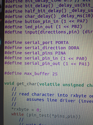
Above are the definitions that I added to neil's C code to define my pins as either a button or a led
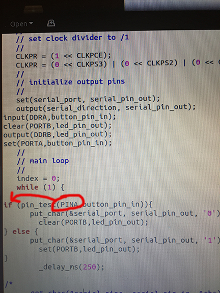
Above is the pin test within the loop. One thing I struggled with for a long time is that when writing the "if then" syntax you don't refer to the PORT but instead to the pin as I circled in the above picture
I'm working on a series of public sculpture proposals for kinetic sculptures that also function as exercise equipment. Imagine tubes emerging from the ground through which run cables attached to brass rings that you reach out to grab. As you pull on the rings it makes a puppet move! A giant life sized bear stands in front of you and swipes with it's claws! It's body can be a resonating chamber that a bass string is tightened on and a metal pick runs along it to create a roaring sound! So far all my ideas are mechanical. I'm still trying to figure out how to incorporate electronics. For my final project I'd like to 3d scan plasticine models and use cad to design the inner workings of the sculptures that I'll fabricate out of metal.
In class I will make a prototype for a kinetic sculpture that will be installed in a public park and is intended to be used by anyone who visits it in person
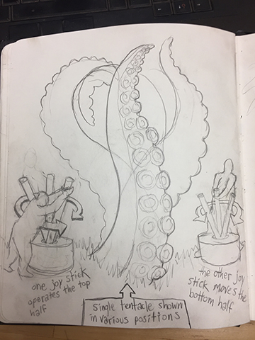
This one is a 5meter tall tentacle that is connected to 2 monument sized joysticks that are connected to it with underground cables
One joystick is connected to the bottom half of the tentacle and the other is connected to the top half of the tentacle to allow for S curves and unpredictable movements