 on Wikipedia
 Back to main page
I've some fashination for complex systems... and looking around to see pree-fit constructions, i'd discovered an old dream: to digital fabricate a Geodesic Dome....
the fascination cames from aesthetics: it's like a globe/planet/sphire...
the fascination cames from the Architecture: the interior space geometry simulates the Ozono shelter which encoloseures all the energy flutaions/transformations happening in the world: whatr condensates and goe's up in the sky, and due to the ozone layer, it cames back down as water to feed the land...
... that could be useful for
LAMP: the triangular parts as grid, which are filled by fish leather. Here's one conceptual example: Geodesic Dome designed by Alexey Koliush. Which I doenloaded
but it was a Solidworks package, not a Fusion 360 (the 3D modeling tool that I'd been studing, neither AutoCAD - the only environemt that Fab Master, my tutor, masters...>/p>
but I decided to use it to challenge my capacity of 3D modeling.
AutoCAD does not recognize the solidworks files, not the parts neither the assembly...
I'd opened the folder in Fusion 3D using the online toolbox
and got this point
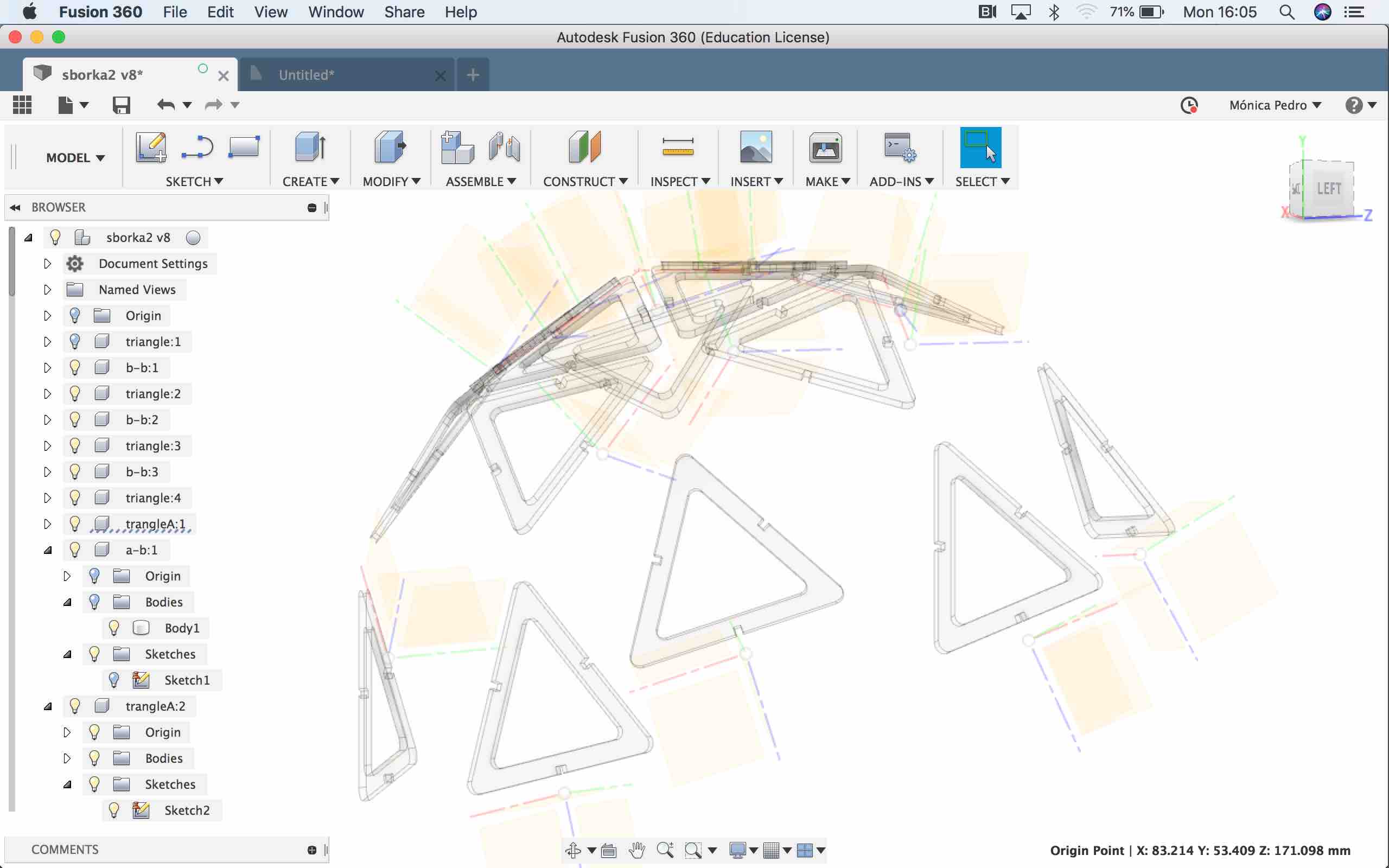
Where each of triangle and holder is a Component, made of it's own Origin and Bodie, but only a few have it's sketch, nor exists a base sketch.

QUESTION: how could I use this to laser cut the parts?
Context: the laser cutter of Fab Lab is managed by Corel Draw, so I need to be able to have 2D files with the right measures...
Problem: Fusion 360 created Design had no Assembly folder, nor exports to Corel Draw file types...
Hypotesis 1: Use the Fusion 360 Workspace DRAW to create technical draws out of each of the Components, through the option from Design on DRAW menu bar
and we have a new Fusion 360 window like this

Hypothesis 1: FAILED...
So....
got back to Model workspace and search for clues in Browser... "what if...?"
Hypotesis 2: use the SKETCH as 2D entities, but how can I access them????"
not all the Component have a Sketch, but it could be made out of the corresponding Bodie...
created a sketch out the bodie
and SAVE as the sketch to a DXF file
finaly had something to import into Corel Draw and send to laser cut
where are the first 4 triangles ....

... latter I discovered in Autodesk Learning space, this tutorial: Save as DXF
...where it explains a better Estrategy: if we have a body to laser cut, create a skect on the top or bottom of the body. The edges of that face are automatically projected into the sketch.... but we cannot be in Sketch mode...
but through this was not enough to proceed to create a lamp, since I do not know how mutch triangles are needed...
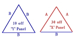
Analysing the design i discovered it's a 2 Frequency dome, which means it has two triangle types.
2F geodesic dome calculations: Geo-dome
but the connectors have a error: the measure indicates not enoy+ugh space to hold the triangles
tiangles have an extrude feature of 3.8 milimeters
connectors have a spece of 2.8 milimeters that does not sypport the thickness of the triangles
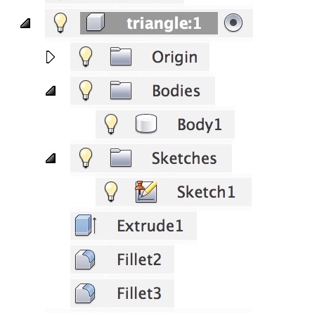
Fusion 360 has this tool that proved to be handy, which only works in Direct Modeling>, but applied to the working design identified three features on the triangle:
Conceptual model for geometry constrction:
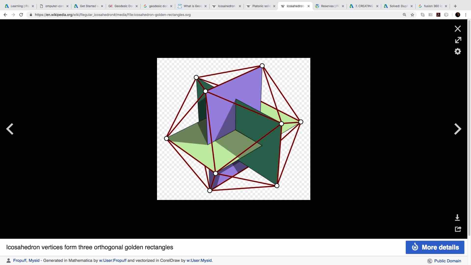
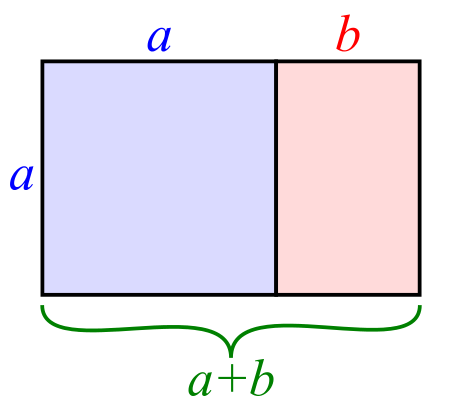
To be able to do, I'd read about the Golden Rectangle: on Wikipedia
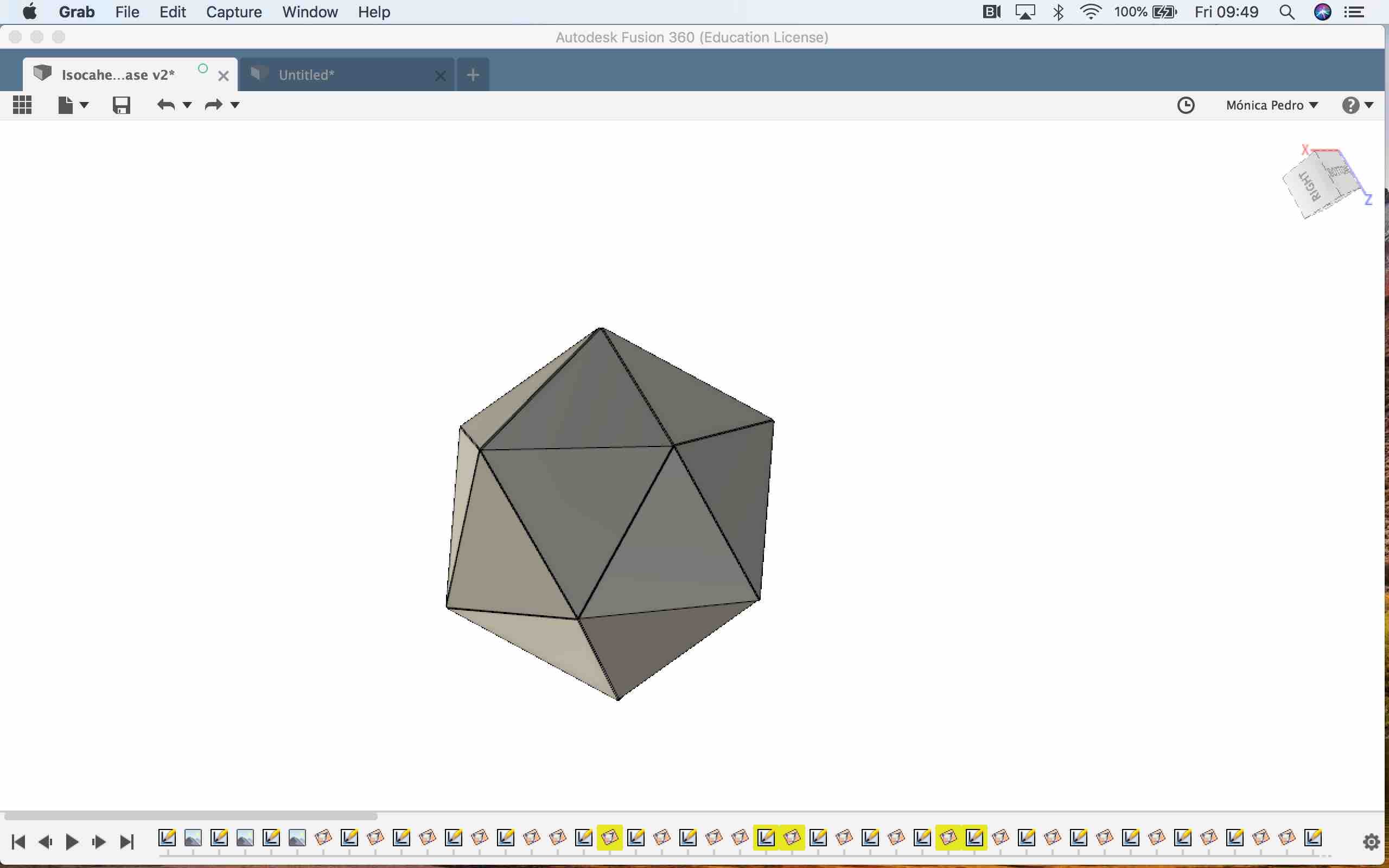
And, after many atemps to make one, I'd found a clue in a video from Adafruit that constructed all the 20 faces as sketchs due organized in 3D space, this one: 3D Hangouts - Glowing Icosahedron Resin Prints
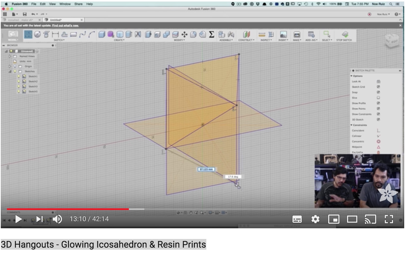
used the Include 3D Geometry to have visual clues finding the holes for the new triangles, which made that some of the vertices of the base sketch triangles where far from the base planes.. where atached to Body edges
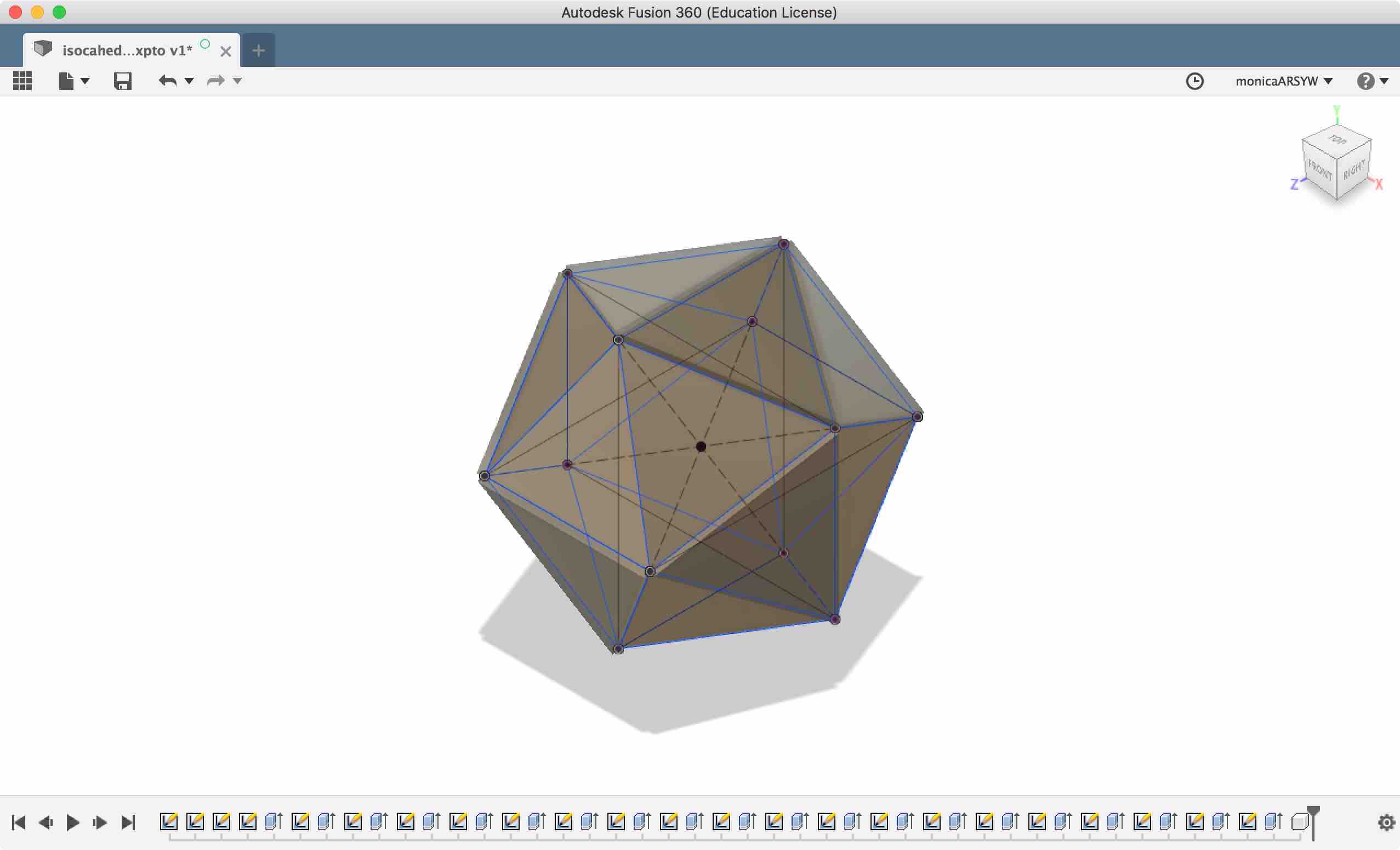
here is the resuling Fusion 360 file:
but.. to arrive here, from the file above, I'd to turn Unselectable each of the Body's being made, as follows:
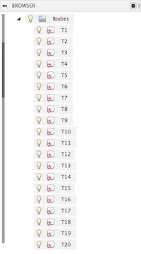
EXTRUDE all the stecks with 1mm thikness:
... but then trying the Parametric Feature - changing the base Variables got to this ERROR:
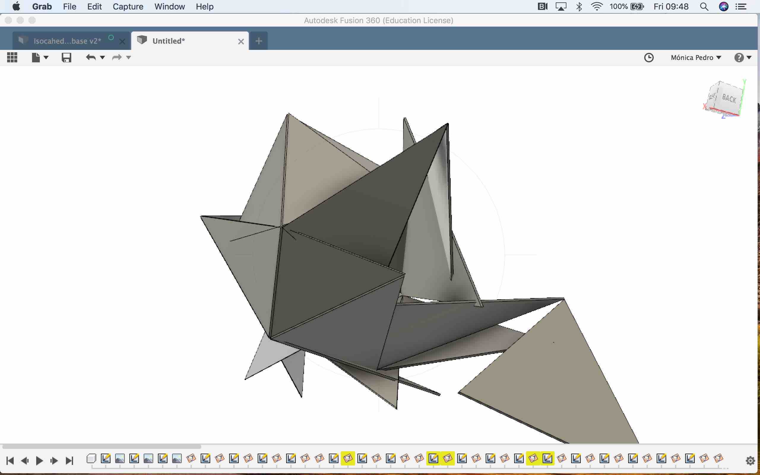
..............................................................................
but I need to study the DRAW and CAM workspaces of Fusion 360
SETUP: unity base of this workspace, is where the Machine:Type of machine we'll use, stock: the material needed, and Post-process:information to be sent to Machine
SETUP: is where you'll tell Fusion 360 what type of toolpaths to create (i.e. Milling, Turning), which Fusion models are parts, which Fusion models are fixtures and how big the raw part material will be. Fusion will help you determine the size for your raw stock, by examining the part model. You can easily add additional material to your stock model for rough cutting and work holding. Orogin lets you define where zero will be located on the part. It's easy to pick a corner, midpoint for your machining zero reference. On the Post process tab you can define the NC program number ID, add a program comment to the NC headerand select the machine Work Coordinate Offset (WCS) to use.
... so it seams that using Fusion 360, i can send works directly to any Fab Lab machine.. would that be possible???
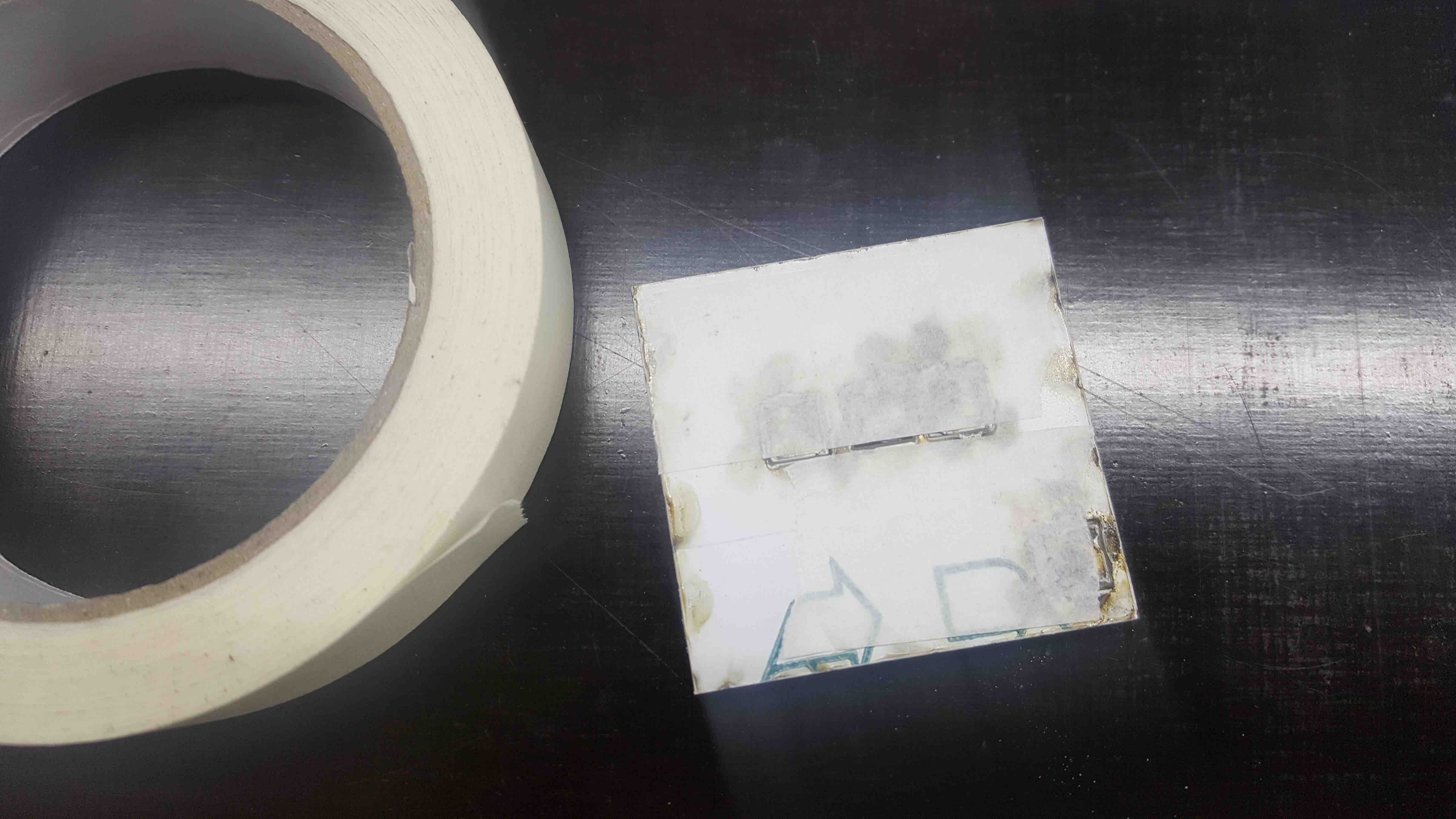
Plying with the Extension, I'll make a box with 4 different type of Hing configuration
And I draw this that you can download and make in a Laser Cut:

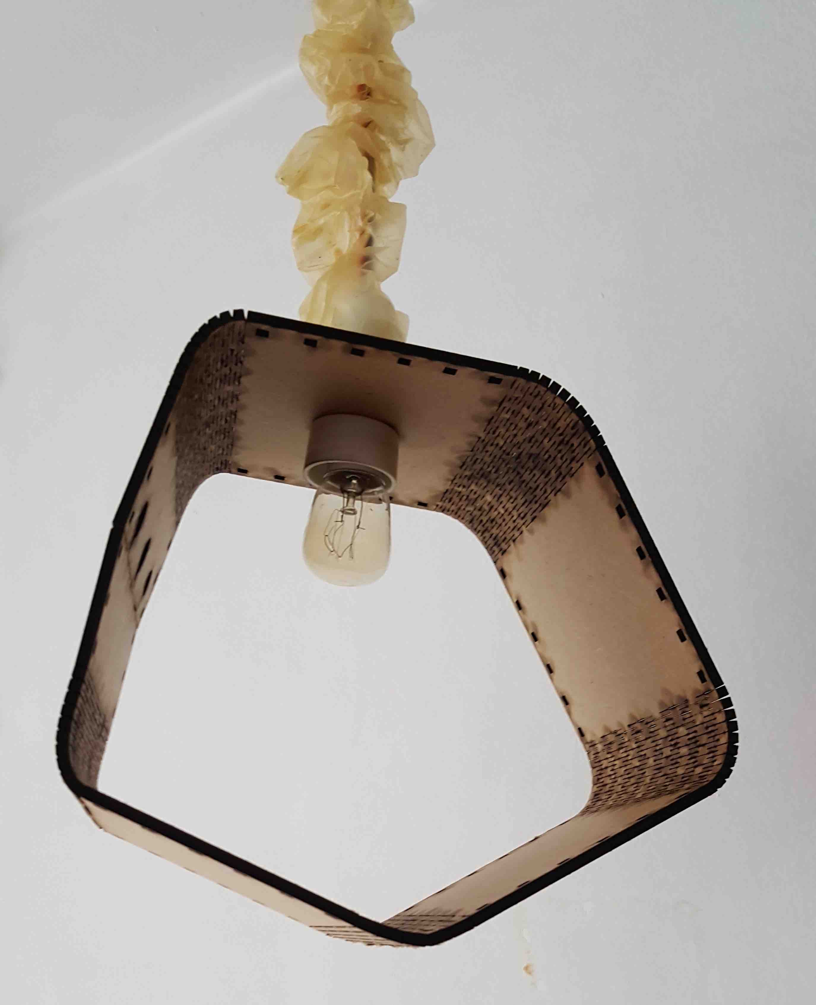
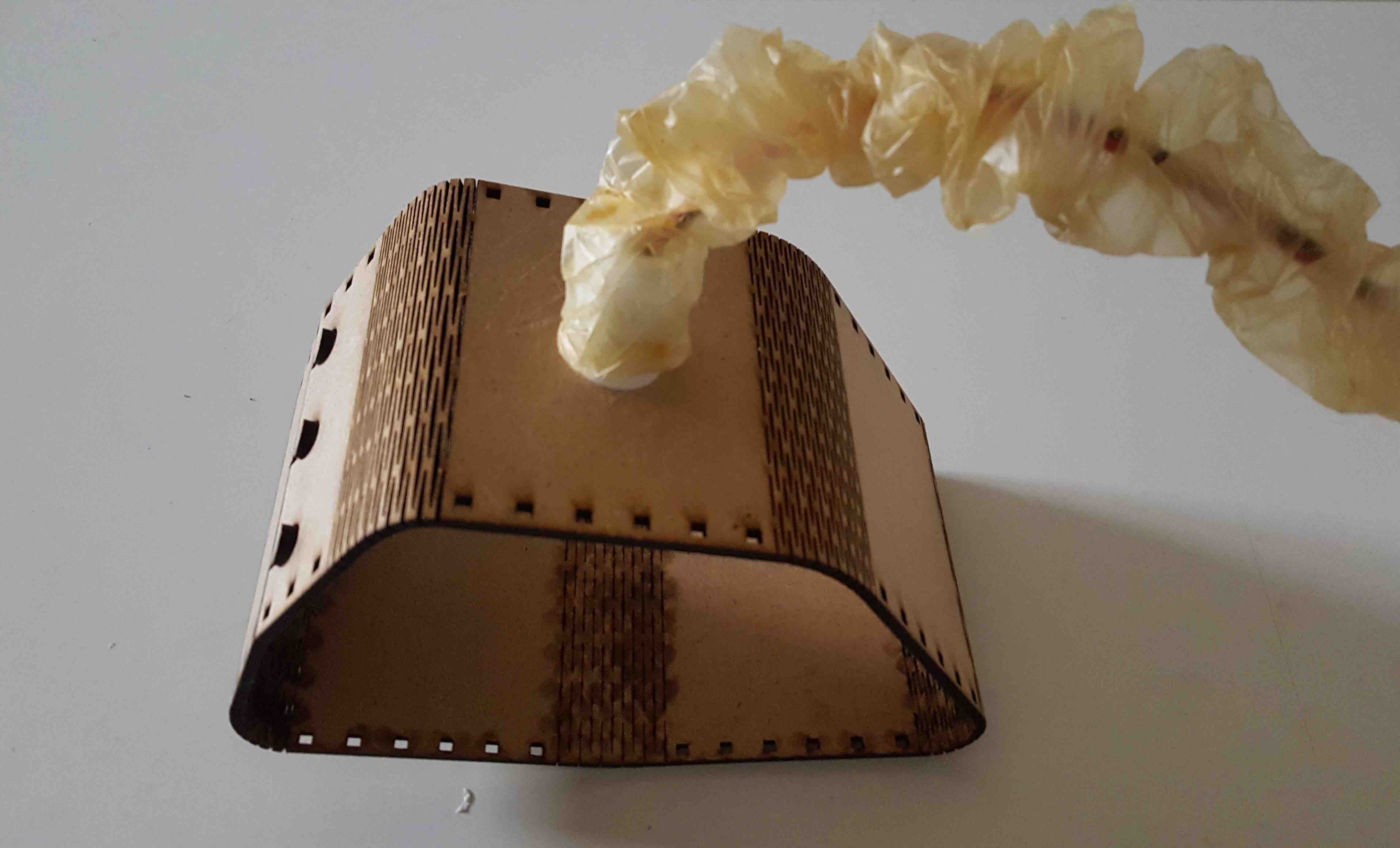
I liked so much of the result that got into making better lamps...
Good tutorial on ronded living hinges boxes.. for Laser cuttermade a table of colors to use as Masks for raster
a table of collors to cut
a table of collors to cut
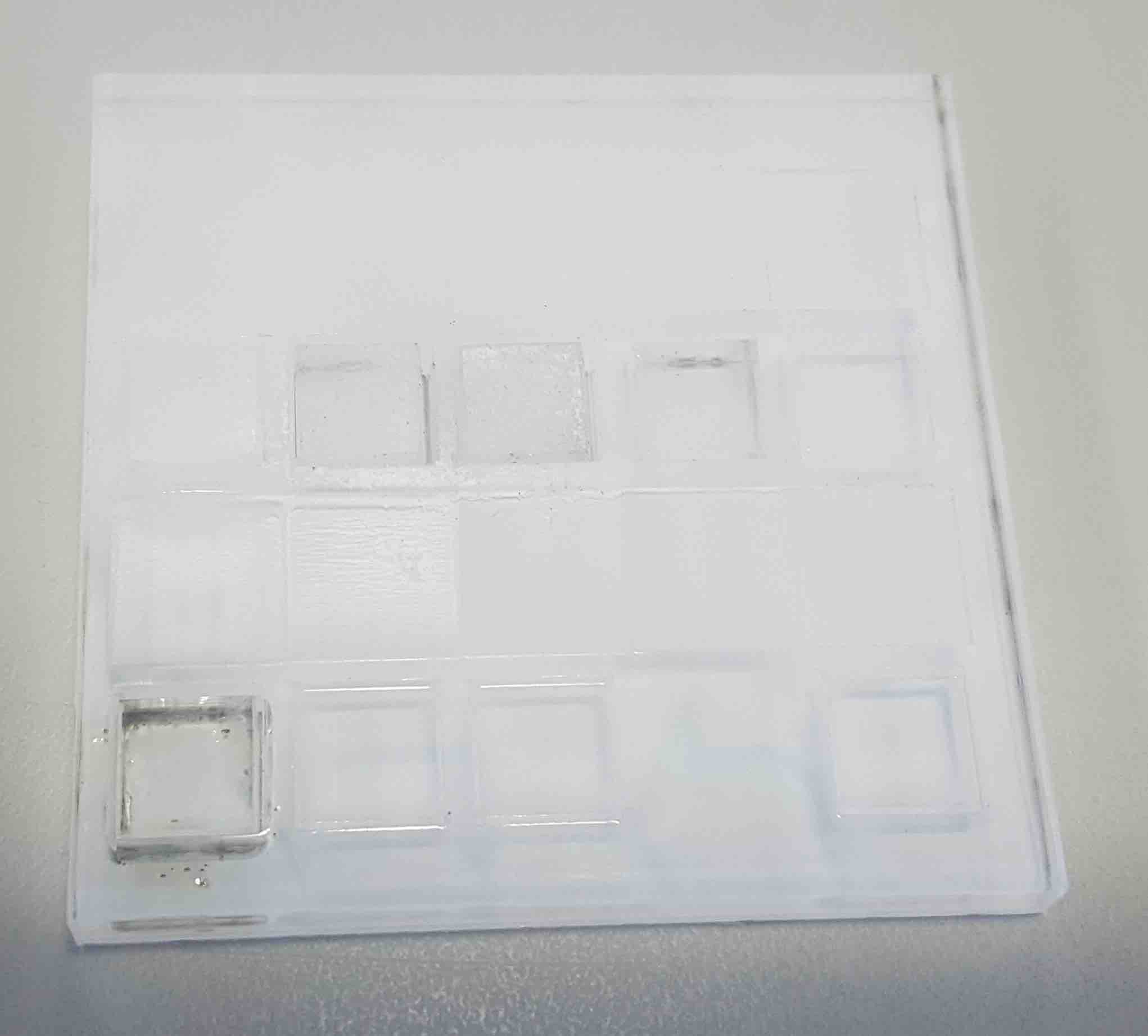
Trying Acrilyc 6mm transparent
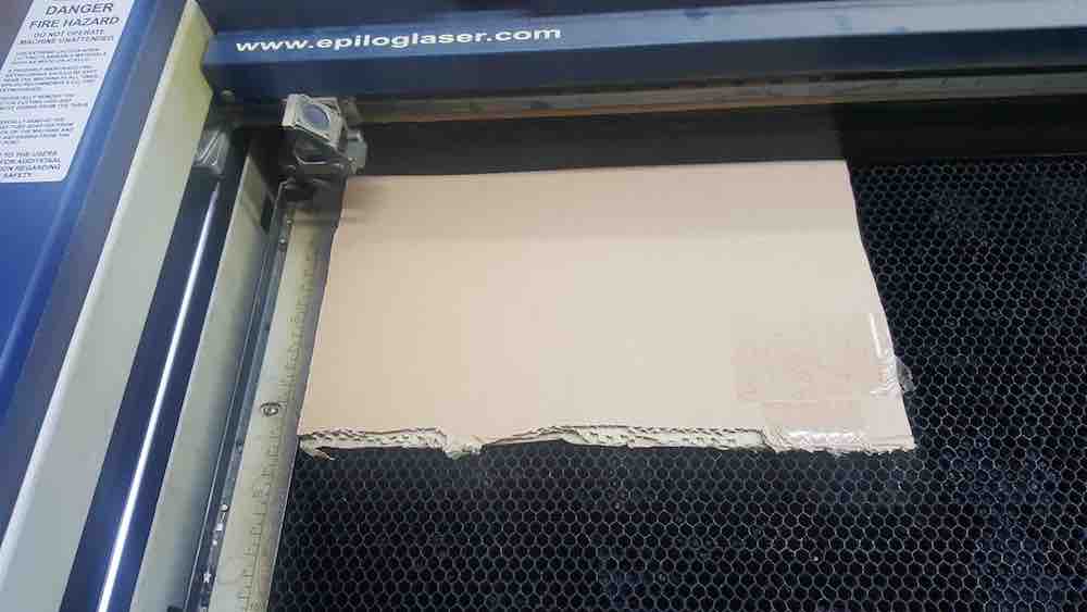
Trying Cardboard 6mm transparent
...................................................... (-).(o) ..........................................
 Creative Commons License
Except where otherwise noted, content on this site is licensed under a
Creative Commons Attribution-NonCommercial-ShareAlike 4.0 International License,by Monica Pedro.You are always welcome to contact me on monica.c.pedro@gmail.com.