Assignment 4: Computer-controller cutting
Cut something on the vinylcutter design, lasercut, and document a parametric press-fit construction kit.
Laser Cutting
Learning outcomes:
-
Demonstrate and describe parametric 2D modelling processes
-
Identify and explain processes involved in using the laser cutter.
-
Develop, evaluate and construct the final prototype
Vinyl Cutting
Learning outcomes:
-
Identify and explain processes involved in using this machine.
-
Design and create the final object
Group assignment
-
Characterize your lasercutter's focus, power, speed, rate, kerf, and joint clearance.
-
Document your work to the group work page and reflect on your individual page what you learned.

First, We researched the documentation of the FabAcademy and other sources to understand better what laser cutting and vinyl cutting consists of. We realized that each cut type is different and that they use different processes and different technology.

Then, We researched a little about laser cutting machines and the process they perform to make cuts on various surfaces. We found it interesting these machines can also make engravings on multiple types of surfaces: wood, paper, cardboard, MDF, acrylic, etc.

After that, We developed a small table that summarizes the main specifications of vinyl cutting machines. Most of the machines offer excellent performance. To choose the best machine it is necessary to take into account the size and quality of the designs that are going to be cut. Another important factor is the connectivity, the inputs, and the time it takes the machine to make the cut.

Then we plan the laser cutting tests on three surfaces or materials: wood, cardboard and acrylic. For this we make some paths with the shapes chosen for laser cutting.

To make the fit tests on an acrylic material surface, we choose the following measurements for laser cutting: 2.0 mm, 2.2 mm, 2.4 mm, 2.6 mm, 2.8 mm, 3.0 mm, 3.2 mm, 3.4 mm, 3.6 mm and 3.8 mm .

For the test on the acrylic surface, the following cutting parameters were used: frequency: 500, speed: 08, power: 94.

The laser cutter with which we carry out the tests is the Trotec Speedy 400 laser cutter. This cutter is used to cut sheet shapes or engrave the surface of wood, rubber, acrylic, MDF and other materials. The laser is designed to work a short distance from the cutting surface.

Finally, other cutting tests were carried out with the same measurements and cutting parameters.

Individual Assignment
-
Design, lasercut, and document a parametric press-fit construction kit, which can be assembled in multiple ways. Account for the lasercutter kerf.
-
Cut something on the vinylcutter.
For this assignment I decided to use the Rhinoceros and Grasshopper programs. Both programs are used to create parametric designs.
Rhinoceros is a vector CAD design software that allows creating, editing and analyzing NURBS curves and surfaces, which enables the user to freely model 3D geometries. Learning to use Rhino.
Grasshopper is a graphical algorithm editor that, as a Rhinoceros plugin, provides the necessary tools to transform it into parametric software. Learn to use Grasshopper.
I started creating a base design of a diamond with a circle in the center and with some cuts on each side of the figure.
First draw a square with measurement parameters between 50 and 70 millimeters. Then draw with circle with radio parameters between 15 and 20 millimeters.

Then I drew a four-point diamond with measurement parameters between 50 and 70 millimeters. Then I hid some lines to shape the figure.

Then I drew a rectangle on each side of the figure. Each rectangle has depth parameters between 6 and 10 millimeters and thickness parameters between 1 and 5 millimeters.

Then I checked how the object changes shape when its measurements are changed.

Then I chose the most appropriate form and generated the final object.

Finally I exported the object to the DXF format

Then I opened the object in the Corel Draw program to prepare it for the laser cutter. Then copy and paste several figures of the same type one next to the other. The separation distance was 8 millimeters..

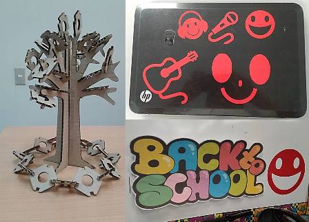
Next I designed a shape similar to that of a tree. The idea was to use the press-fit to join the previous figure with the tree. Measures of the tree: 9.7 x 27.6 cm.

Later I ordered all the figures in order to optimize the space. The total space for laser cutting was 32.4 x 98.7 cm

For the laser cutting I used the Trotec SP 400. Characteristics: 1.245 x 710 mm working area, up to 200 watts laser power, sealed off CO₂ laser
40 - 200 watts, laser safety class 2.
I chose cardboard as a cutting material because it is easier to perform the press-fit with this material.
Then I set the following parameters on the Trotec SP 500 laser cutting machine:


I had a problem with the laser cut. The laser passed more than four times on the same cutting line and burned the surface. The cause of this problem was that in the design I had superimposed several figures one on top of the other. To solve this problem I had to correct the design and try the laser cut again.

After correcting the problem I recalibrated the laser and sent the cut. In this occasion the laser cutter worked correctly.

It was very interesting to see how the laser in a few seconds could realize all the cut required by the design.

After finishing the cut I removed the pieces and ordered them in order to proceed to assemble the model

Finally, build the model with the press-fit of the pieces designed with the Corel Draw program and cut with the Trotec SP 400 laser cutter.

After this first experience I decided to create a new parametric design of a vase for artificial plants. The goal of that design was to create a more sophisticated object and improve the pressfit technique.

For this task I decided to use the Rhinoceros and Grasshopper programs. I started the design by drawing the height and the outline of the object. Rhinoceros curves were drawn to define the solid object.

The curves were loaded into one component. The parameters were placed in the components. The intersection of the planes x and y was determined..

An interior surface was generated from the intersections generated in the planes of the object..

A circular plane with a vertical orientation was built to generate the supports of the object.

The slots for the press fit between the circular figures and the supports of the object were configured.

Then I exported the 8 pieces of the object's support to the DXF format.

Then I activated in the design the final pieces in order to calculate the quantity of supplies to be used for laser cutting

Then I used the Corel Draw program to import the file.

I placed the designs in a work area of 600 x 300 mm. I tried to optimize the printing space in order to use the least possible amount of printing supplies.

The printing parameters used for laser cutting were the following:
Material: MDF (medium density fibreboard)
Resolution: 600 DPI
Job Type: Vector
Orientation: Auto Focus
Piece Size: 600 x 300 mm
Speed 16%
Power: 99%
Frequency: 827 Hz.

To make the laser cut, I used the Epilog Laser Mini machine. Wattages: 30, 40, 50 or 60 watts. Work Area: 24 "x 12" (610 x 305 mm) Materials: Wood, acrylic, glass, plastic, stone, fabric, marking metals, anodized aluminum, and more.

For the operation of the Epilog Laser Cutter, the following steps were followed:
1. Turn on the transformer
2. Turn on the motor of the air cleaner
3. Turn on the laser cutter
4. Collate the input inside the printer.
5. Send the file from the computer
6. Wait for the upload of the file sent in the control panel of the laser cutter
7. Press the "Go" button
8. Wait for the smoke generated by the laser cut to be absorbed by the vacuum cleaner
9. Remove the cut objects

Cutting circular pieces
Cutting of support pieces
After the laser cut, I removed the pieces from the work area.

I organized the pieces of the object according to their shape in order to start the assembly process.

After this I started the assembly step by step using the press fit technique.

Finally I placed the model in several shapes on a flat surface in order to analyze its balance, strength and final finish.

For the second part of the assignment I chose to continue using the Corel Draw program. First edit some images related to music.

I made sure that the images did not have fillings so they can be seen better on the vinyl cutter..

Then I added some additional images to complete the printing space. The final size of the design was 510 x 260 millimeters

Then I exported the image to the png (portable network graphics) format. This file format is the right one to be sent to the vinyl cutter

Before sending the file to the printer I gave some additional configurations to the file. For this I used the Gimp program. Gimp is a free license program.

The vinyl cutter used was the Roland CAMM-1 GS-24 Vinyl Cutter.
To use the vinyl cutter it is necessary to follow the following steps:
1. Turn on the machine.
2. Place the printing material.
3. Place the machine stops on the ends of the print material so that it is immobilized.
4. If the material is incorrectly positioned, the message "Poor position" will be displayed.
5. Upload the file.
6. Indicate the width of the printing material.
7. It will show the path of the cut that will make the machine (blue for the cut and red for the displacement)
8. Remove the material.
9. Remove the printed figures.

The vinyl cutting program was Make Png Cam and it was executed from the Linux operating system.

Then I set the following cutting parameters on the Roland CAMM-1 GS-24 Vinyl Cutter machine:

The input used was a roll of red vinyl.

Finally I used the images cut to decorate my laptop and a blackboard of a school.