MECHANICAL DESIGN, MACHINE DESIGN
MECHANICAL DESIGN
First ideas
For this group assignment several ideas of machines that could work with the axis x, y and z were proposed. Next, the documentation on the subject was reviewed in the repositories of the Fab Academy.
We are especially interested in the following examples of MIT Center for Bits and Atoms projects:
For this group assignment several ideas of machines that could work with the axis x, y and z were proposed. Next, the documentation on the subject was reviewed in the repositories of the Fab Academy.
We are especially interested in the following examples of MIT Center for Bits and Atoms projects:
- Machines that make: cardboard stages: click here
- CNC Hotwire foam cutter demo: click here
- Reconfigurable stages: click here
- MTM-LJ (“Little John”) click here
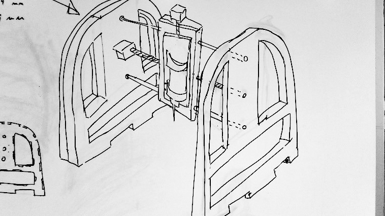
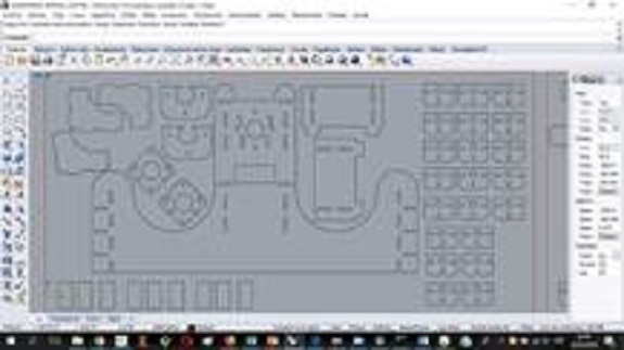
After making several drawings in draft it was agreed that the best option was to design a recording machine. This machine must record information on a bed of acrylic material. To make the engraving the machine must move on the axes: X, Y and Z:
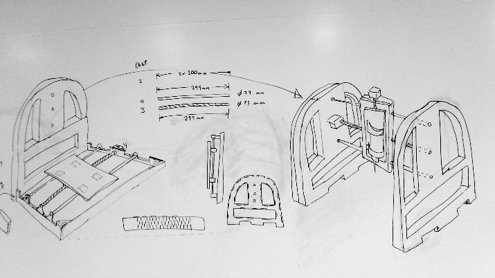
The engraver of the machine must move in the three axes to carry out the engraving works on a transparent acrylic surface. The engraver will need a structure that supports it and allows it to move around the three axes.

Materials
The materials that would be necessary for the structure, the mechanical part and the electronic part of the machine were defined:
For this assignment we require the following materials:
- (3) NEMA 17 Stepper motor 12V For CNC Reprap 3D printer extruder 36oz-in 26Ncm 0.4A
- (6) 100-500mm 15mm CNC 3D Printer Axis Chromed Smooth Rod Steel Linear Rail Shaft
- (3) 8mm screw screw stainless steel ball 3d + t8 printer 300-600mm nut
- (6) pcs KP08 P08 Acme Lead screw Assembly bearing Support For 8mm CNC Reprap 3D
- (6) Sc8uu 8mm support bearing linear rail shaft bearing lm8uu CNC sp 3d printer
- (6) pcs Linear Bearing Slide Block CNC SCS8UU 8mm Shaft for 3D Printer RepRap TE730
- (7) MDF sheets
- (3) Gestalt Nodes
- (1) FabNet Board RS-485
| Sc8uu 8mm support bearing linear rail shaft bearing lm8uu CNC sp 3d printer | 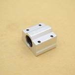 |
| pcs Linear Bearing Slide Block CNC SCS8UU 8mm Shaft for 3D Printer RepRap TE730 | 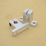 |
| NEMA 17 Stepper motor 12V For CNC Reprap 3D printer extruder 36oz-in 26Ncm 0.4A | 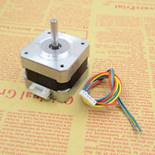 |
| 8mm screw screw stainless steel ball 3d + t8 printer 300-600mm nut | 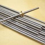 |
| 8mm screw screw stainless steel ball 3d + t8 printer 300-600mm nut | 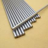 |
| pcs KP08 P08 Acme Lead screw Assembly bearing Support For 8mm CNC Reprap 3D | 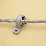 |
| MDF sheets | 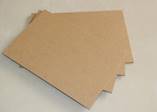 |
| Octopus electric engraver 270. | 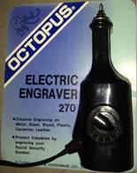 |
Design of the structure of the engravermachine
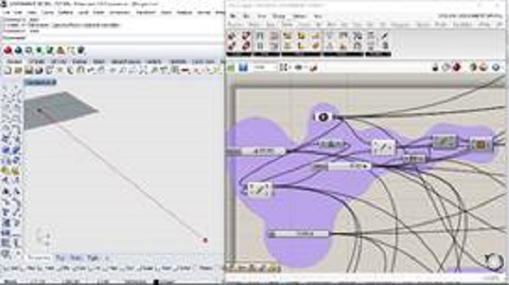
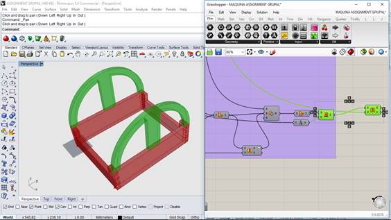
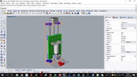
The Rhinoceros program and the Grasshopper plug-in were used to design the structure of the Engraver machine.
The Rhinoceros program and the Grasshopper plug-in were used to design the structure of the Engraver machine.
Steps:
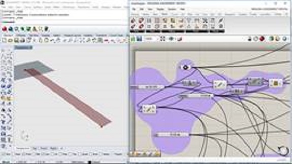
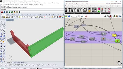
Step 1: Define a point on the surface of the Rhinoceros program
Step 2: Develop the first construction axis (X axis)).
Step 1: Define a point on the surface of the Rhinoceros program
Step 2: Develop the first construction axis (X axis)).
Step 3: Develop the first base surface for the initial part that will support the motor and the bearing.
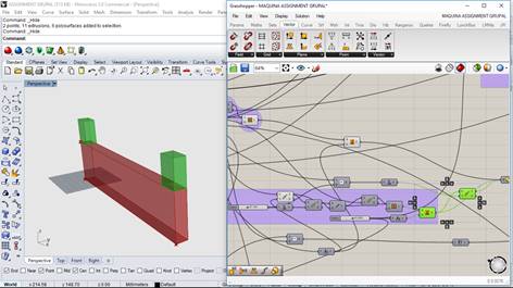
Step 4: Generate the block with the surface.
Step 5: Generate the reinforcements (green), these reinforcements are also useful to have depth in the part to install the engines the bearing.
Step 5: Generate the reinforcements (green), these reinforcements are also useful to have depth in the part to install the engines the bearing.
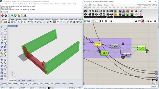
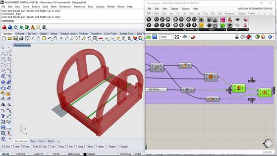
Step 6: Create a line for the piece on the second axis.
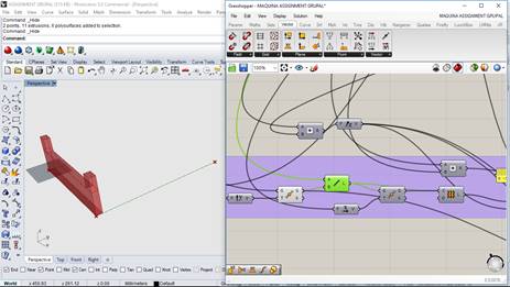
Step 7: Develop the surface that will be the basis of the new piece on the Y axis
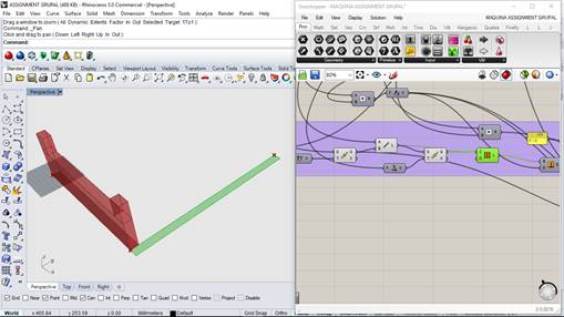
Step 8: Develop piece Y considering the total height of the piece on the X axis.
Step 9: Create the second base part of the Y axis
Step 10: Develop encounters on the X axis
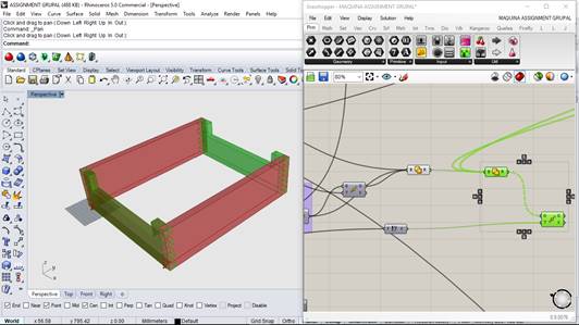
Step 11: Develop the arcs to incorporate the head

Step 12: Use the green regions to create gaps that allow the figure to be manufactured.
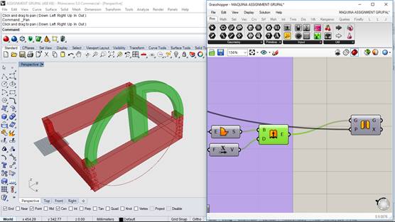
Step 13: Develop the second arc that completes the piece that is in the second position of the Y axis.
Step 14: Develop the definition of the metal rods to get an idea of the position they would occupy in the machine.
Cutting and design tests
First, some trial cuts were made with the shopbot machine cutting 18 mm mdf. The tests were to measure the fit and resistance of the machine.
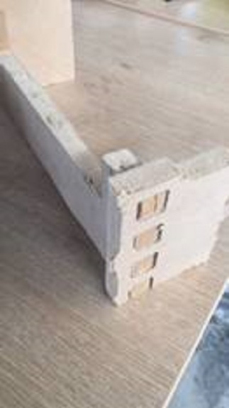
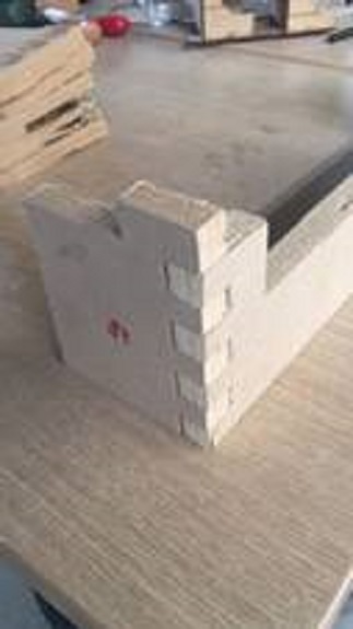
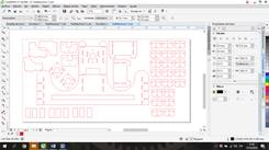
It was decided to use as input for the manufacture of the 3 mm mdf structure because it is easier and quicker to assemble the parts of the structure of the engraving machine.
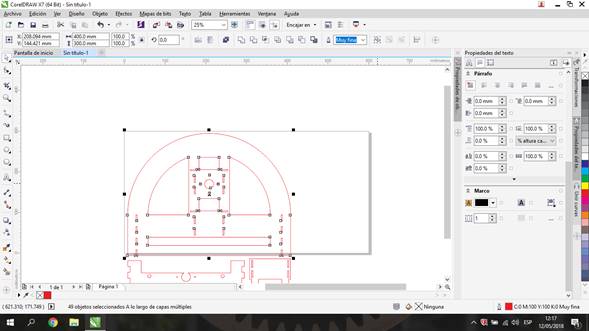
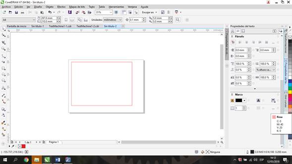
The design of the structure was modified by removing the arches due to the fact that they did not fit in the mdf plates for laser cutting
The design of the structure was modified by removing the arches due to the fact that they did not fit in the mdf plates for laser cutting
Original design:
Modified design:
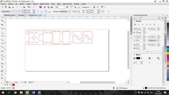
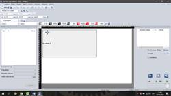
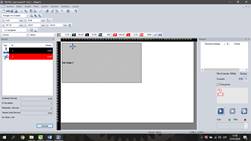
Some laser cut tests were performed to confirm that the design was of the correct size. The laser cut was made with the Trotec Speedy 400 machine:
Test 1
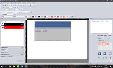
Test 2
Test 3
There were some problems with the fitting of the pieces in the test cut. The measures were modified and a new test was sent again. Finally the problem was solved.
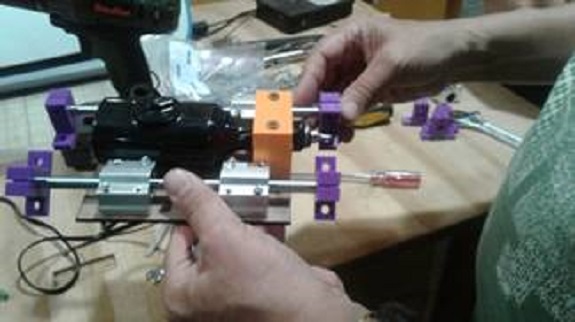
Then some pieces fitting tests were done with the motors of the engraving machine

then the design of the engraving base was made
Design of the structure of the x, y and z axes of the engraving machine
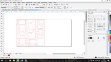
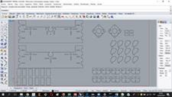
Then the pieces of the structure of the machine were designed using the Rhinoceros program and the Grasshopper plugin
Then the pieces of the structure of the machine were designed using the Rhinoceros program and the Grasshopper plugin
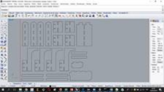
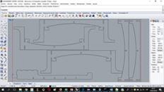
Then the design of the Z-axis structure of the recording machine was made using the Rhinoceros program and the Grasshopper plugin
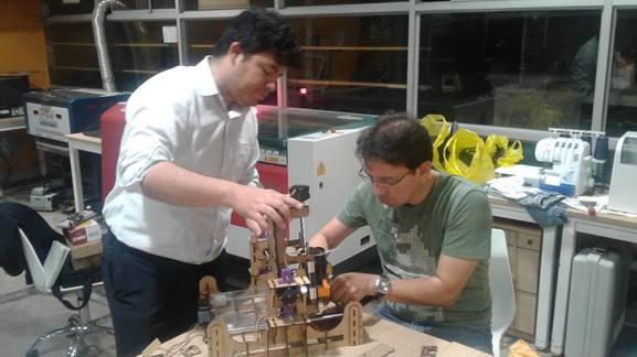
Cutting and assembly of the recording machine
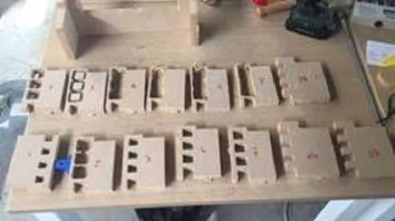
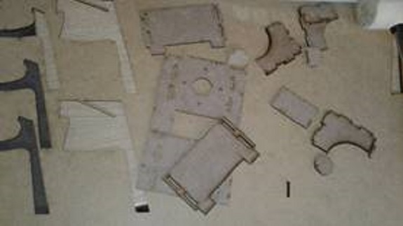
After the tests and the final design of the pieces were carried out, each of the pieces was cut using the Trotec Speedy 400 machine.
After the tests and the final design of the pieces were carried out, each of the pieces was cut using the Trotec Speedy 400 machine.

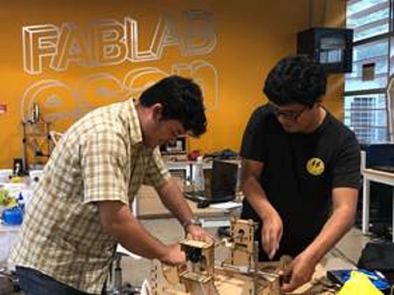
Then the structure of the base of the recording machine was assembled
Then the bed was screwed to the structure:
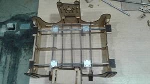
After that, supports were placed at the corners of the structure to make it more stable
supports for the steel rods were placed on the axes x and y of the structure:

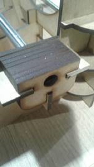
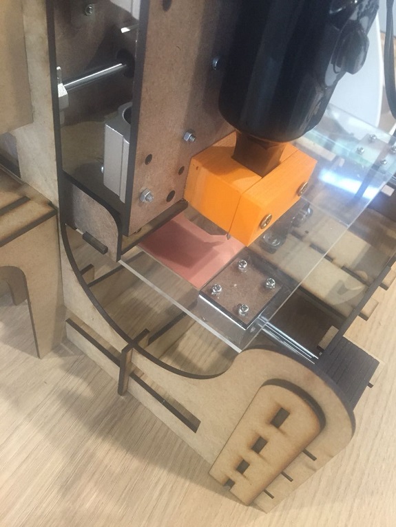
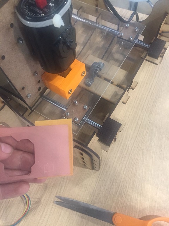
then the machine head was assembled
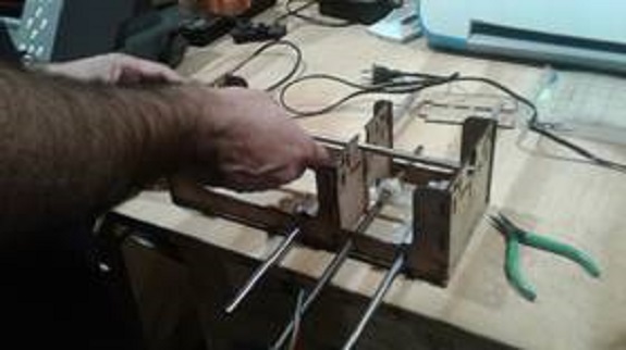
For the head it was necessary to use supports for the 8 mm metal rods
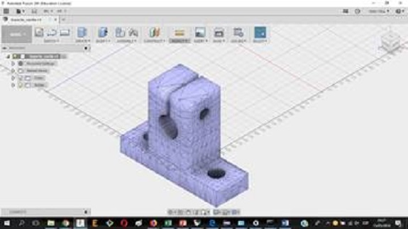
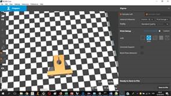
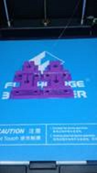
then the metal rod holders were printed on the Flashforge printer
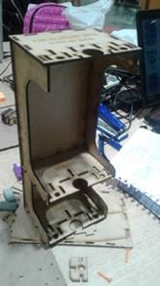
Then proceeded to assemble the platform for the recorder (Z axis)

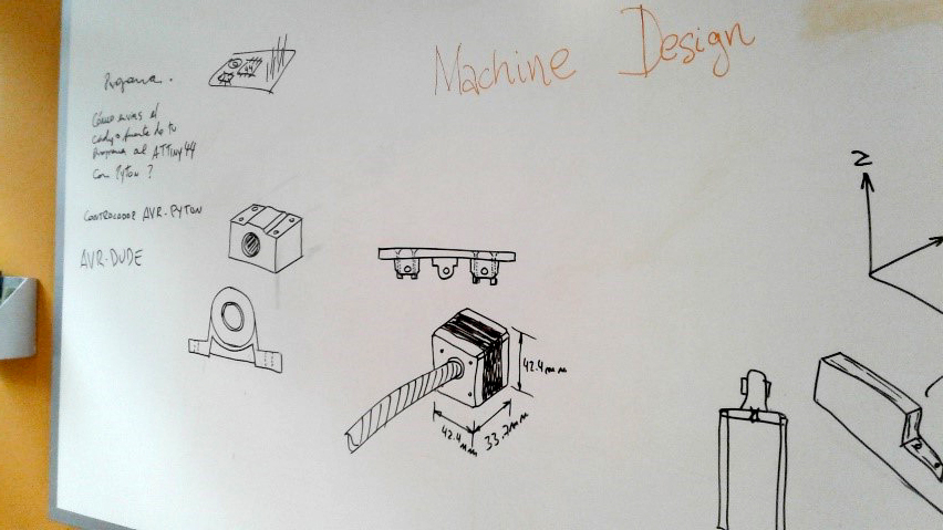
MACHINE DESIGN
FabNet Board – Materials
- (2) 590 OHM RESISTOR. RHM590FCT-ND
- (1) 2x4 PIN HEADER
- (2) 2x2 PIN HEADER
- (1) 2x4 PIN RECEPTACLE. 649-71600-008LF
- (2) 2x2 PIN RECEPTACLE. 649-71600-004LF
- (1) FABNET ADAPTOR BOARD
- (1) USB->RS485 CABLE
- (1) 12V 5A SWITCHING SUPPLY
- (1) 24V 3.8A SWITCHING SUPPLY
- (1) 7.5V 5.3A SWITCHING SUPPLY
- (2) POWER CABLE, US
- (2) POWER CABLE, UK
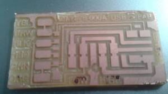
Milling board
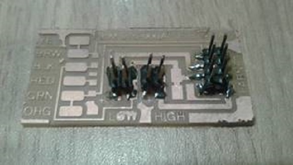
Welding components
.
Operation test of X axis
Operation test of Y axis
Operation test of Z axis
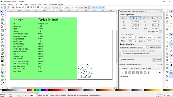
Test of operation of the three axes, make a spiral on copper foil.