Computer Controlled Machining Router
Assignment 8
So This assignment is to do :
group assignment
test runout, alignment, speeds, feeds, and toolpaths for your machine
individual assignment
make something big
So I already designed a Chair in CAD Assignment .. and That is it .. You are going to find the design here ..
Assignment 3 / CAD
Then I exported a File DXF and Waiting to design ..
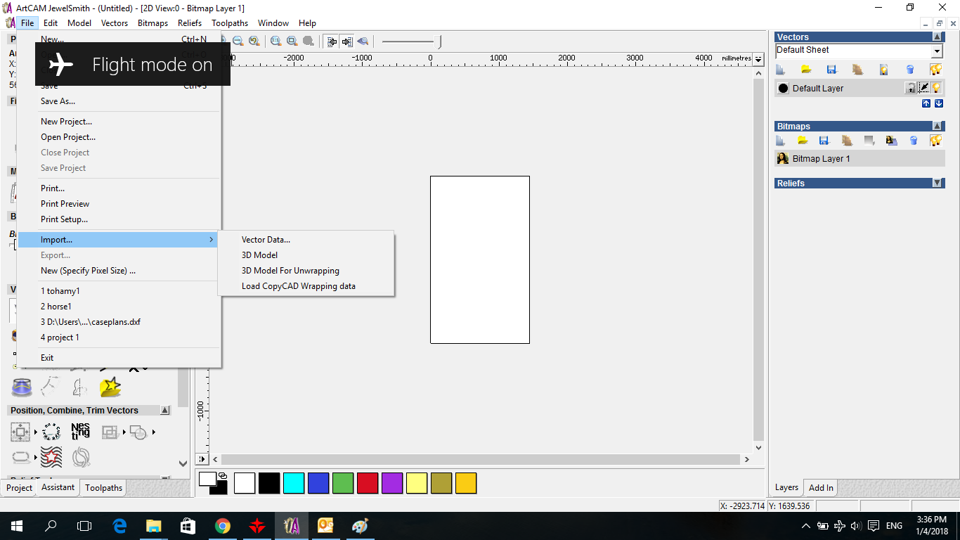
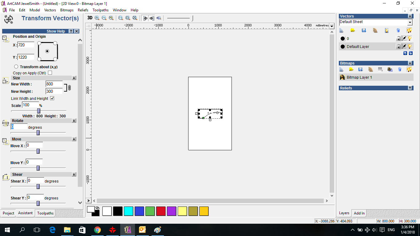
Then I start using ARTCAM for the Router .. This is ARTCAM ..
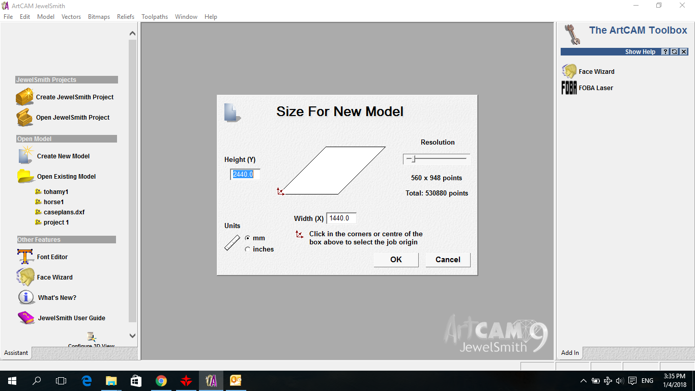
First thing I start import my DXF File Started with the LEG DXF
Here i started to rotate it to fit in the sheet ..
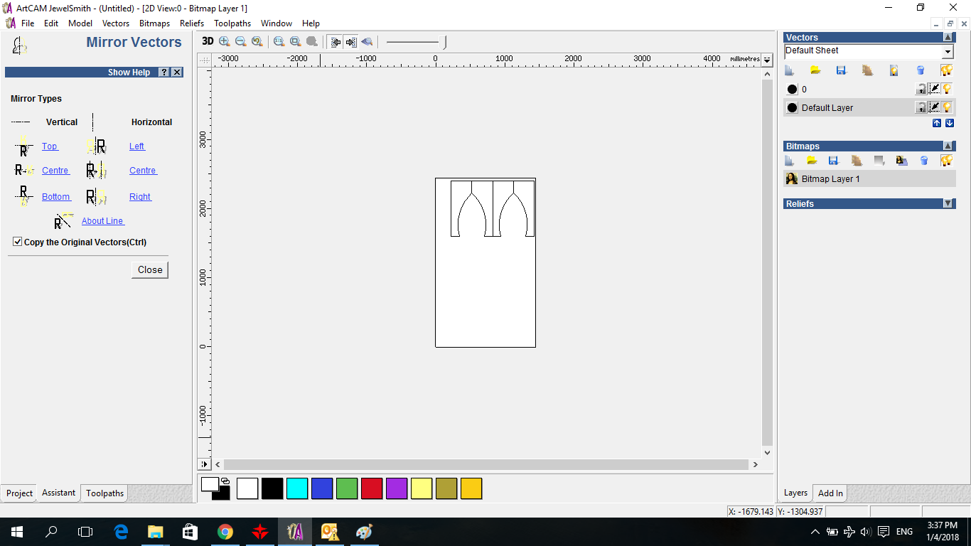
Then I start making Mirroring for the Leg 3 times to get 4 Legs
Then I imported the CIRCLE DXF
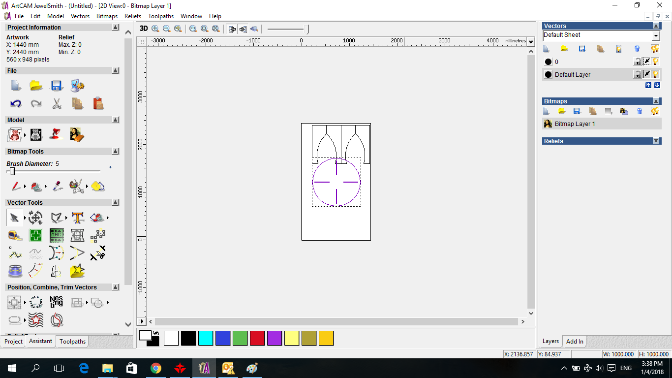
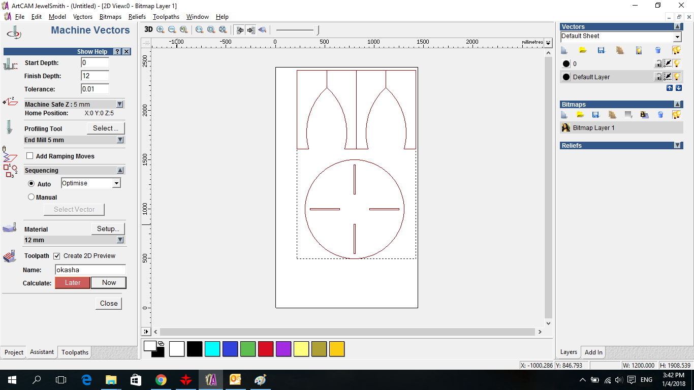
Finalize the Postion of Everything .. Then we select the Toolpath down left the secreen ..
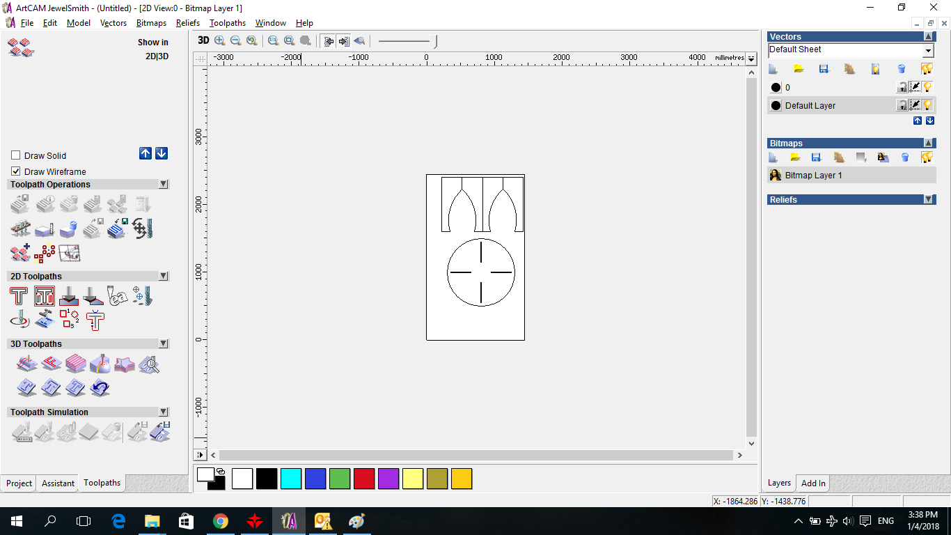
And we start using the machine cut Vector .. We determine the Depth which is 12mm Select the End Mill We will use we have in our lab 5 mm End Mill and Select the material that it is thickness is 12 mm and name the file and make calculate NOW
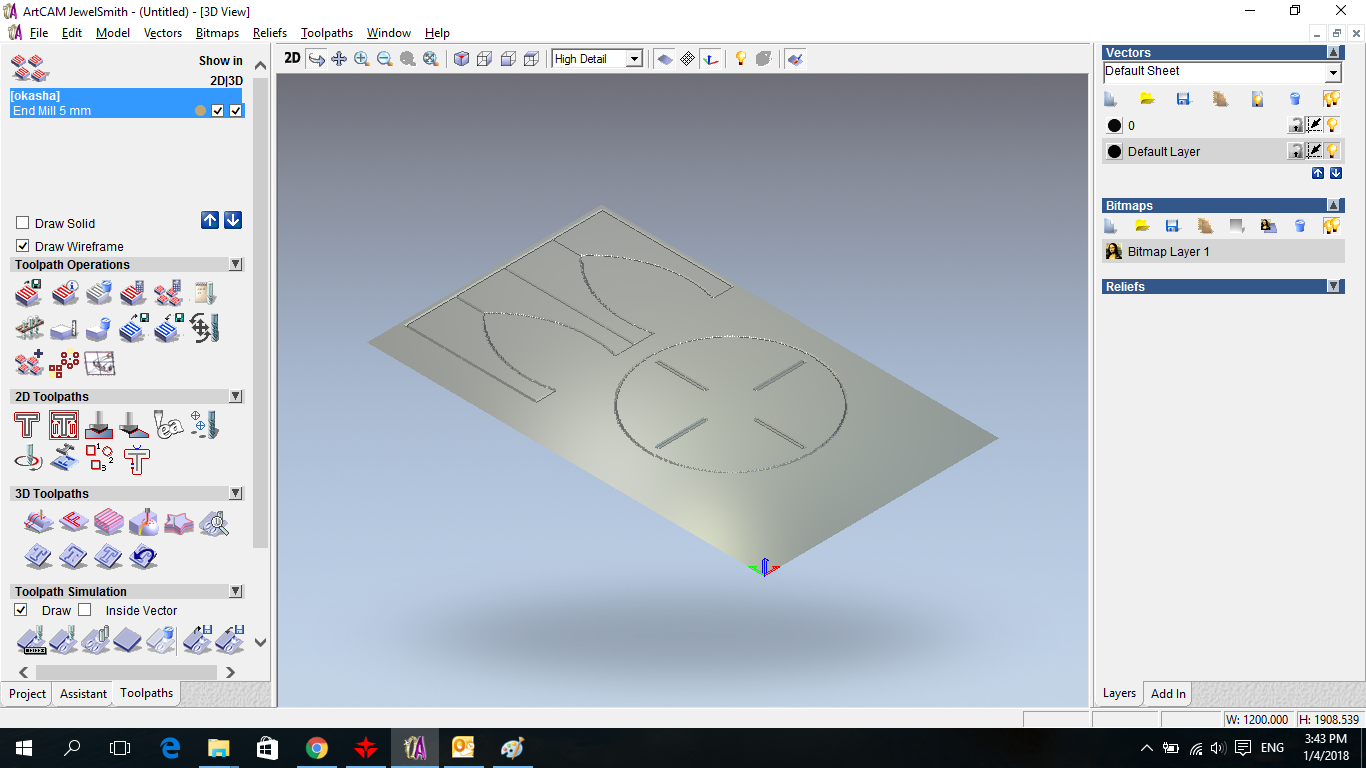
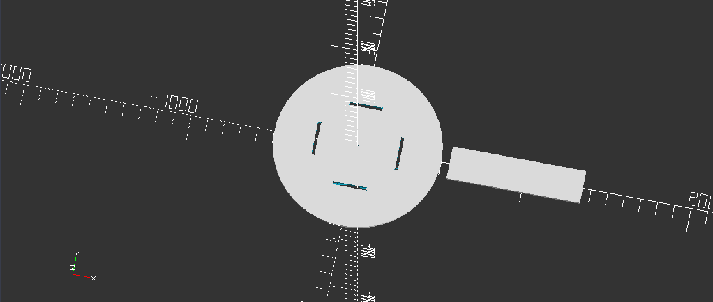
Here is Simulation for the Cut
Then we make Save for the ToolPath and that is the File for the router to use .
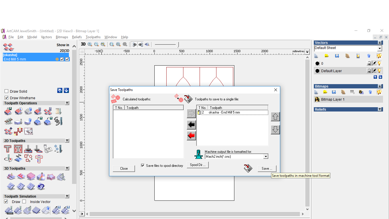
The file for the Router Machine .. ==> OKASHA CNC
As I forget to Make a Dogbone So i have to make a new design .. As I fall in Love with Openscad So I decided to use it :D :D
wt = 18 ; // Wood Thickness
lh = 800; // Leg Height
dog = 3 ;  //  dogbone = half of the bit
cr = 500 ; // circle raduis
places = [[250,-0],[-250,0],[0,250],[-0,-250]]; // Slots places
x = 18 ;  // The x length
kerf = 0 ;
y = 200 ; // The y length
dim = [[x,y],[x,y],[y,x],[y,x]]; // orientations for the slots


difference(){
 linear_extrude(height = wt, center = true, convexity = 100, twist = 0,$fn = 100)
 {
     circle(r=cr);
 }
 linear_extrude(height = wt, center = true, convexity = 100, twist = 0,$fn = 100)
 { //    translate([20,0, 0])

for (j =[0:4])
{
cutpiecex=places[j][0];
cutpiecey=places[j][1];
x=dim[j][0];
y=dim[j][1];
cut_piece = [
     [cutpiecex-(x/2)+kerf/2,cutpiecey-(y/2)+kerf/2],
     [cutpiecex+(x/2)-kerf/2,cutpiecey-(y/2)+kerf/2],
     [cutpiecex+(x/2)-kerf/2,cutpiecey+(y/2)-kerf/2],
     [cutpiecex-(x/2)+kerf/2,cutpiecey+(y/2)-kerf/2]];
polygon (cut_piece);
     i = 0 ;
for (i =[0:4])     {
     translate(cut_piece[i])
     circle(dog);
}
     }
 }}
    linear_extrude(height = wt, center = true, convexity = 100, twist = 0,$fn = 100)
{
  translate([700,5]) {
      cutpiecex=places[0][0];
    cutpiecey=places[0][1];
    x=lh; // length of the leg
    y=200; //
      cut_piece = [
     [cutpiecex-(x/2)+kerf/2,cutpiecey-(y/2)+kerf/2],
     [cutpiecex+(x/2)-kerf/2,cutpiecey-(y/2)+kerf/2],
     [cutpiecex+(x/2)-kerf/2,cutpiecey+(y/2)-kerf/2],
     [cutpiecex-(x/2)+kerf/2,cutpiecey+(y/2)-kerf/2]];
      polygon (cut_piece);

      }


  }
Which this code Generate this
And this is the machining phase
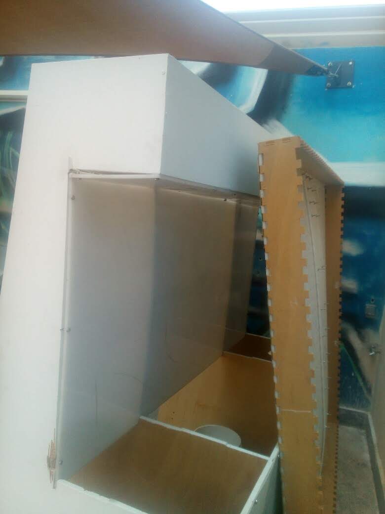
The hardest part of the machining is Fixing the sheet ..

There are a sacrificial layer must be there to protect the Bit you will use from hit the Metal of the machine ..
Then the origin Adjusting the Origin is Very important to Can use the Full Sheet and not to get out of the sheet .. I learnt two ways ..
Engineers Way in our lab .. is everytime we Set the sheet and Adjust origin by moving the machine to origin and adjust the sheet depend on that ..
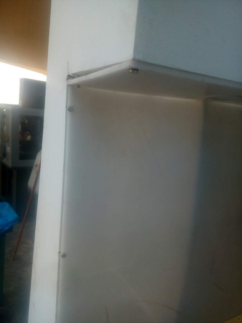
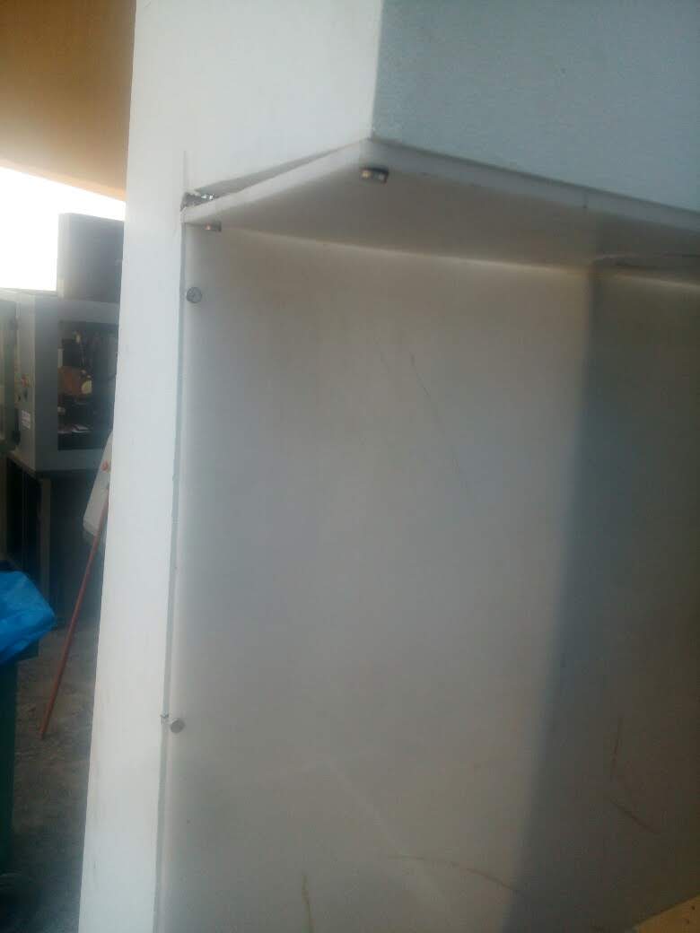
There are another way That I learnt from Technician .. He put from the first time working with the machine a angles 90 on 3 Corners each on thickness is 6 mm to can hold the sheet which fixed to sacrificial layer with nails ..
Also It is outside the working area of the machine When you adjust the sheet you need to work with with those angles the start of the sheet automatic will be the zero origin of the machine .. This is Almost clear at the Video of the Machining ..
For the Z In the lab We adjust z Manual ..
In the Workshop they have automatic Z Leveling ..
both put nails in the corners .. to fix the sheet and if there small pieces we also put nails on them ..
About the Bit we used .. We used Endmill that made for wood 6 mm..
also I withnessed breaking a Bit because it hit a Nail .. And the bit we were using is 4 mm at the End at the top 6 mm Endmill ..
For Feedrate : Both Machines was used as the software initial them
4000mm/min
For Spindle Rev : The lab was 7000 Because we work with a Heavy Wood need high Spindle Speed
For the Workshop We workded with MDF THe Spindle was 5500 Because MDF more easy to cut ..
And then Everytime start working shift the machine
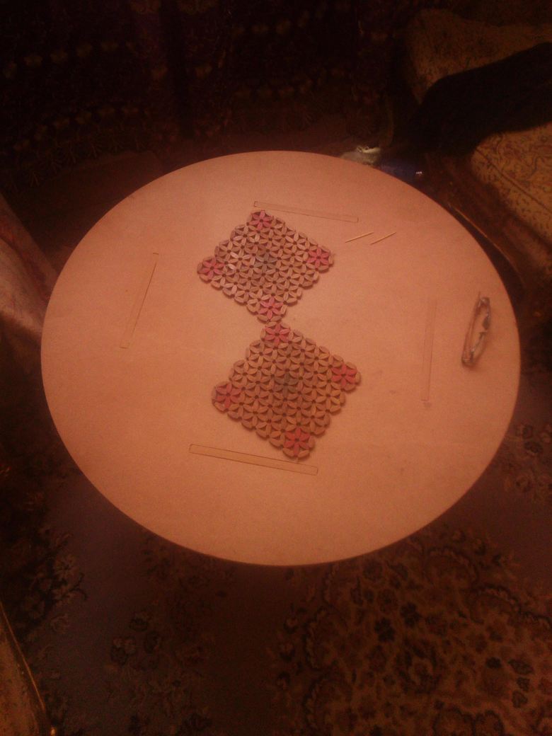
Here is the table with a touch from Mom :)
Areas to Improve my skills ..
I will invest more time after academy with openscad that it is going to help me draw a standard shape with equations and start trasform it by changing parameters ..
I will work try try another Materials like Acrilyic and artylon .
#Update
For Testing acrylic ..
Funny fact , I made my design at a workshop not in a lab .. The owner of the workshop wanted to buy this talble from me :D
as It looks great the MDF wood and Very Cheap and Good to use ..
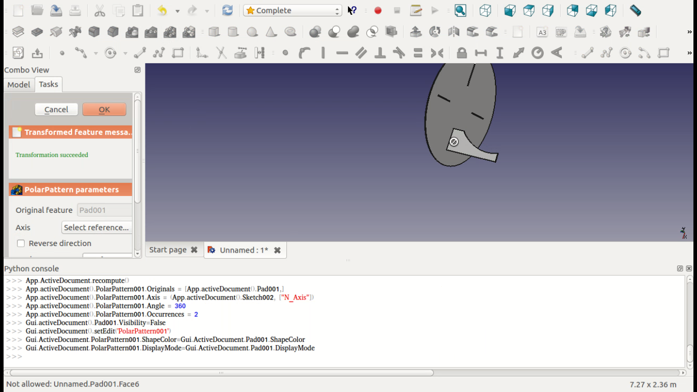
I decided also to Try 3D modeling on Router So I tried to test turn a photo 2D to 3D Through the program ..
I try 3D modeling option on ARTCAM on the Machine ..
So I followed this Video as I want to have some fun with doing 3D thing ..
The Video is Great to Follow .. But for the concept of Transforming the Images to 3D design ..
Artcam use the colors to give it Height .. and there are 3 Types of Height a Sphere , Pyramid and Box Heights to limit ..
and it is so easy to use ..
The Machining Phase
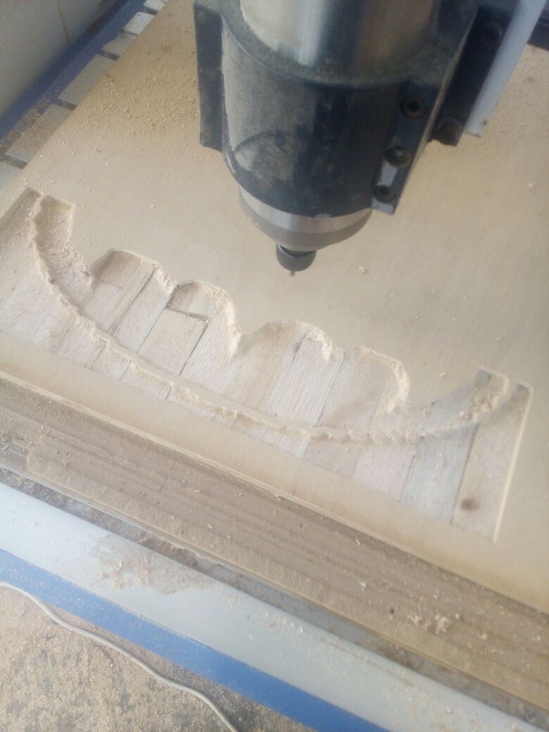
While Working :)
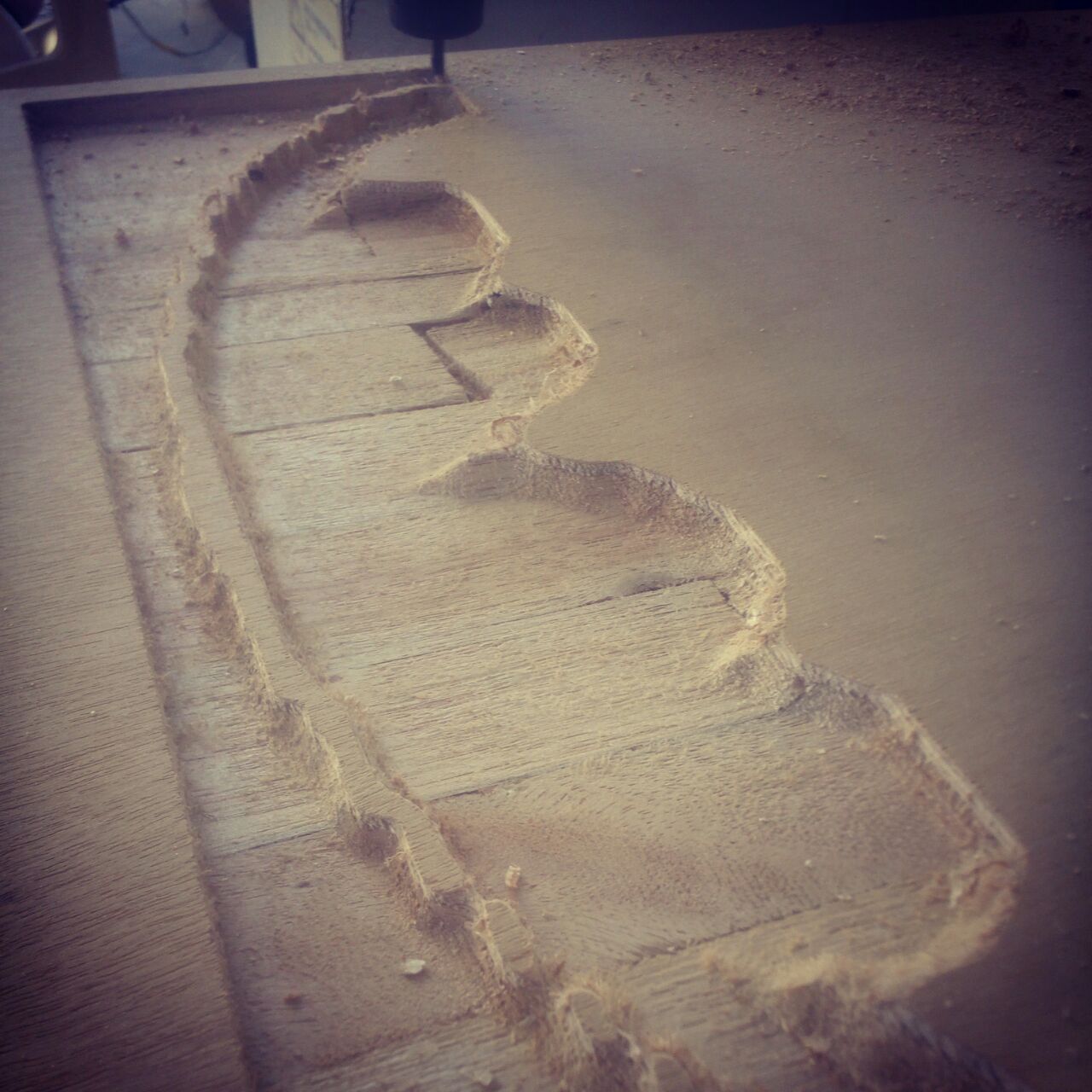
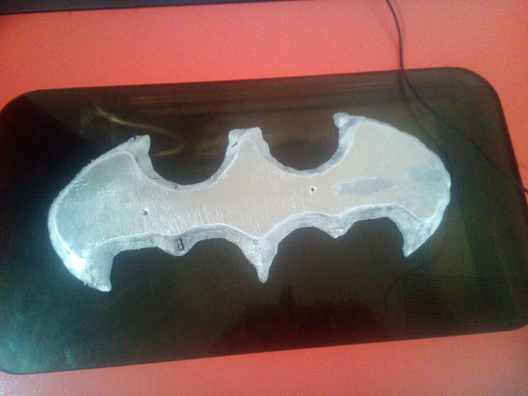
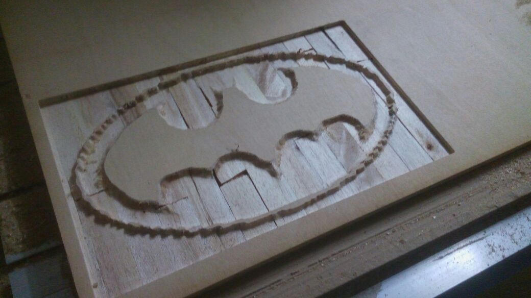
After Finishing
After paint it :D and On the laser cutter :)
The Difference between 2D and 3D is the Time spending to make 3D design on the Router with just Roughing Phase It didnt make Finishing .. as it took 4 Ours in just Roughing as Depth of wood is 18 mm .
for my trial with 3D next time I will try to reduce the speed of the Roughing as the wood was wery weak and it is damaged because of the feedrate and spindle speed ..
Here is Some questions From My global Evualutor :
Q) How you selected the cutter to use ?
Indeed I worked on 2 Routers the difference between both are :
1) Lab one has 1 Head working with her own Interface
2) Workshop one has 2 Heads working using Mech3 With lovely Interface and have good shortcuts to work with .. It has also automatic z Leveling
Q) what setting were appropriate for your material ?
I used Artcam Settings In the 2 Machines ..
I didnt Change it But Let me illustrate what are the parameters are ..
In this Link from Autodesk you are going to find all Details you need ..
Autodesk Artcam Parameters
1) Stepover — Enter the distance between adjacent machining passes.
2) Stepdown — Enter a tool's maximum cutting depth. The stepdown generates multiple machining passes.
3) Feed Rate — Enter the speed that the tool moves in relation to the material block.
4) Plunge Rate — Enter the speed at which the tool moves in the Z direction when it plunges into the material block.
5) Spindle Speed — Specify the rotational speed of the spindle. The spindle is the part of the machine tool that rotates during operation. On a mill it holds the tool in position. On a lathe it holds the material block.
6) Tool Number — Enter the number you want to assign to the selected tool. This number should correspond with the position of the tool in the CNC machine's tool changer.
Q) Any test cuts you did and what you discovered ?
I already made some tests like Cut just rectangles and understand the dogbone ,in testing and Implementing I already broke a bit for Hitting a small nail but it was a small nail ?!! :D But anyway it broke the bit .. it didnt hit anything metal from the Machine surface .. while it was working .. and While I was Trying to edit the z At lab router and I burnt the Wood as the spindle speed was maximum ..
After working with MDF and Counter Wood I prefered the MDF one ..
Q) What dog bones are and why it was important you added them ?
Dog bones is a technique that we use in router designs to can have the optimum dimensions for the shape we are cutting ..
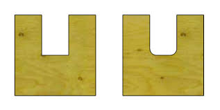
This Picture Belongs to fablabelpaso
Think about if we are going to cut a rectangle in side circle we want .. and Machine like router It is move depending on the line .. It moves depending inside or Outside the Line We draw it ..
So to cut a rectangle inside a circle .. the useless part is the inner part of the rectangle so we cut in the inner .. but if the machine moves in a corner as a 90 Degree it will make it as a circile as the machine wont be able to reach this edge as it is smaller than the bit width ..
This Picture Belongs to FabLab RUC, Roskilde University
so we make at the edge dog bones to with a little bit larger of equal to the bit width to ensure that it will go through it and to can have a good pressfit . .
Q) The process for setting up the router and cutting out your object ?
there are basics processes to use a router ..
1) clean the machine with Plower
2) get the Sheet on the machine
3) Fixed it on the Scrificion Layer with nails
4) Set the Origin and Send GCode to work
Q) How to Select a proper bit with your CNC Router ?
After I made a quite search ..
I found those 2 Links :
Make Magazine
Tinker and Futz
and This is what I learnt :
There are 2 things You need to learn about bits :
1) Types
2) When to use each one and based on what choose
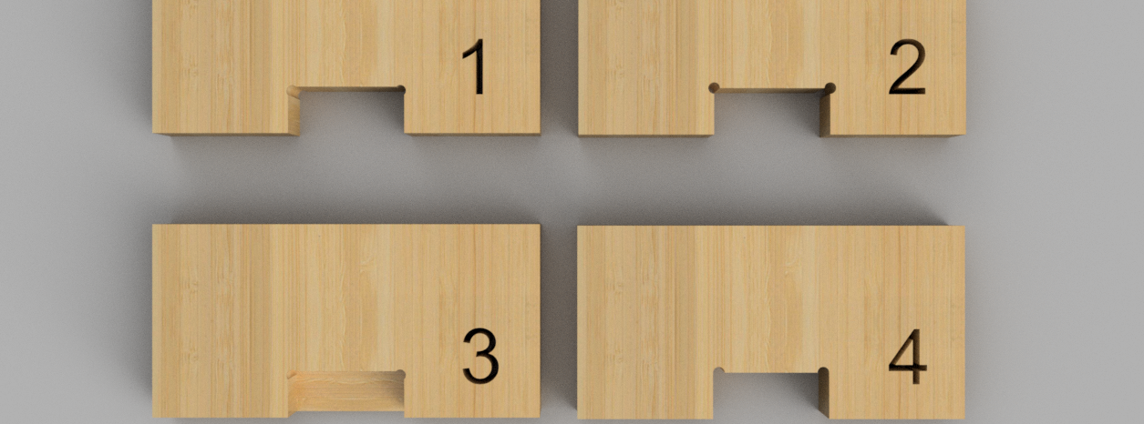
Types of Bits :
There are 6 Bits Essential to know with router :
1) straight flute
2) upcut
3) downcut
4) ballnose
5) V-bit
6) compression and table surfacing bits.
The Bits from left to Right as I said them before ..
Everyone Have usage ..
1) Straight Flute :
These are best for general-use cutting with a good edge quality on many materials.
2) Upcut Endmill :
These spiral, flute-shaped end mills either carry chips up and away from the material or down into them. An upcut will keep the bit cool while quickly evacuating materials when cutting plastic or aluminum, however, it will fray the top surface, and may lift your material so be sure to have adequate hold-downs in place.
3) Downcut Endmill :
Downcut bits ensure a smooth top surface on laminates, assist with holding down your thin parts, and possibly avoiding tabs on larger parts. A single “O” flute is key for plastics like HDPE and acrylic when clearing materials. The flute helps avoid excess heat buildup, which may cause material to stick to and ruin the end mill and your part.
4) Ballnose Mill :
These bits have a rounded tip and are ideal for 3D tool paths. When combined with a “roughing” bit to clear large areas of material, this end mill will result in smooth 3D surfaces, especially with two or more passes.
5) V-bit :
A 60° or 90° V-bit is great for what’s called V-carving, in which the tip of a V-shaped bit is used to cut into narrow spaces, and the wide bottom is used to cut into larger spaces. V-bits can also create sharp corners that other end mills cannot because of their radiuses.
6.1) Compression
These bits combine the benefits of both upcut and downcut end mills, ensuring a smooth top and bottom face when cutting laminates and plywood at full depth passes, considerably reducing cut time.
6.2) Table-Surfacing
These bits are used to surface your table quickly, giving a smooth and level work surface, ensuring accurate cut depths.
Then .. Based on what we start choosing out bit .. As You see each one of the Bits have it is application .. But Beside the Application for each one there are some parameteres we need to consider it when we are going to work with the machine ..
Choose a bit made for your material ..
Hardwood? Plywood? Laminated particle board? Plastics? Aluminum?
Many manufacturers make bits especial for your material of choice. Bits for hardwood are designed to leave a clean edge. Bits for plywood and laminates are designed so they won’t mangle the outer veneer layers. Bits for plastics are designed to avoid excessive melting. Aluminum cutting bits are designed to clear chips efficiently to avoid rewelding (heated chips getting fused to the hot cutting tool). Many bits can be used for multiple applications so you don’t need to buy 30 bits right away if you are in the prototyping stage of your project. A good all purpose bit is a 2-flute up cutting spiral bit.
Use the strongest bit you can
One important thing to remember when choosing a bit is that short, Short bits will produce cleaner cuts. Having excessively long bits invites tool vibration and deflection (bending) of your bit. Both of these conditions make for rough looking cuts and greatly shortened tool life.
Balance your need for speed with edge finish
Generally speaking, the bit design you choose will be designed to cut fast or cut smooth. Think of the difference between a chainsaw (fast) and a hand saw with fine teeth like a fret saw (smooth). If you need to cut a large amount of material in a hurry in a high volume production environment you’ll go for an aggressive bit that can be pushed through your material quickly. If you are making furniture and you’d rather not spend a day sanding a ton of tool marks off your nice hardwood, you’ll want to choose a bit that is made to leave a smooth finish.
The more flutes (cutting edges) that a bit has, the finer the cut. A single flute bit will be very aggressive and leave a rougher edge than a 4 flute bit will. On the other hand, you can push a single flute bit through your material much faster than a 4 flute bit. This is because making one cut per rotation allows for a more aggressive feed speed than a bit that makes 2, 3, or 4 cuts. Chip clearance is also improved with fewer flutes meaning faster cuts.
Choose the appropriate bit direction
Spiral bits are a great multipurpose tool for lots of applications.
The biggest decision you’ll need to make when picking your bit is cut direction. Your choice are uncut, downcut, and compression (a combination of upcut and downcut).
Setting feeds and speeds
Some manufacturers prefer to present a target “chipload”. Chipload refers to the physical size of the chips the bit creates when making a cut. Higher feeedrates produce larger chips. Higher tool rpm produces smaller chips. If your chips are to large, you risk breaking your bit. If your chips are more like a fine powder, you are probably dulling your bit. IT’s a balancing act but start with the manufacturers recommended settings and adjust from there.
Chipload = Feedrate / [RPM x number of flutes]
That is all about Bits ..
:)
Q) What Important Knowledge I need to get out from this assignments ?
1) How to use ARTCAM
2) How to Select my Bit
3) How to Fix my sheet at the machine
4) How to Work with machine
5) How to work with 2D and 3D Design
6) What is Dogbone
7) What is the algorithm used to transform Photos to 3D designs ..