Electronics Production
Task Requirments:
- Characterize the specifications of your PCB production process "Group Assignment"
- Make an in-circuit programmer by milling the PCB (program it, so that you can use it to program your board in Electronics Design week, and in other weeks)
- Optionally, trying other processes.
Milling my in circuit programmer PCB:
End Mills used:
- 1/64 endmill for milling traces
- 1/32 endmill for cutting the board outline
Fab Modules:
First I downloaded the png images of the board from the lecture page.
Milling the traces
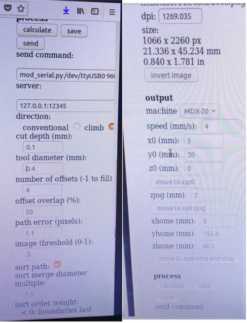
Then I go to Fab modules and upload the traces PNG, choose output format "roland mill .rml", choose process "PCB traces 1/64".
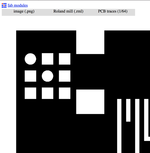
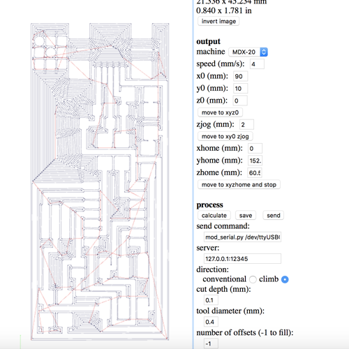
- In the output tab, Choose your machine: MDX 20 in my lab
Adjusting the machine "XYZ zero":
- Fix Your board with a double face tape "in my case it was already fixed from the group assignment"
- Install 1/64 Endmill.
- Adjust XY axis, in my case the x axis was already set to 10 mm and it was ok,for the y axis i had to set it to start after the last PCB was milled by 1 mm so used this simple equation" last position + board width 22mm + 1mm".
- Hit move to XYZ 0
- check your zero
- Fix Your Endmill
- Move Z axis down manually to a close position to the board, then loose the endmill to rest on the board and re fix it, now you have your Z zero position.
- Set the number of offsets, in my case i choose -1 which means the milling machine will remove all the copper just leaving the traces and pads.
- Hit Calculate in the process tab
- Hit send and enjoy the moment !!
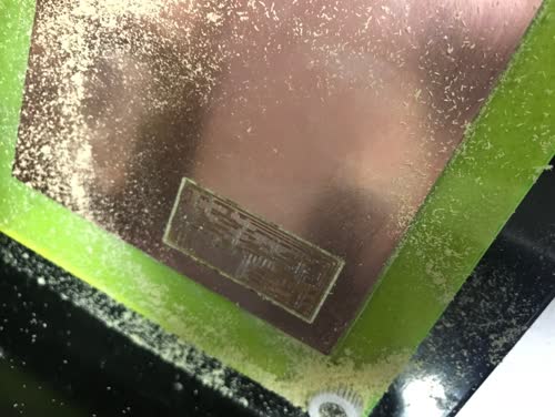
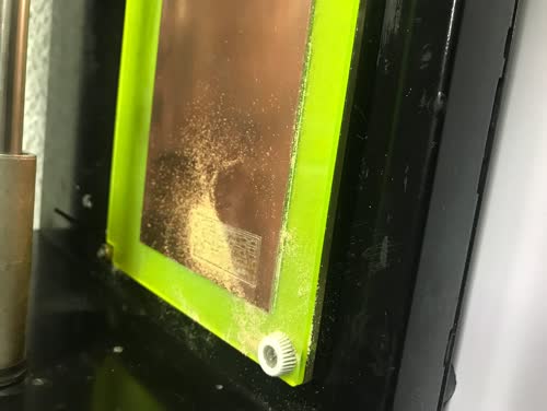
After 18 minutes This is what we have !!
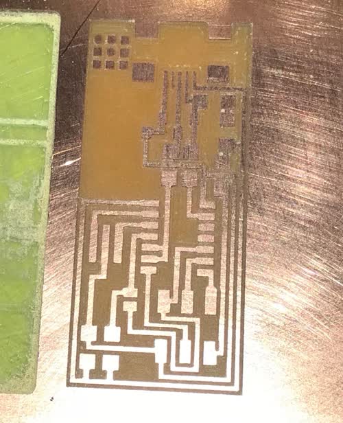
Note: the -1 option gave me a very clean smooth looking board but it took almost triple the time of my collegues.
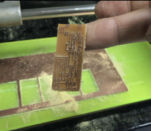
Cutting out the PCB
- import png file "interior.png"
- choose output format "roland mil .rml"
- choose process "PCB outline (1/32)"
- from the side bar choose machine MDX20
- Adjust your zero position to the same values you used for milling the traces.
- calculate tool path
- Install 1/32 Endmill
- Hit run
After 3 minutes
Soldering
Schematic:
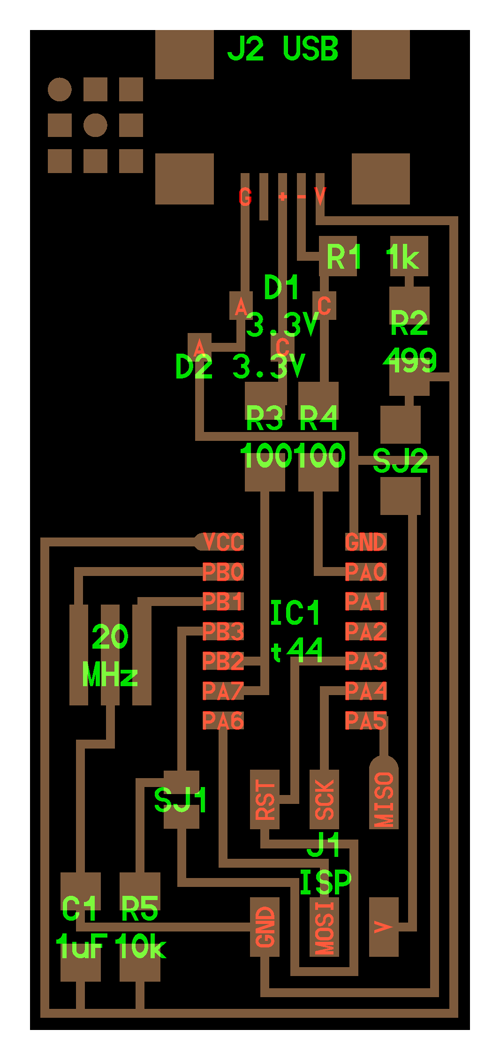
Bill of materials:
- Resistors (1 x 10K Ohm, 2 x 1K Ohm, 2 x 100 Ohm. 1 x 0 Ohm, 1 x 499 Ohm).
- Capacitor 1uf
- Xenor Diode 3.3 V
- Resonator 20MHZ
- USB Connector
- ATiny44 microcontroller
- male 2x3 pin header
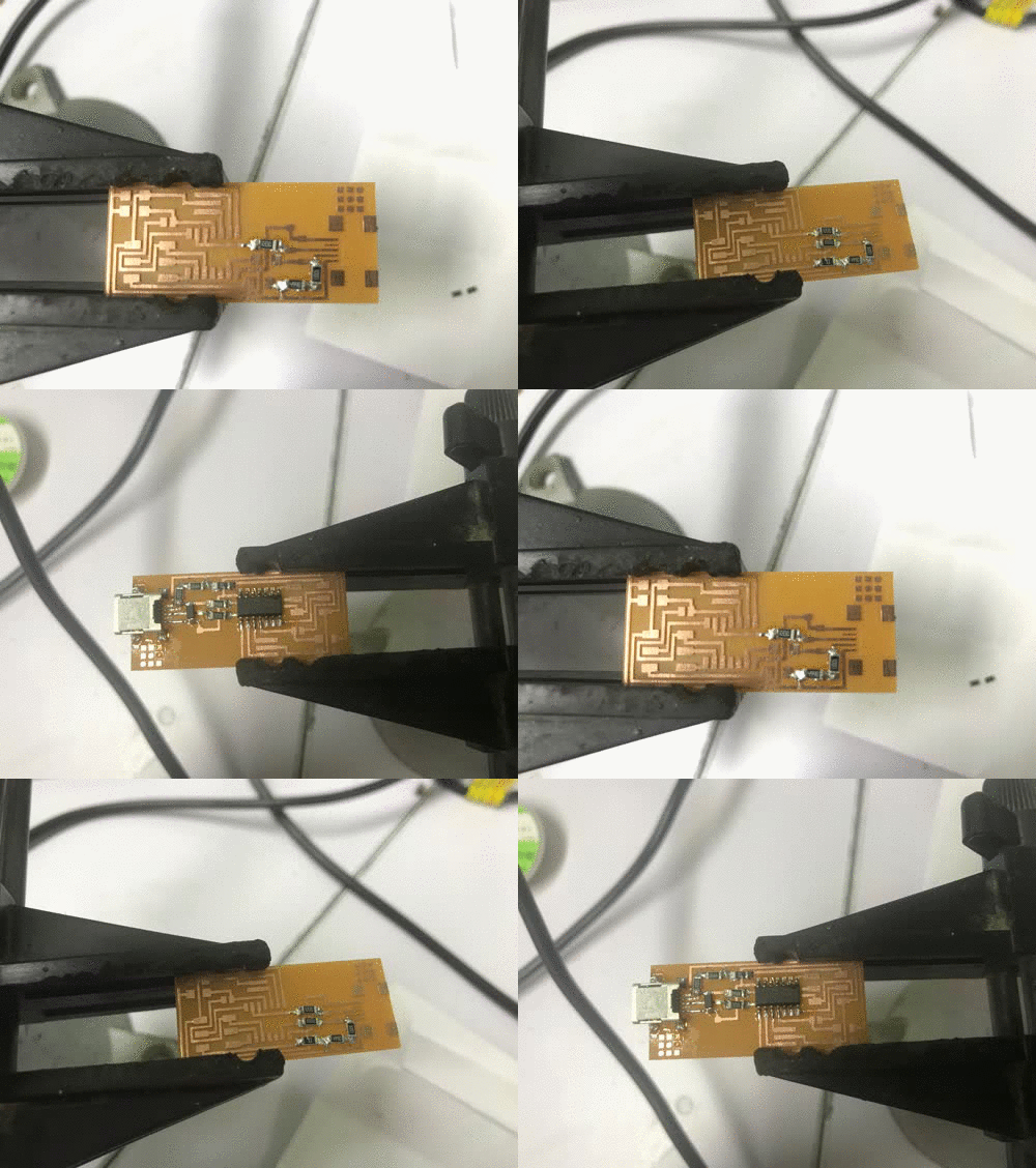
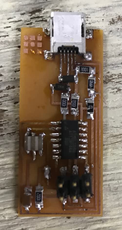
Extra Knowledge
I made the GIF on my mac by following This amazing tutorial which allows me to select the images, right click, make animated GIF.
Programming:
I Downloaded the Firmware from the Lecture page.
I opened the Make file and commented the line for the AVRISP and uncommented the line for USBTINY

In the terminal window i wrote this command to navigate to the firmware folder:
cd desktop/fabISP_mac.0.8.2_firmware
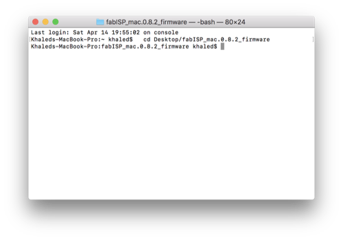
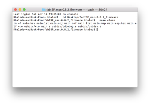
I run the command "make clean"
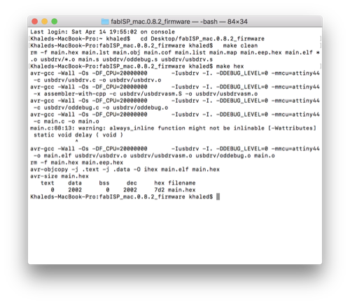
I run the command "make hex"
I run the command "make fuse"
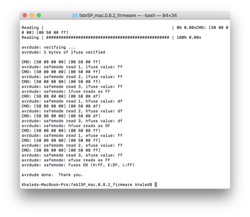
And i received the message avrdude done which is a sign of successful programming
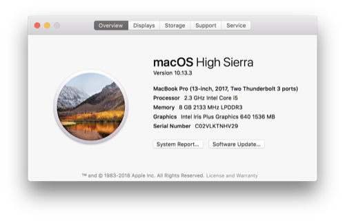
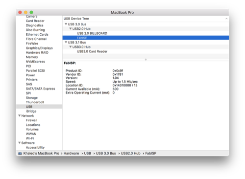
To be sure the board is programmed and detected by the computer, i navigated to about my mac .... system reports .... and under the usb tab i found FAB ISP
Group Assignment:
We use roland modela mdx 20 i the lab to make pcbs.
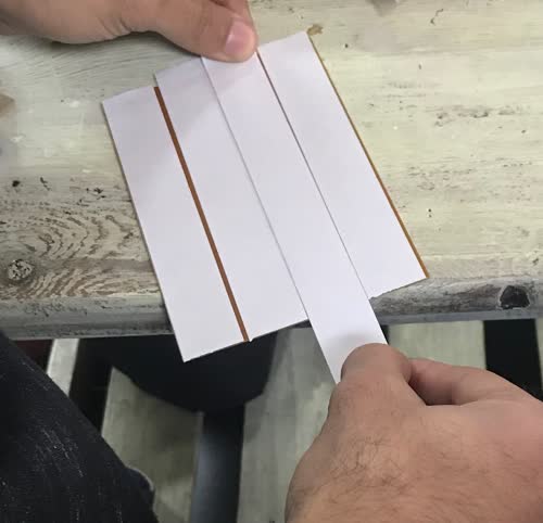
First we put a double side tape on FR1 board to stick it to the table of the modela.
The Fab modules is configured locally on the pc so we had to connect to the machine to get it's local IP
- You Can do ths by doing the following steps:
- open terminal
- type cd fab
- type sudo npm start
- enter admin password
- copy ip adress and port
- in the browser go to the fab modules with the ip and port
Fab Modules:
- import png file
- choose output format "roland mil .rml"
- choose process "pcb traces 1/64"
- from the side bar choose machine MDX20
- Adjust your zero position visually
- calculate tool path
- Enter Your prefered offset number of offsets
- Hit run
And here it is
