Networking and Communications
01
Asignment
Individual Assignment
Design and build a wires &/or wireless network connecting at least two processorsGroup Assignment
Send a message between two projects
Resource
Software
Individual Assignment
02
I decided to make the hello network board for this week, and cut the board.
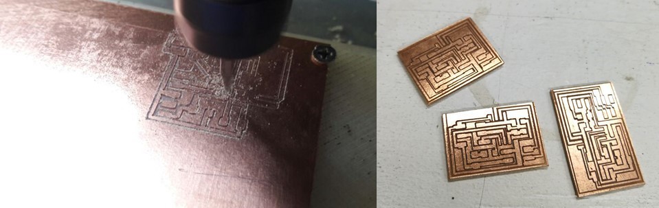
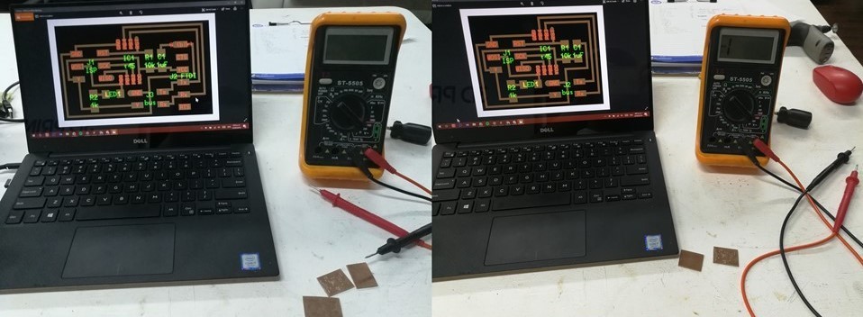
with a multimeter proving that the track has gone well
once welded attiny45 I verify with light.
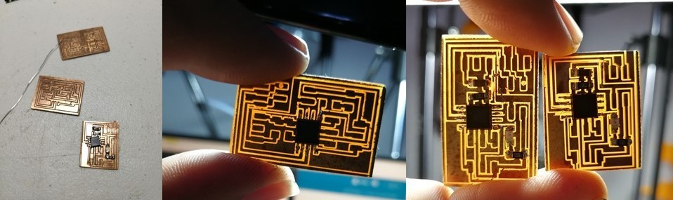
then finish welding the other components.
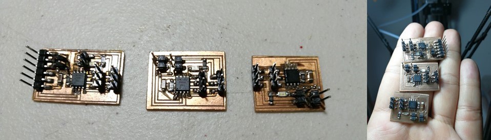
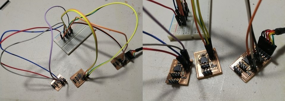
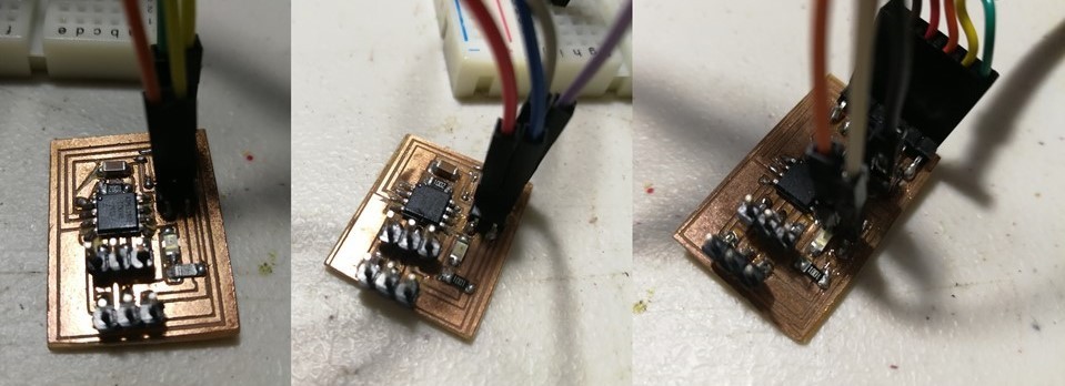
As in the Fablab does not have the connectors for this assignments, I had to use a breadboard and the FTDP cable to be able to program them as indicated in the fab Tutorial.
this is the code to burn the board
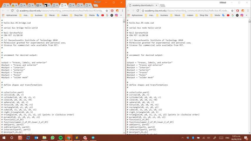
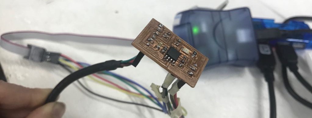
to burn those board i used the AVRMKII and upload the inicial code
then load the code in the Arduino IDE for each board, the bridge literally funsionaria as a node the important thing is to change the value of the files so that you can identify cad one.
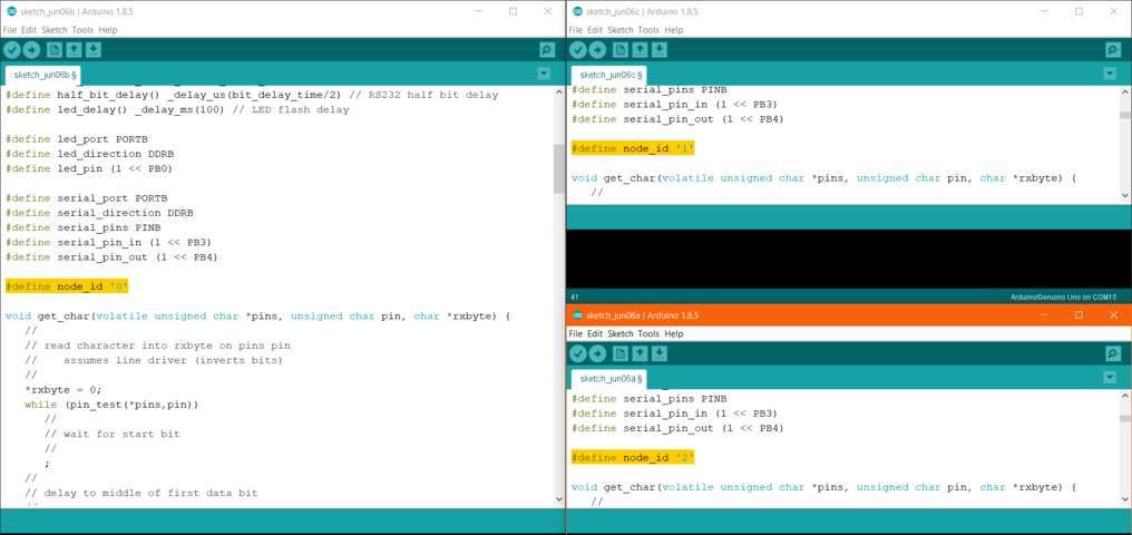
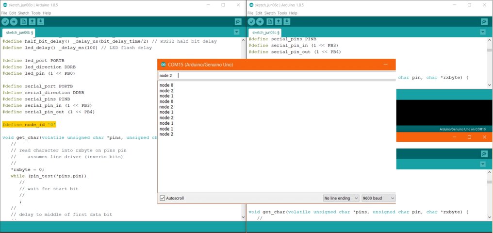
Once the code has been loaded to the boards, we open the serial view to send a command so that the LEDs light up. just write node and the corresponding number of each board will turn on the led asiganacio.
Explanation:
- when uploading the codes for the burning of the board, basically we are giving an identity to the microcochroner that would be the finware of it but identified (bridge and node) which is indicated in which pins will have serial communications (tx, rx). then, using the IDE ARduino, the program will be loaded so that they can do as indicated by their identity.
- The connections of the board indicated by the tutorial is through a special 6-pin adapter, but we do not have one of them in the fablab. I identify what the connections are like and looking for the data sheet of the adapter. Basically it is that all the header pins are connected in parallel but physically it is seen that they are in series but not.
- The microcontrollers communicate through the port tx and rx which is a communication protocol (UART) where tx is the data transmitter and rx is the data receiver.
using the Arduino IDE and through the serial window, I write node 0 or 1 or 2. that data passes through the pins tx of the 3 cards and this card with the same conquede data will use one action (turn on the led).
example: if I send node 2. this information go through the bridge and node 1 but as these two cards do not identify the data according to their orders they will not accept the data if they do not pass it to the next one.
*When the devices are connected in this way, the bridge sends one character using its TX line and the others (node) receives via the RX line and vice versa. to correctly understand how the boards are connected for serious communication in an asynchronous serial manner.Only one device can have control of a UART line at a certain time (bridge). If more than one device transmits to the RX line of another device, an error called "bus contention" occurs. therefore the nodes are waiting for an identified data that is transmitted by the bridge with a low signal or high frequency or data.(he part where they keep their tx-pin as inputs with the pull-up resistor enabled. when they are addressed they change the tx-pin to output and send information, and when they are done they change the tx-pin back to input) thx.
Group Assignement
03
