Programming the board
To program the board I once again used the arduino IDE, so as usual first thing I had to do was to declare my variable.

int an1;    // variable to read the analog va1ue from the analog pin
           int analog1 = 0; //Analog Input
           int pwm1 = 8; //PWM Output
Then in my setup I define the type of my pins:

pinMode(analog1,INPUT);
     pinMode(pwm1, OUTPUT);
This is easy, we read the analog1 pin of the potentiometer so we set it as a input, while we write the result of the analog pin onto the pwm1 pin and send it to our servo so it is an output!
Next the loop, this is where it gets fun:

void loop() {
          an1 = analogRead(analog1);            // reads the an1ue of the potentiometer (an1ue between 0 and 1023)
          int pwmServo = (int)((255.*an1) / 2046.); // convert the analog value to a pwm value
          analogWrite(pwm1, pwmServo); //set pwm
          delay(15);                           // waits for the servo to get there
          }
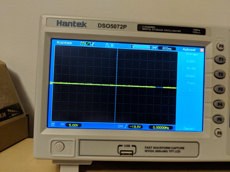
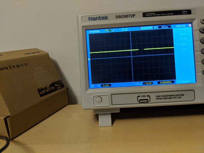
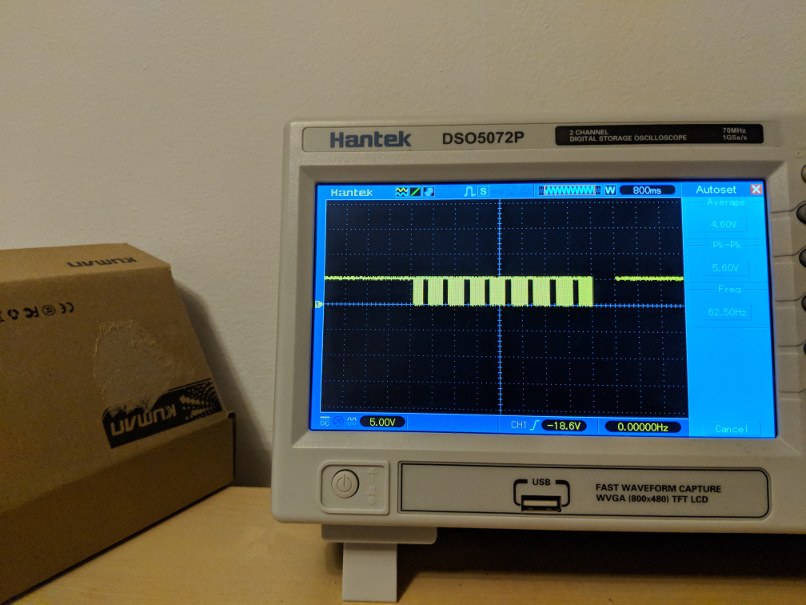
As we know Pulse with Modulation is a digital signal that simulate an analog one, the way it works is that the signal is still digital so it is composed of 1 or 0, HIGH or LOW, This on-off pattern can simulate voltages in between full on (5 Volts) and off (0 Volts) by changing the portion of the time the signal spends on versus the time that the signal spends off. The duration of "on time" is called the pulse width. To get varying analog values, you change, or modulate, that pulse width. Here is an exemple of me reading the pwm signal of my board using an osilloscope:


We can see in the first image that my signal is a 0V this is when my potentiometer is at full capacity, it represent a LOW signal (0 / 255) on the second picture, we see a stable 5v is HIGH (255 / 255), finally we have an image of a square modulation, this is my potentiometer a mid capacity, the signal is converted into HIGH and LOWS and the time between each cycle will set our voltage.
One thing to consider is that an analog signal is set between 0 and 1023 while a PWM signal is set between 0 and 255, thats why I wrote the line
int pwmServo = (int)((255.*an1) / 2046.)
this line take my analog signal, and map it into an pwm treshold.
lets uplaud the code and see if it works!
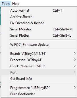
To uplaud the code we do as usual, make sure your programmer is set as usbtiny and that you have selected the correct board.

once the code is uplaud you can test your board!
It works! good job, I had a lot of fun this week, here are
my files!