Soldering the board and Programming the board
I don't have much new to say about my soldering technics, other than the fact that I bought myself an amazing and cheap microscope that serve amazingly to verify my pcb's trace and solder. The microscope can do 10x to 200x zoom and is plug via USB to your phone or compujter and the image quality is amazing, here is an exemple!
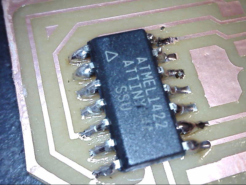
This is a life changer! no more looking half an hour for short circuit!
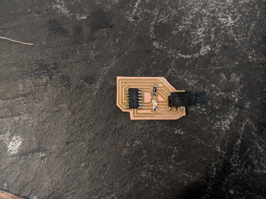
Here is my board, we can now start looking at our code!
Master Code
#include <.SoftwareSerial.h> //
// constants won't change. They're used here to set pin numbers:
const int buttonPin = 3; // the number of the pushbutton pin
const int ledPin = 8;
const int rx = 5;
const int tx = 6;
bool flashing = false;
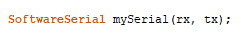
SoftwareSerial mySerial(rx, tx);
// variables will change:
int buttonState = 0; // variable for reading the pushbutton status
void setup() {
mySerial.begin(4800);
// initialize the pushbutton pin as an input:
pinMode(buttonPin, INPUT);
}
void loop() {
// read the state of the pushbutton value:
buttonState = digitalRead(buttonPin);
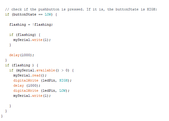
// check if the pushbutton is pressed. If it is, the buttonState is HIGH:
if (buttonState == LOW) {
flashing = !flashing;
if (flashing) {
mySerial.write(1);
}
delay(1000);
}
if (flashing ) {
if (mySerial.available() > 0) {
mySerial.read();
digitalWrite (ledPin, HIGH);
delay (1000);
digitalWrite (ledPin, LOW);
mySerial.write(1);
}
}
}
As usual, we start by importing the library we will need inside our code (In our case SoftwareSerial) and by defining our global variable, for the master, we have the button pin, the led pin, the transmit pin and the receiver pin, these are all integer that will not change during the course of the code, so we set them as
const int (name) = pinNumber
We also need a boolean inside our code, a boolean is a true or false statement. In our case, the boolean will look if the LED is flashing, as a default setup, we set it to false.
bool flashing = false;
Next, we define wich pin will be use for our Software Serial
We will also need to set up a variable that WILL change during the course of the code, the variable will be use to check the button state, if it's HIGH OR LOW.
int buttonState = 0;
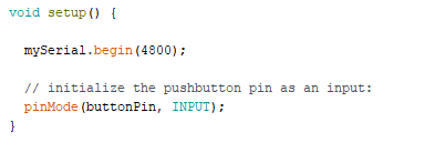
Next thing we need to do is write our setup phase, we really don't need much in this part of the code, we will first start our Serial and then we will initialize the pushbutton as an input, that's all!
Next is the loop:
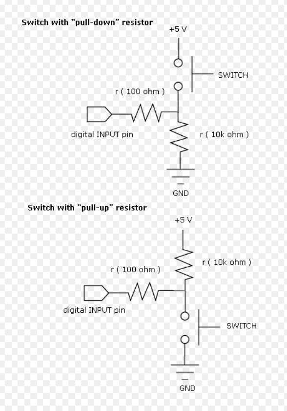
Before I can explain the code to you, I must speak to you about what we call a pull-up and a pull-down resistor. A pull down resistor uses our pushbutton to send 5V to our button pin. With a pull-up resistor our button pin is floating and so goes up to 5V when the pressbutton is pressed, the pin is then link to the ground and the 10K resistor eat all the voltage so we can read 0V to our pin I designed my helloboard using a pull-up resistor that means that in my Code, I will have to use a (LOW STATE) on my button state for me to send 5V to it.
Ok, now let's look at the loop, here we mainly do two things, first we look at our button state, if the button state is LOW (so ON), we invert the flashing variable using this command:
flashing = !flashing;
this tell that if flashing is false, it is now true. And vice-versa.
Next we tell that if flashing is true, (since it's a boolean we don't acutally have to write TRUE OR FALSE, just writing flashing check if the fact is true.) we want to write to serial the value 1.
then we give a delay.
This sent all we need to our slave.
The next part is avout receiving from the slave, we again look at if flashing is true, if it is, we look if my serial is avaible and over 0, if it is over 0, we open our led and we rewrite our serial with a 1.
Slave code
          #include <.SoftwareSerial.h>


const int ledPin = 8; // the pin that the LED is attached to
const int rx = 6;
const int tx = 5;

SoftwareSerial mySerial(rx, tx);

void setup() {
  // initialize serial communication:
  mySerial.begin(4800);
  // initialize the LED pin as an output:
  pinMode(ledPin, OUTPUT);
}

void loop() {
  if (mySerial.available() > 0) {
    mySerial.read ();
     digitalWrite (ledPin, HIGH);
     delay (1000);
     digitalWrite (ledPin, LOW);
     mySerial.write(1);


  }
}
The slave code does basicly the same thing but without the button, we define our pins, initialize our SerialSoftware, set our LED as an output, read our serial, check if the value coming from it is over 0 and write 1 to our serial so the LED of the master can open. EASY PEASY!
You can find my files
here!