Soldering the board and Programming the board
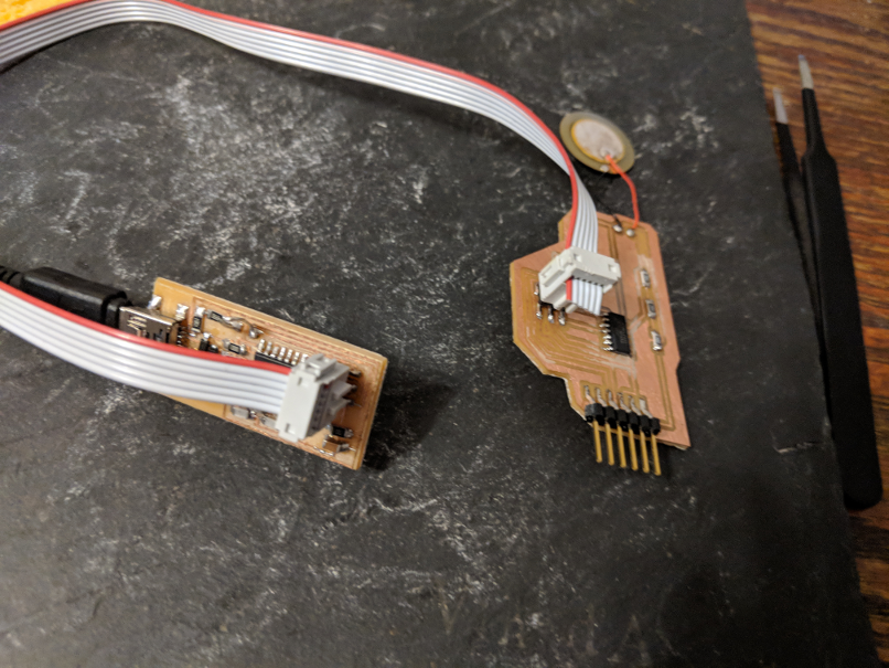
Im used to solder SMD components now, it is like a reflex, and like they say pratice makes perfect! Always be sure to be in a safe and secure environment, be relax and patient. Here is the board once everything as been done:
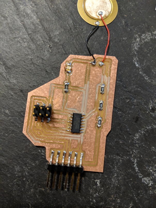
now that our solder are done, we are ready to program and test our board. My program is heavily influenced on the Knock Arduino exemple, it is a simple code that I modify to have a more sensible piezo and I import the Software serial library instead of the serial lbr since the attiny only runs the softwareserial. here is the final code:
        #include <.SoftwareSerial.h>


SoftwareSerial mySerial(5, 6); // RX, TX

const int ledPin = 10;      // LED connected to digital pin 10
const int knockSensor = A0; // the piezo is connected to analog pin 0
const int threshold = 20;  // threshold value to decide when the detected sound is a knock or not


// these variables will change:
int sensorReading = 0;      // variable to store the value read from the sensor pin
int ledState = LOW;         // variable used to store the last LED status, to toggle the light

void setup() {
  pinMode(ledPin, OUTPUT); // declare the ledPin as as OUTPUT
  mySerial.begin(9600);       // use the serial port
}

void loop() {
  // read the sensor and store it in the variable sensorReading:
  sensorReading = analogRead(knockSensor);

  // if the sensor reading is greater than the threshold:
  if (sensorReading >= threshold) {
    // toggle the status of the ledPin:
    ledState = !ledState;
    // update the LED pin itself:
    digitalWrite(ledPin, ledState);
    // send the string "Knock!" back to the computer, followed by newline
    mySerial.println("Knock Knock FabAcademy!!!");
  }
  delay(100);  // delay to avoid overloading the serial port buffer
}
First of all we know since the beginning of our programming course that the attiny does not share the same pin number as our arduino uno, just as a reminder, here is the comparison chart for the attiny45 and 44:
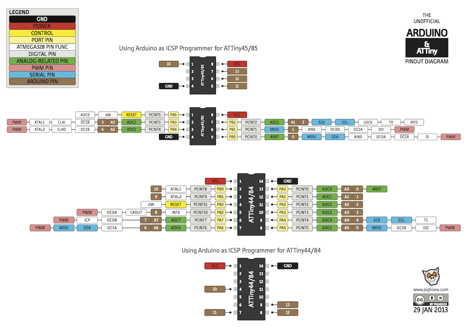
Ok let's look at the code step by step, first we need to insert and set our SoftwareSerial library, we will set our RX pin as our pin number 5 and our TX pis as our pin number 6.

then we declare our variable, first, we set our led pin as the pin number 10 and the piezo on our pin analog 0. Also, we need to set our treshold in wich the piezo will send a signal.

Then we can set the variable that will change during the lecture of the code, first the variable that will store the value of our piezo and also the variable that sets the state of our LED.

In our setup, we will set ou LED as an output and we will begin our Serial.

The rest of the code is our loop, it does multiple thing, it change the value of our sensorReading variable depending on the analog read of our piezo analog pin we also change our led status each time our sensorReading has a bigger value than our treshold and we print to our serial a text.
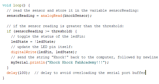
This is it, let's uplaud the code using our fabISP and see if it works!
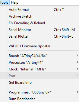
It's not perfect but it works!! Here are
my Files