FINAL PROJECT
INITIAL IDEAS
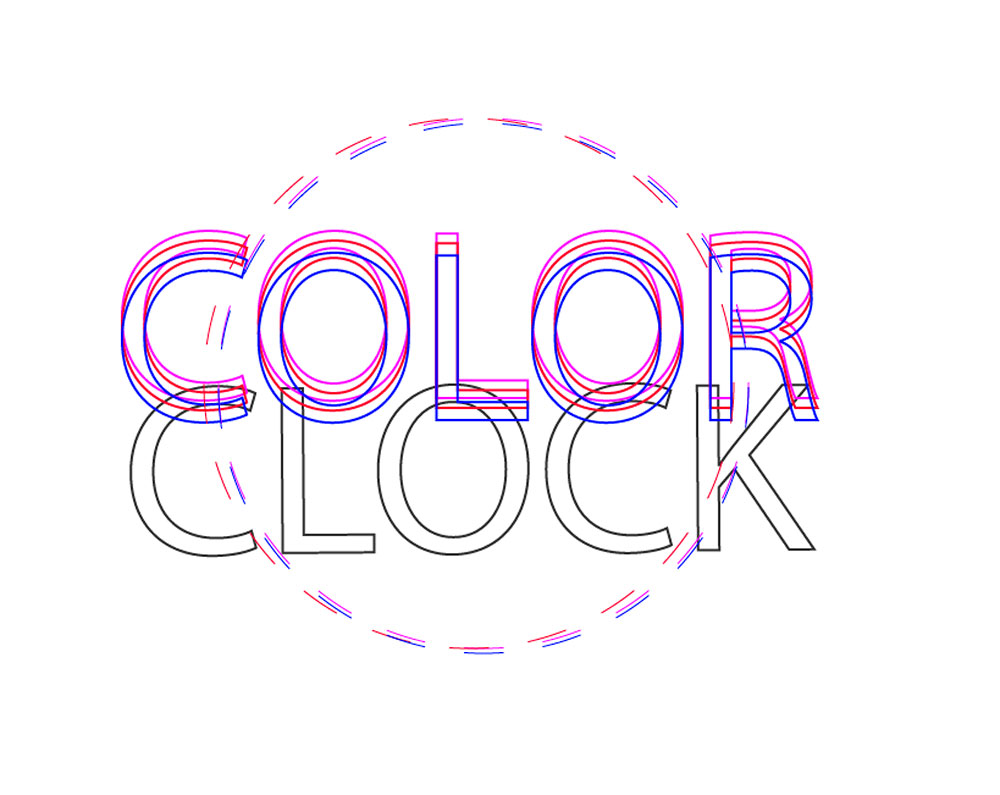
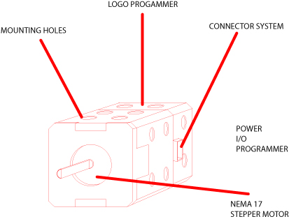
The initial idea for my final project was to make a set of ATtiny based boards capable of running microLogo, created by Brian Silverman, it is a version of the Logo programming environment. These boards could then be used to operate motors and LED's. This project relates to an ongoing interest I have in exploring Logo as an alternative to Arduino for larger scale installations or making technical objects where inputs and outputs can be networked together. I was initially thinking of working with motors to make some kind of animation machine as was described in Week 1.
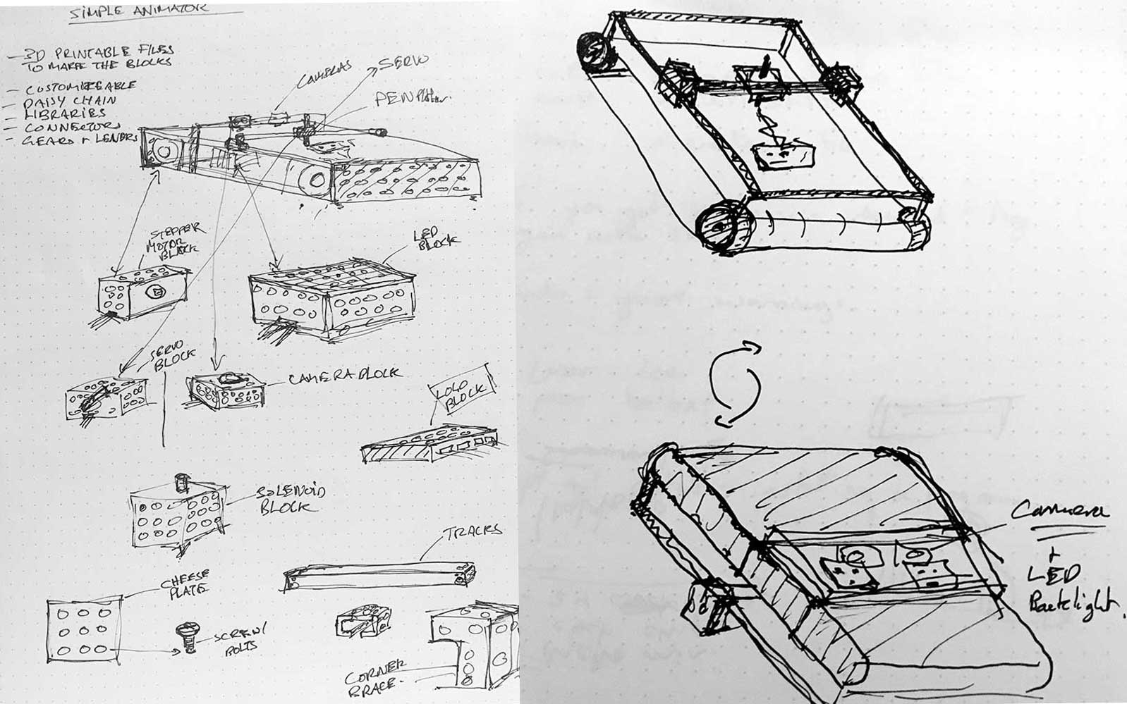
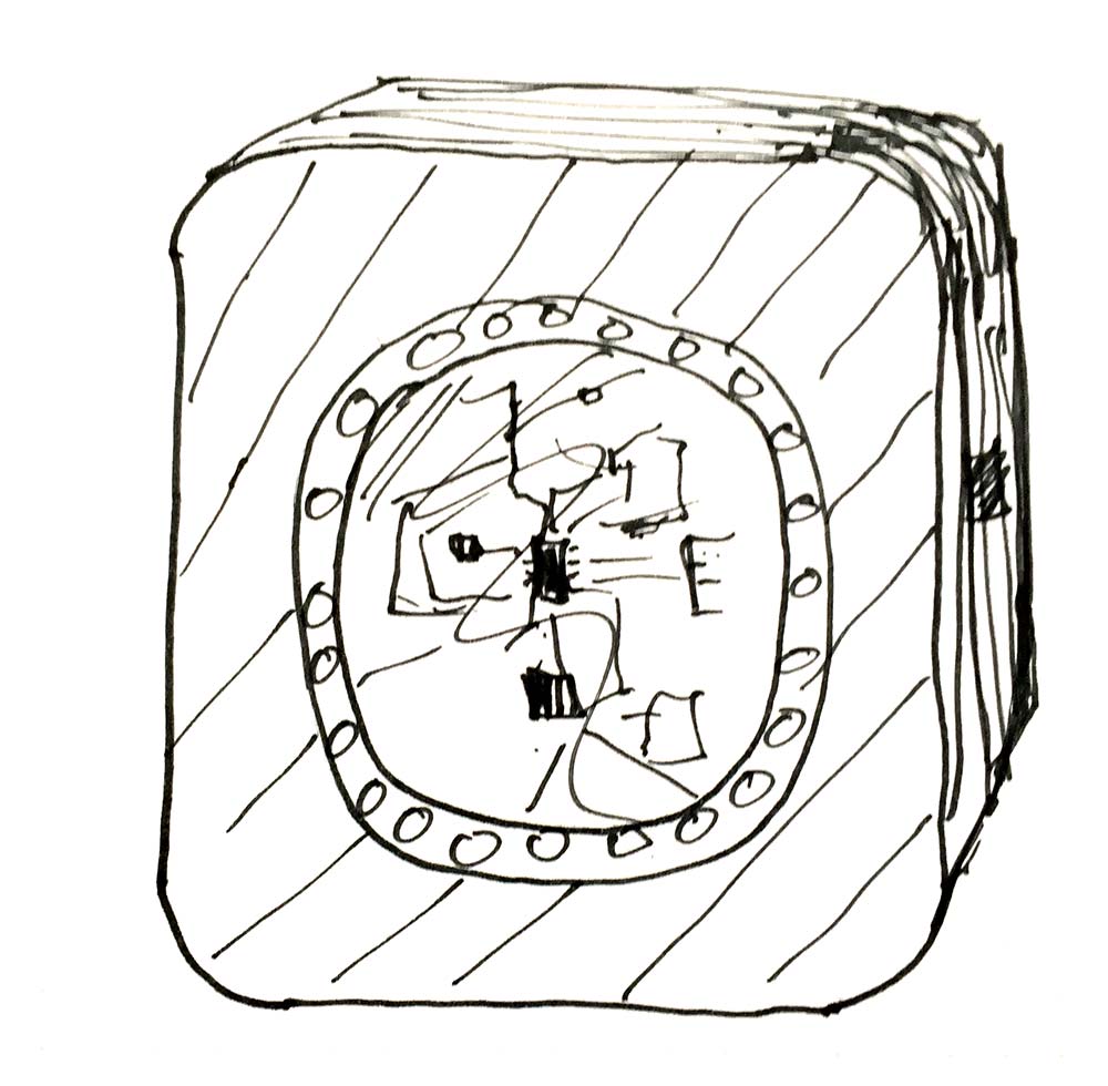
The following sketches were designed in Inkscape during the Week 3 - Computer Aided Designassignment.
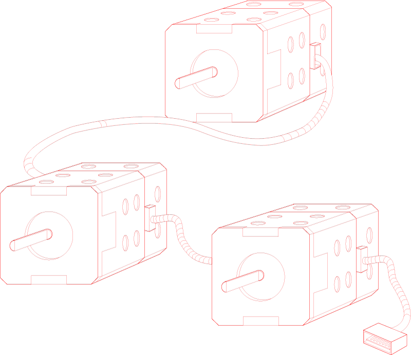
After some discussions with my fellow peers and because I had already been working with Logo to control Neopixels, I decided it would be better to start working with light. My final project idea started shifting towards making a scalable LED matrix. The following renderings were also created in the computer aided design assignment using a combination of Fusion 360, OpenScad, and Illustrator.
This route would require a lot of time developing the right connector system and effective power distribution, as well as building a proper framework for networking devices. It became apparent to me that the scope of this approach would have been challenging considering the skills I would need to learn leading into it and the time I had. In the end, and largely due to Brian's availability to help me learn how to work with microLogo, I settled on the idea of making a version of the Color Clock. It is a good Fab Academy project and it fits nicely with my interest in using Logo to make a technical object. For more information on the Color Clock concept visit my Applications / Implications assignment on Week 18.
As I mention in Week 18, the goal of this project is to make an object that demonstrates time well spent in a Fab Lab. An artifact that was made using many processes from Fab Academy assignments so that when you look at it you are reminded of the time spent learning new processes. At the core of this project, is a custom circuit. Because embedded programming and electronics is a recurring theme in the Fab Academy, it seems appropriate to me that it be central in this design. I also really like the look of a milled circuit and I wanted to highlight this.
PRESS-FIT CONSTRUCTION
After the Computer Controlled Machining assignmnent on Week 4 I was very interested in pursuing press-fit construction to make different objects. I used press-fit for the Computer Controlled Machining assignment on Week 8 and I decided to use it again for the Color Clock. I wanted to make an interesting looking object that did not require any glue or fasteners.
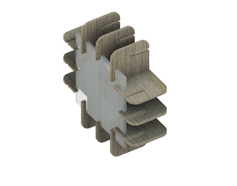
This early model was created as a way of suspending the NeoPixel ring and circuit holder within a structure.
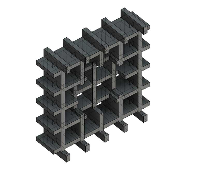
To make it possible to fit the holder into the press-fit structure, I measured three spots on the ring where the slice could press against the holder to keep it in place.
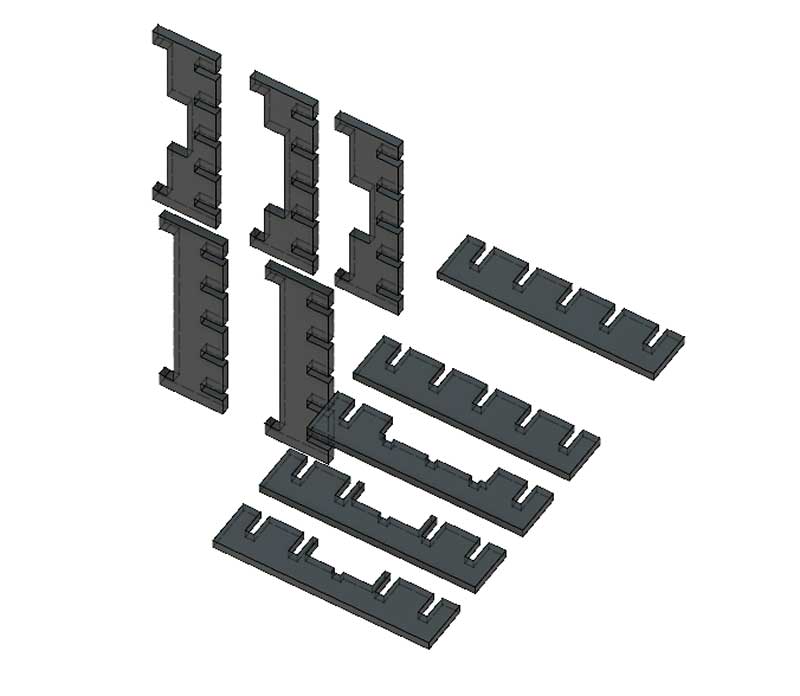
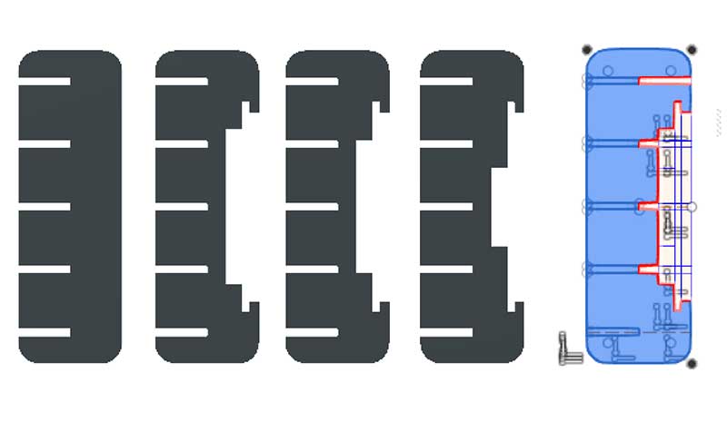
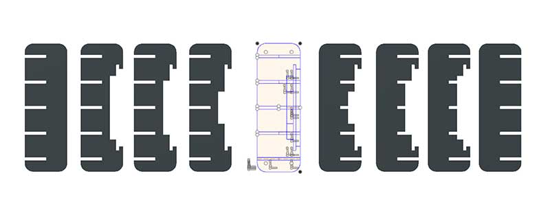
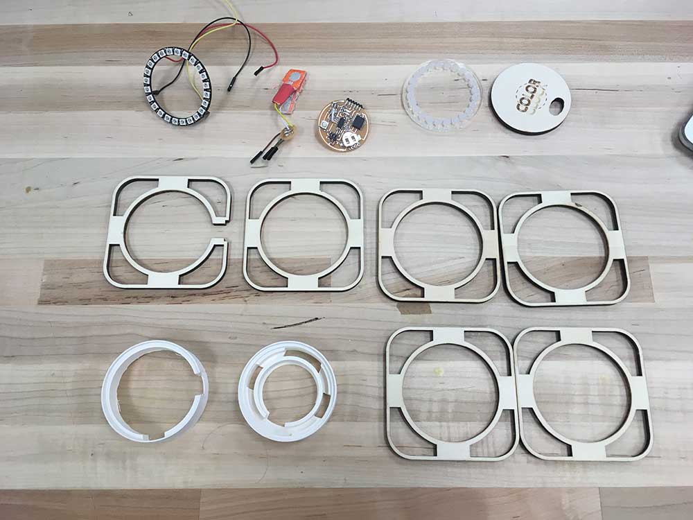
In the end it would take about 10 slices to make this version. I tried to re-design the object to look a little less heavy. I used one sketch to generate the different parts. I just had to select which elements I needed to extrude in order to create enough parts to press-fit around the Neopixel / circuit holder.
From this one sketch, I was able to to generate all the parts I needed to make the press-fit body.
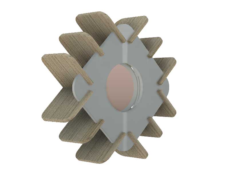
I really liked the idea of press-fitting a piece of glass with diffusion in front of the Neopixel ring. AS if these electronic elements were frozen into the shape. I made a couple renderings to visualize what this might look like. I had two ideas in mind, one was a piece of transparent glass with some kind of diffusion in front of the pixels. The other was a piece of frosted acrylic with a hole in the center to expose the circuit.
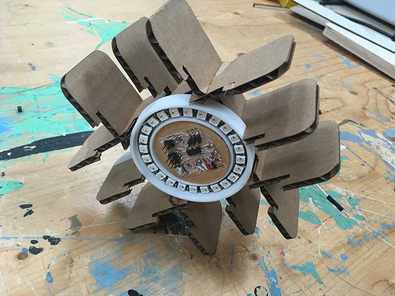
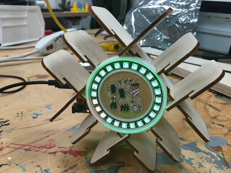
I cut the parts out of cardboard to test the design. It worked nicely in the sense that I was able to press-fit the holder into the structure which is what I was hoping. I made another test with plywood to test the strength. I hadn't quite figured out how to get the Acrylic in. I needed to remove some of the slots so it would fit in. I really did not like the look of this design so I abandoned it in favor of a simpler look.
---> Final Design
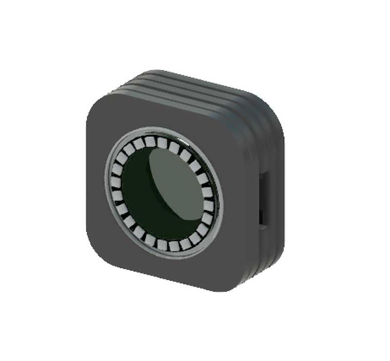
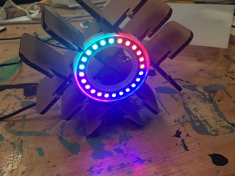
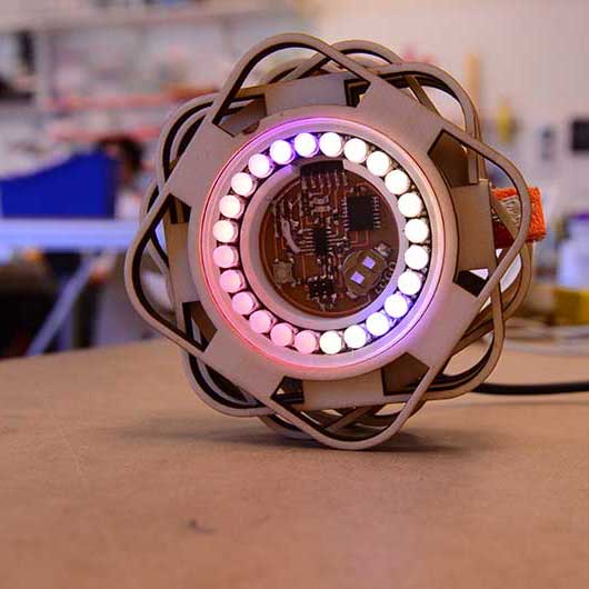
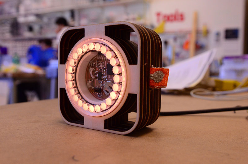
For my final project I reverted to an early sketch. I decided to make something the size of a bedside alarm clock. I was concerned with two things regarding the design. One, making something more interesting than a cube. Two, doing something nice with the light that the clock emmits without it looking too much like Iron Man's heart.
My first model looked closely like my sketch but was a bit to un-interesting. It didn't really demonstrate the uniqueness of digital fabrication.
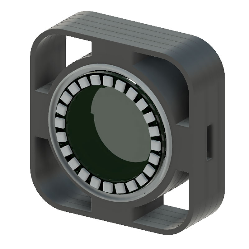
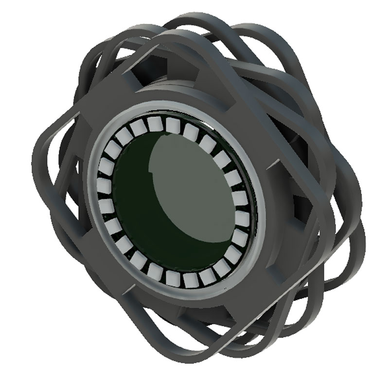
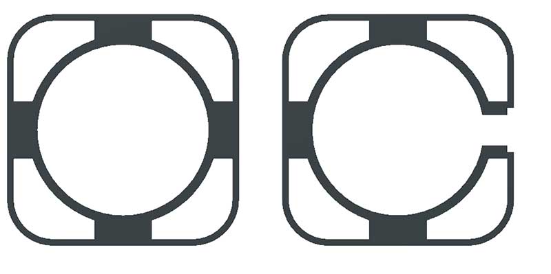
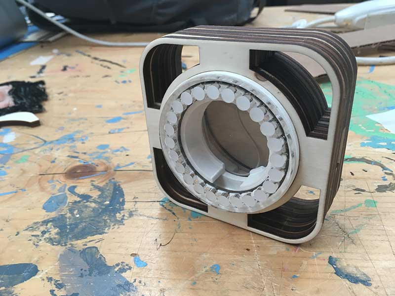
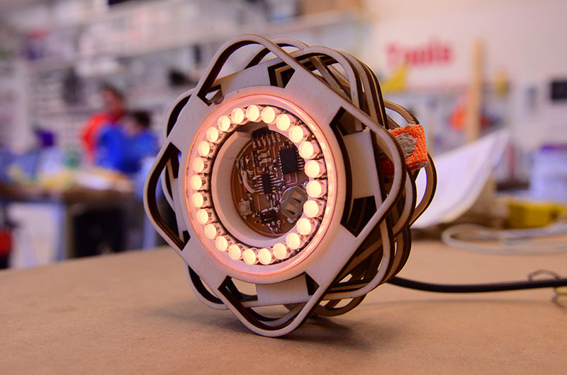
I decided to carve out the corners of the shape to make to make it more appealing. This really helped to lighten the design up. I was even more interested in the fact that if I twisted any of the slices then the shape of the clock could be manipulated. This really helped to emphasize a nice character. It made the object more playful, customizeable, more digital. All of which summarize the relationship I have with Logo and digital fabrication.
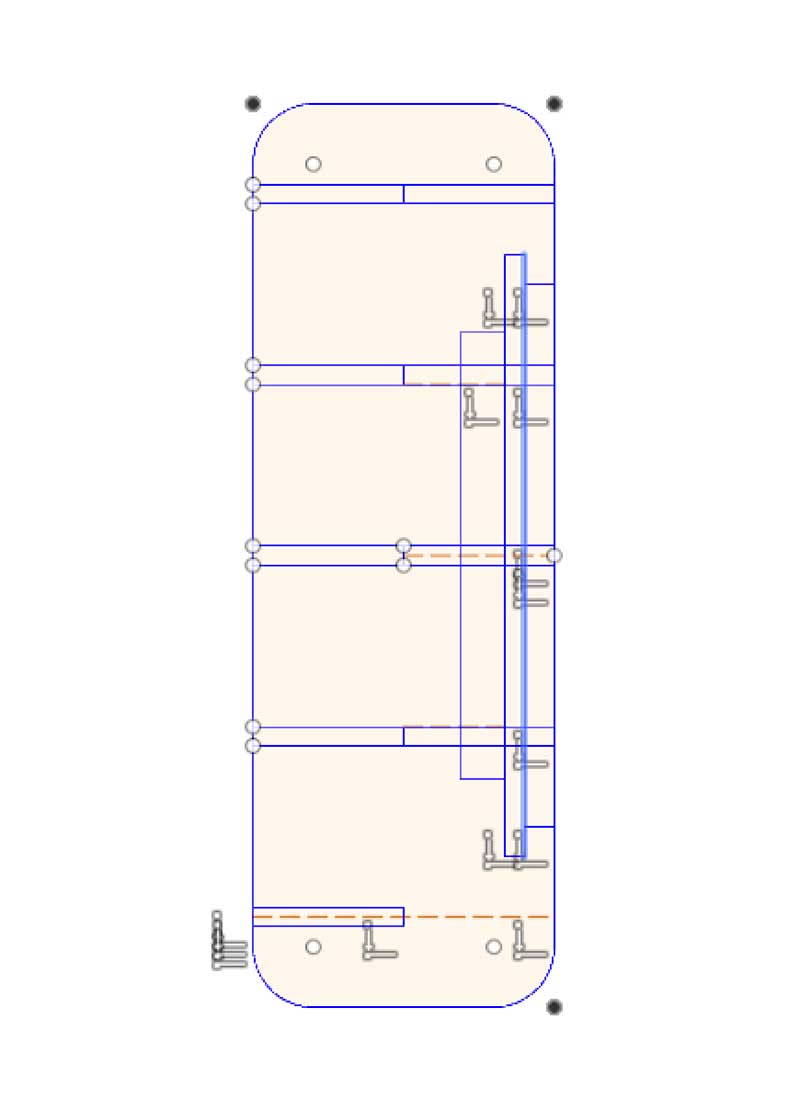
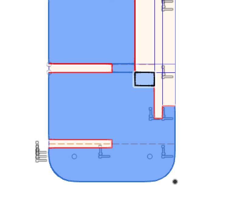
The entire frame of this clock is made with one sketch. There is just one slice with a gap in it. This is where the soft button is supposed to go. As I did in my previous iteration, I only extruded the portions that I needed.
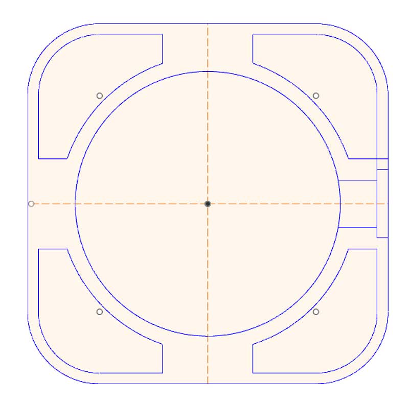
The body of this clock works by press fitting the pieces around a 3d printed core which is the holder for the circuit and the Neopixel.
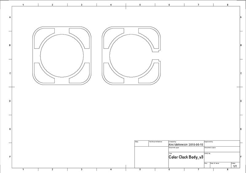
To transfer the 3d model into cut files. I created a drawing from the model and exported a PDF which could then be sent to a laser cutter. Making sure that the ratio was 1:1. This process is the same that was used in week 8.
---> making the core
The core of the clock body took a few tries to figure out. Many were done during the Molding and Casting assignment on week 10. Features for this design include:
---> a channel for wires
---> nested ledge to hold the Neopixel
---> a hole in the side for the soft button
---> a notch for the FTDI connections
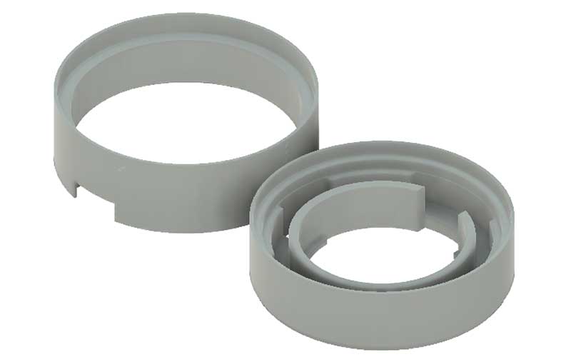
The core of the body is printed using a white PLA. The print took about $50 minutes per side using the low quality setting. What is nice is that this matte white filament looks quite good at the low settings. The visible layering actually gave a nice texture on such simple geometery.
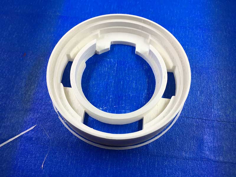
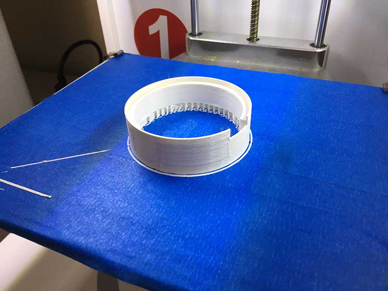
The shape did not need to be printed in 2 parts but I did it this way thinking it would make it easier to have access to the wires in the back of the clock. The purpose of the back piece is really to provide a chamber for the wires and and button circuitry.
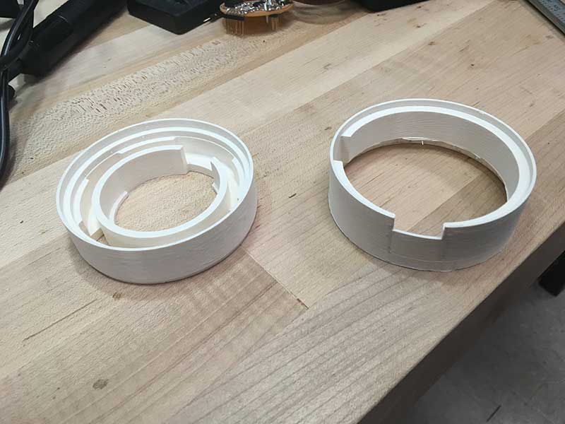
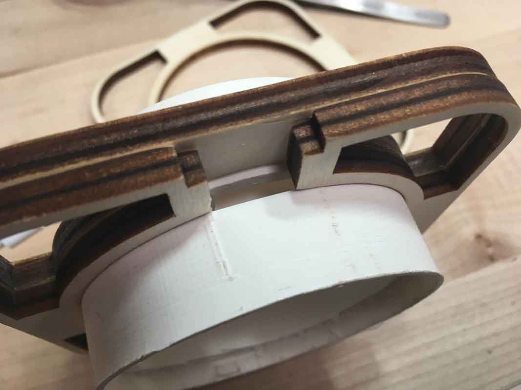
The two pieces also snap together in a press-fit manner. The depth of the core is enough to give the right thickness which equates to 7 pieces of 6mm plywood.
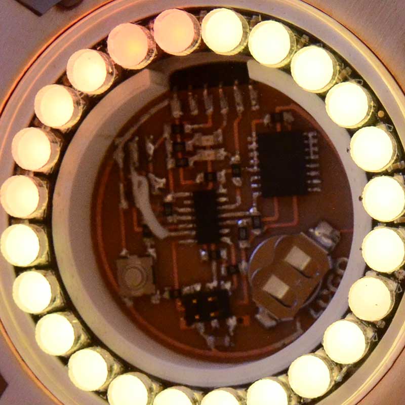
LED DIFFUSION
One of the main visual features of the clock is the LED diffusion. I really dislike the look of the bare LED's and wanted to find a classy way to diffuse the light which can be harsh.
I had a piece of white Trotec Troglass LED matt white acrylic that is meant for light diffusion. The challenge was to keep the colors of the LEDs from bleeding into each other. Using a large sheet would clearly not work. I could divide larger sections of color but with the color clock I needed to be able to have more definition so that the individual dots could be seen.
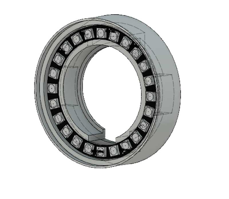
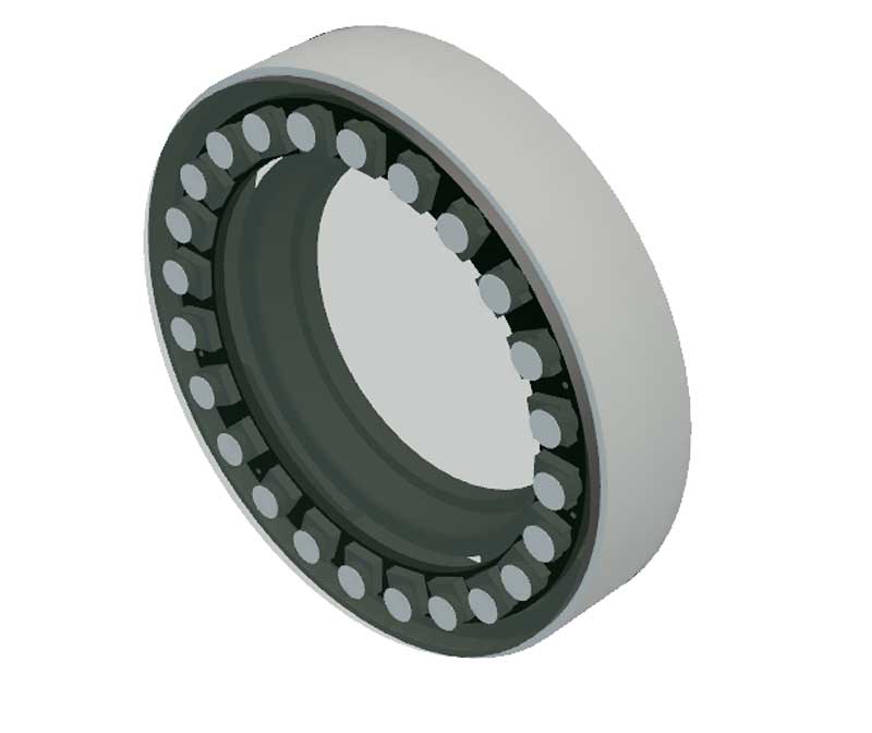
I decided that it could be both visually appealing and effective to put diffusion in front of the different pixels separated by clear acrylic. The color from the light could essentially escape through the clear acrylic except in the specific areas where there are dots of diffusion. Here is a 3d rendering I made to illustrate this.
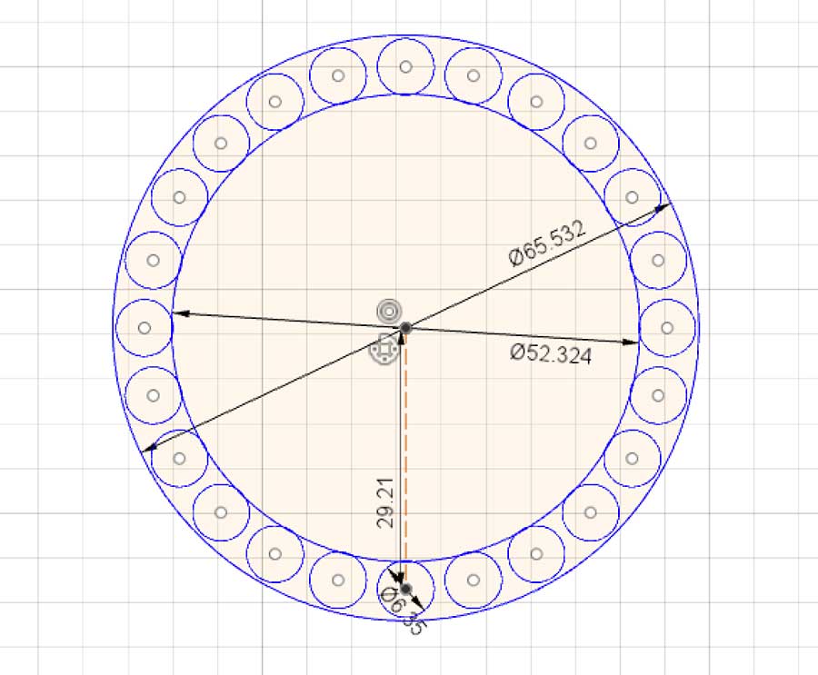
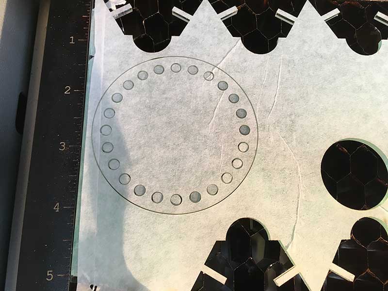
I took all the measurements from the schematics for the Neopixel ring on the Adafruit page HERE. I then used the circular pattern tool to create a pattern of 24 circles around the ring. The size of the circle was just big enough to hide the white square body of the actual LED. This worked out pretty well.
I did several tests to check the size and spacing of the dots and I tried a few techniques for diffusion.
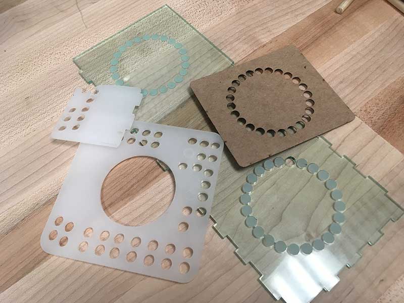
I first tried engraving the dots on the Acrylic directly. This worked out well but you could actually see the texture from the markings. I also wanted find a more creative way to achieve this. I also tried press-fitting the dots into the acrylic. I did a quick test in front of an LED and found it to look very nice. The dots look more even and diffused.
Engraved dots.
Press-fit dots.
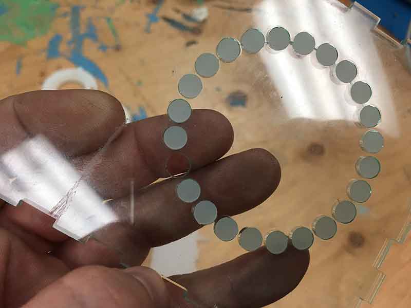
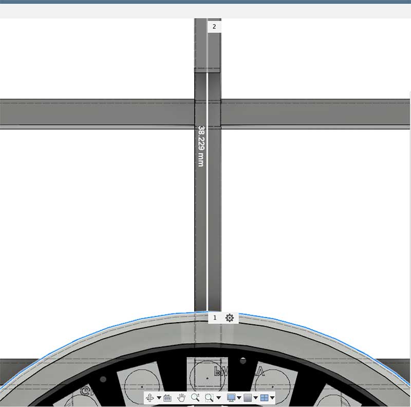
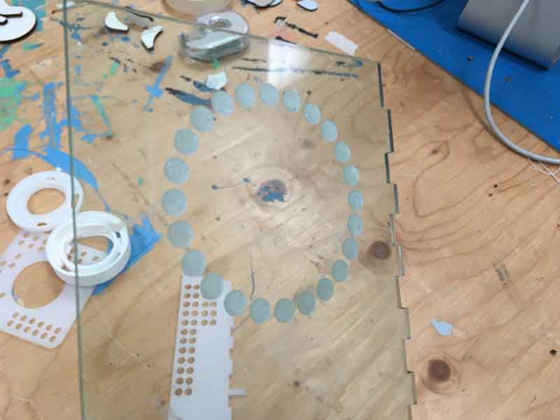
Getting the right dots to effectively press-fit into the material took several tests. The size of the sketch for each dot is 6.35 mm and the right size to cut was 6.55 mm. This means that the kerf of the laser was around .2 mm
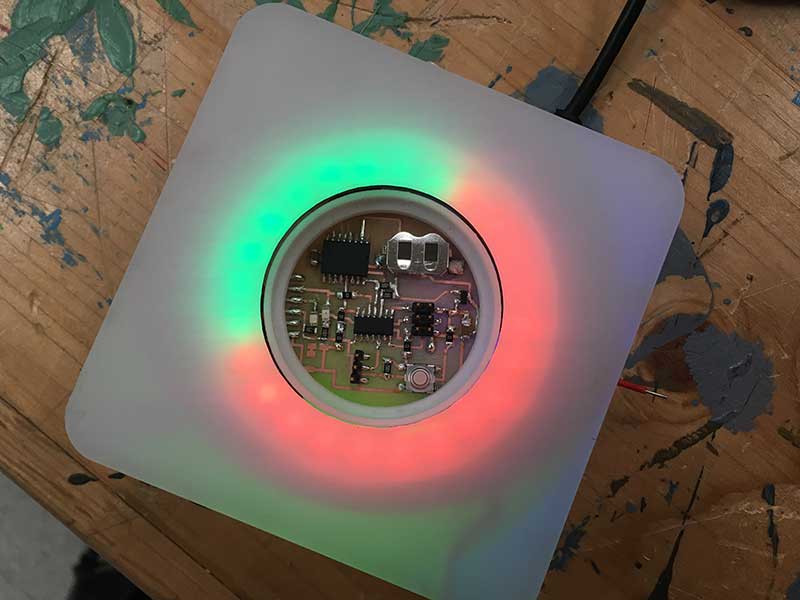
The final version of the diffusion screen was done with 6mm clear Acrylicof. This gave a nice effect of the glass protruding a bit from the body of the clock.
This also made for some nice visual effects with the liht refracting off the clear acrylic.
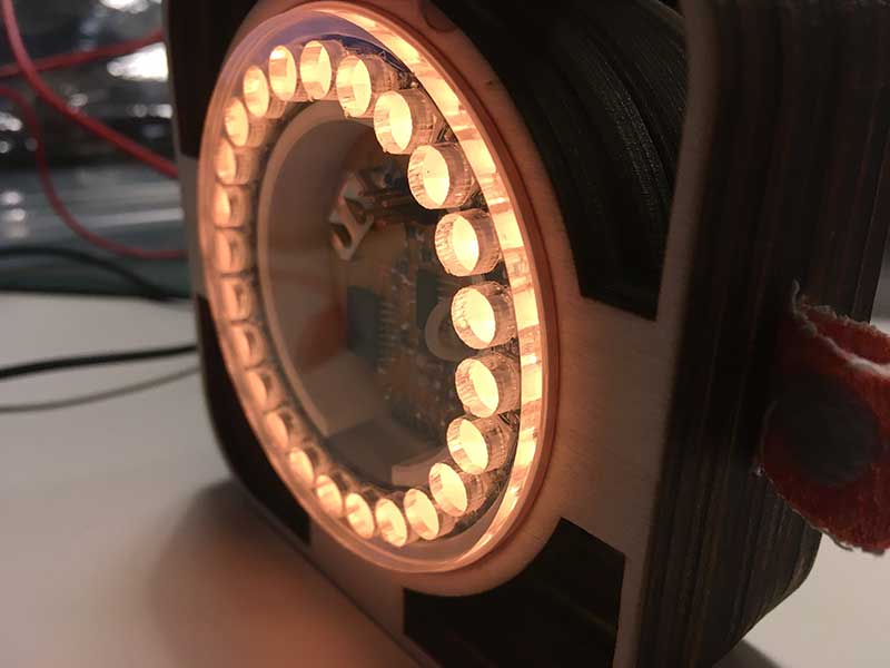
The design of the LED diffusion was a big success for me. I really like the effect it makes. Each LED can be colored differently without it spilling over.
PRESET BUTTON
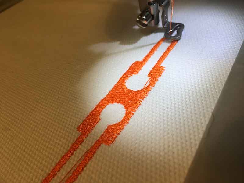
I wanted to make a preset button on the color clock so that I could toggle between settings. One setting would be Brian's original color clock code, and the other would be my own version. It is also a nice feature to play with once you start coding with Logo. I decided it would also be fun to make the button out of textile and conductive thread. There is also an advantage to this. The action of squeezing a tab is less likely to push the clock around whereas hard button on the body of the clock would require a gentle touch for such a light object. The soft circuit button was made with conductive and orange embroidery thread. To see the initial tests with conductive thread and the process of working with an embroidery machine, visit my assignment during Wildcard Week.
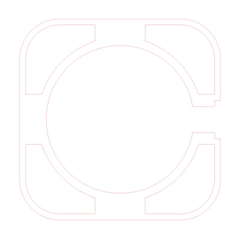
The initial vector drawing for the button was a two color image. The grey sections are conductive thread and the orange is just decorative. The embroiderer sees this as two separate thread types and pauses the job so you can change the thread in the machine. A very simple process.

The embroidery machine started first by laying out the orange thread. It starts off with the cross stitch and then continues to embroider the thread at a 90º as I had selected in the Sewart software.
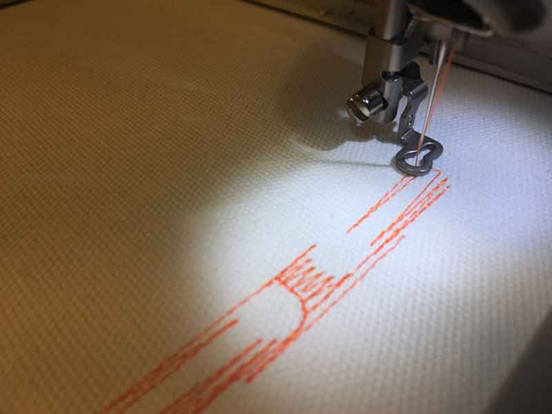
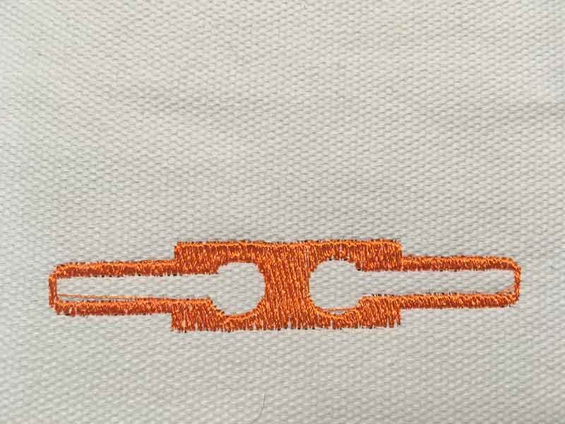
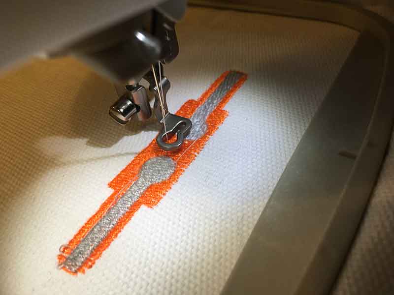
The final look of the orange embroidery was nice and clean. Once it was completed the machine paused and I swicthed the embroidery thread and the bobbin thread from regular to conductive thread. I was a bit worried about removing the embroidery loop in order to change the bobbin thread underneath. It is not the most gentel process and I did not want to somehow miss-align the needle.
I was happy to see the embroidery machine return to the exact spot where it left off. This was my first attempt at using two colors and it went smoothly.
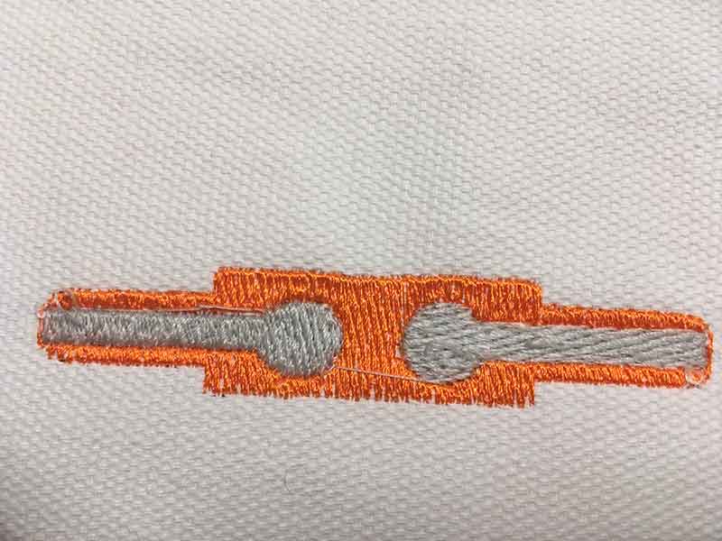
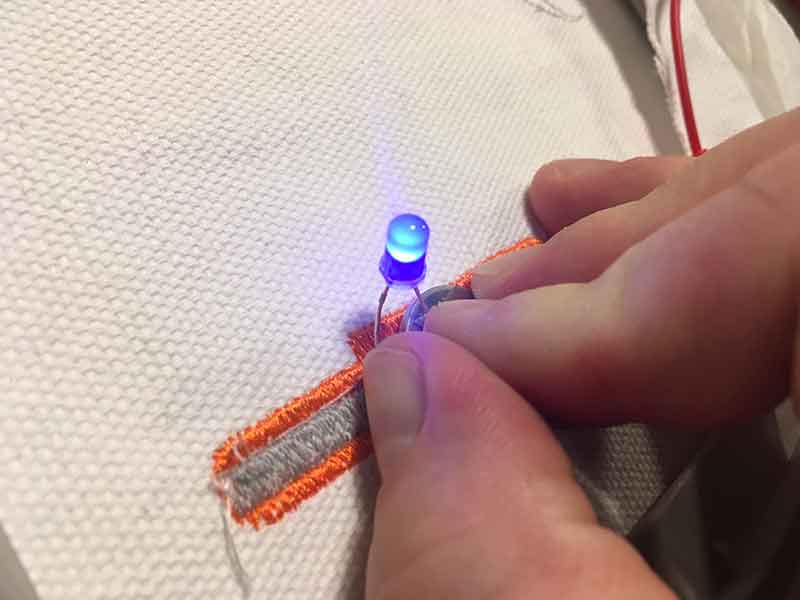
When the job was done, I did a conductivity test with a coin cell battery and a blue LED to make sure enough electricity could pass to operate the button. I was also pleased to see this work out.
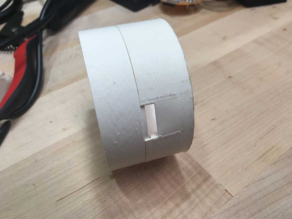
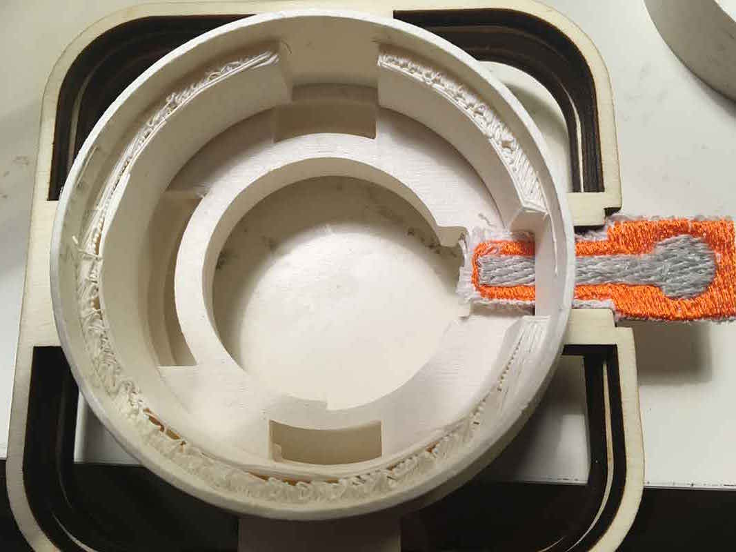
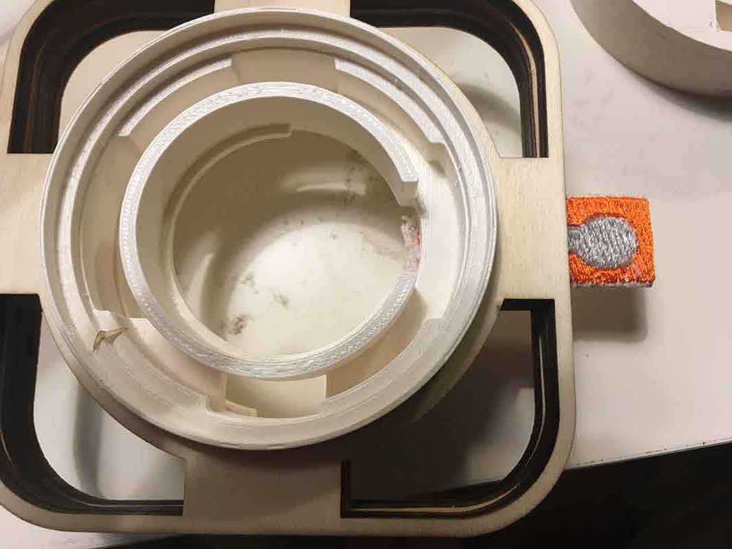
The 3d printed core of the the clock had a notch cut out wich is meant to line up with the wooden slice with the notch in it.
I still needed to make the button electronics but wanted to first test the fitting of the button into the frame and core of the clock.
---> making the button electronics
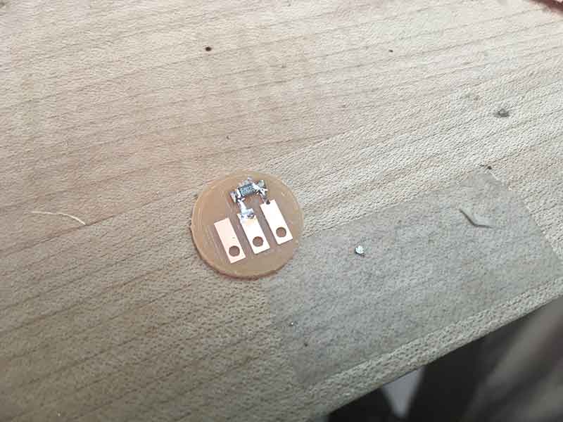
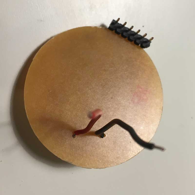
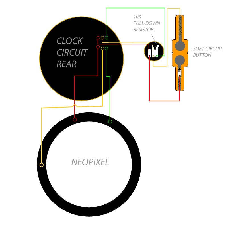
Now that the button was made, I needed to attach it to the rest of the clock. Before I could do that, I needed to make a pull-down resistor and find ways to make an adaptor from conductive thread into hook-up wire. I quickly milled a little circuit and added a 10k resistor to bridge between ground and one end of the button.
I made another little copper part which I could solder hookup wire to and also sew conductive thread.
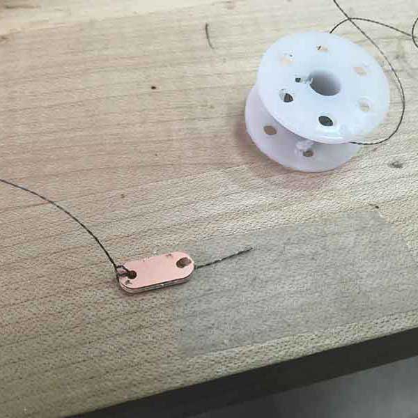
I wrapped a few strands of conductive thread around the little adaptor. I am not sure if it was necessary but I really wanted a solid connection to avoid opportunities for noise to enter the signal.
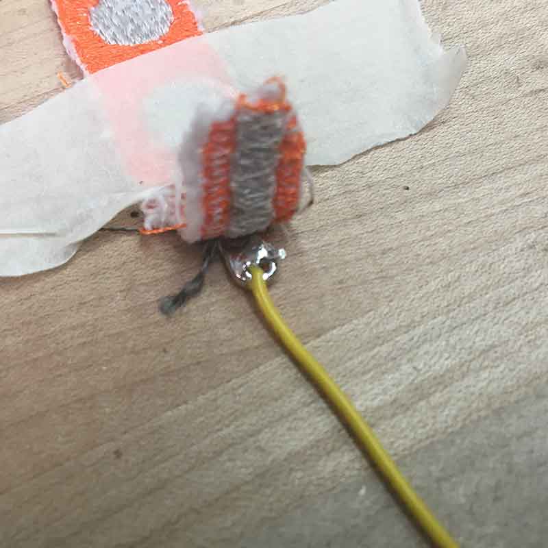
After that was done, I made sure to add some heat shrink to isolate it from the other side of the button.
For the other side of the button, I simplified the connection. I simply sewed in some conductive threade directly over the hook-up wire. This ended up being enough. When I make future buttons, I will only do it this way.
Once it was all set-up I attached the button to a breadboard and tested it out. In this video clip, I am testing the signal using the Arduino IDE. You can see the 1 for HIGH and 0 for LOW proving the the button actully works.
CIRCUIT DESIGN
The main component for my Final Project has been the circuit design. Throughout the Fab Academy, I have tested out different ideas. I first adapted the initial Hello Board from the Week 9 Embedded Programming assignment to be able to output to Neopixels. I followed this by making the circuit circular to fit in the middle of the Neopixel ring. I also played with different ways of getting the wiring to the back of the circuit where everything will be connected. This usually required me to drill holes in the board and passing flexible wire between the back of the board and the pins.
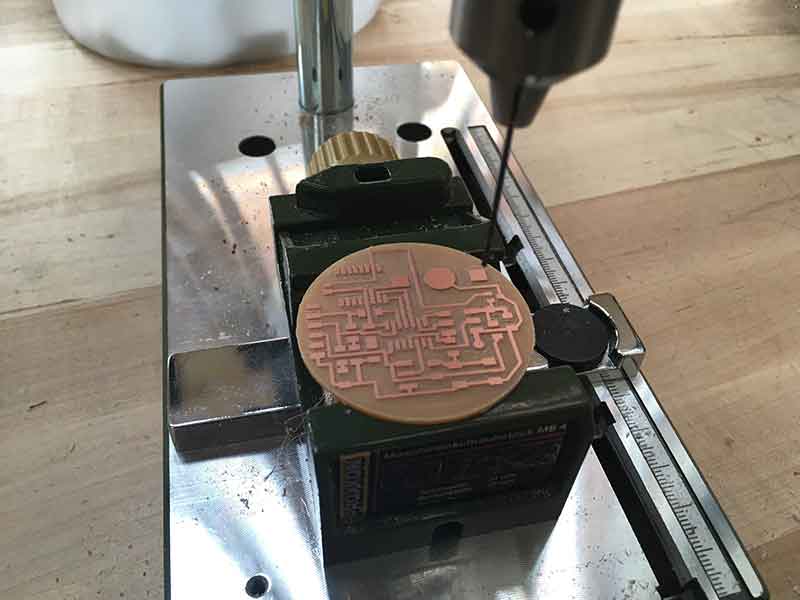
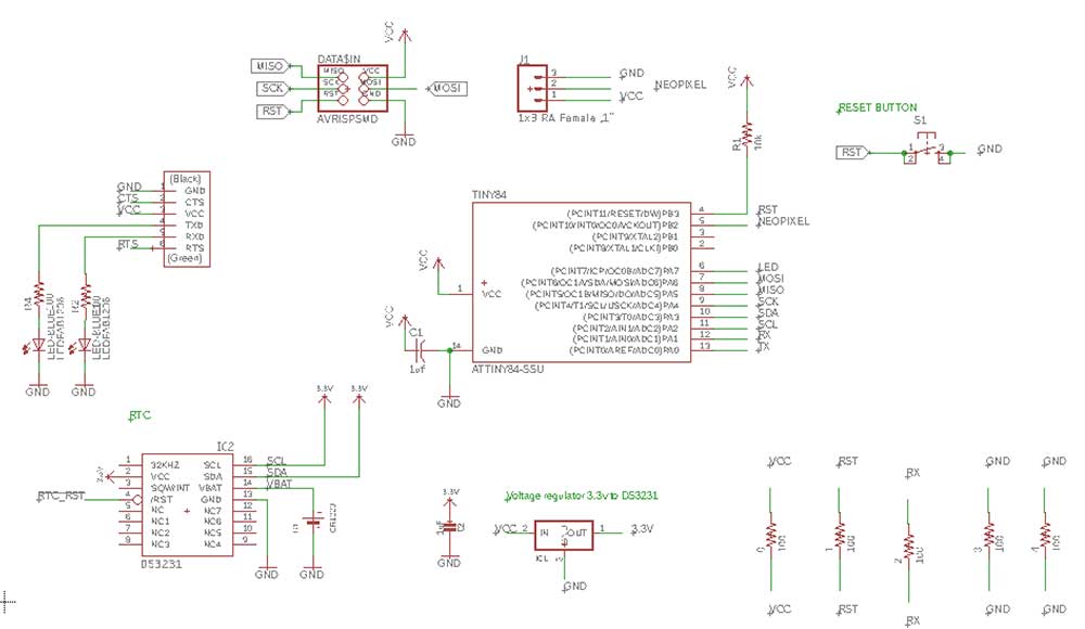
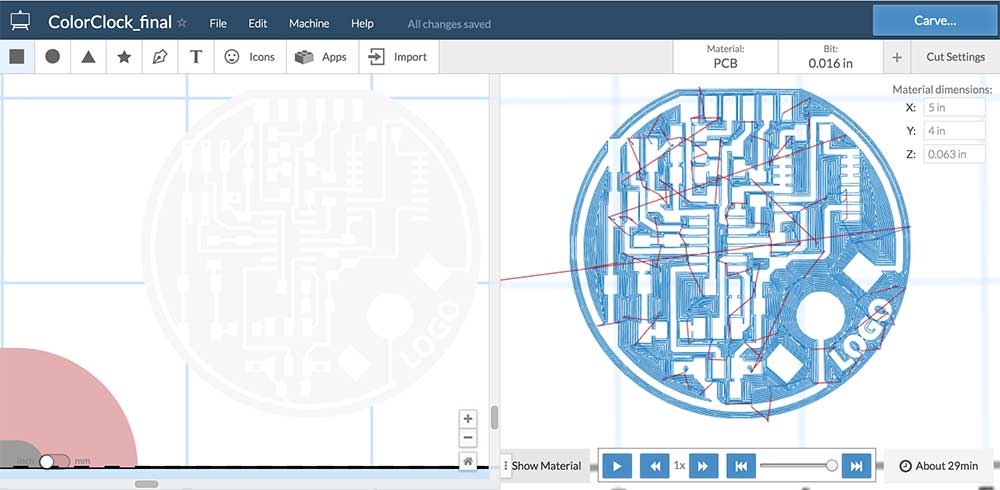
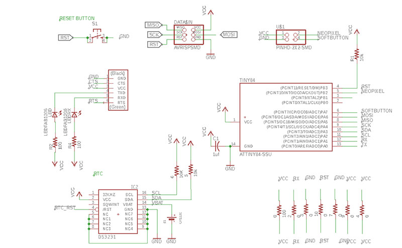
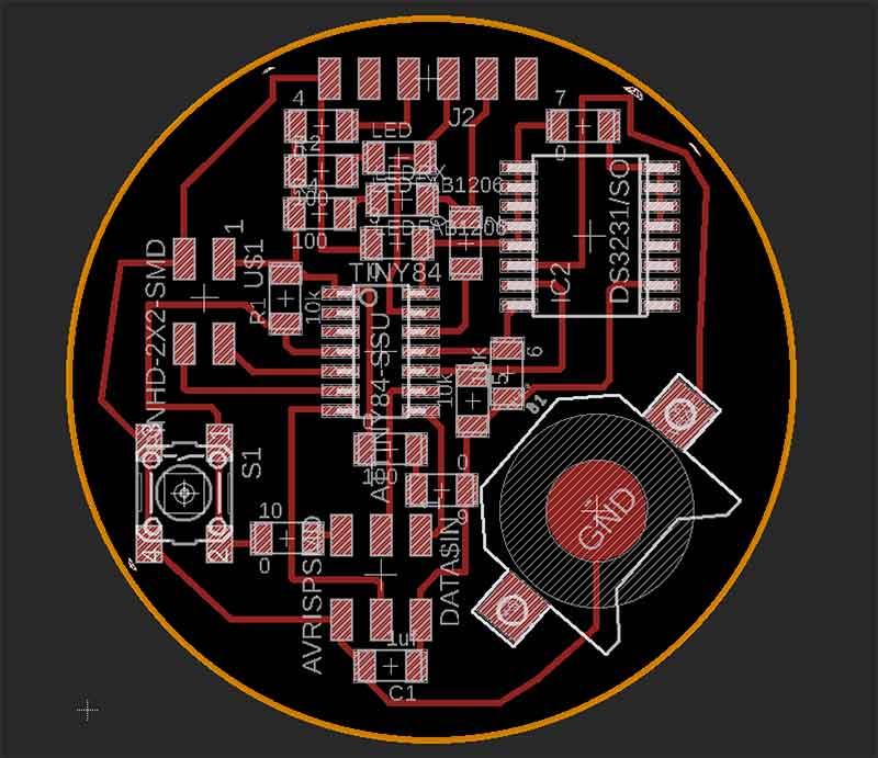
The final version of the Color Clock circuit inlcuded pins connected to the output of a Real Time Clock (RTC) as well as adding traces for the Neopixels and the button. Lastly, adding two wires so that VCC and GND could be passed to the back in the event the clock were to run off of a 5v supply. Milling the circuit is the exact same process that has been done in previous assignments using the Carvey Machine. For more info on this, visit assigments on Week 5 or Week 7.
Milling the first version of the Color Clock board went without a problem. By this point I am fairly comfortable with the machine. I have learned the best methods to get the best depth as described in previous assignments. I added a couple holes and extra traces to power the board from a 5v source.
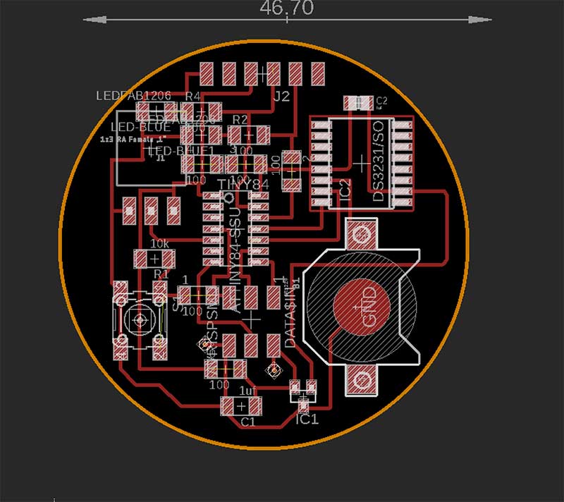

The Color Clock is essentially two chips. An ATtiny84 and a DS3231 Real Time Clock. The RTC only requires 2 pins to interact with the ATtiny84:
---> (RTC) SDA to PA3 (tiny84 - pin 10)
---> (RTC) SCL to PA2 (tiny84 - pin 11)
Other than that there are only three other connections for power VCC, GND, & VBAT. VBAT is 3v supply from the coin cell battery which allows the chip to retain memory of the initial time setting even when the chip is powered off. In total there are only 5 pins out of the 16 that need to be conected.
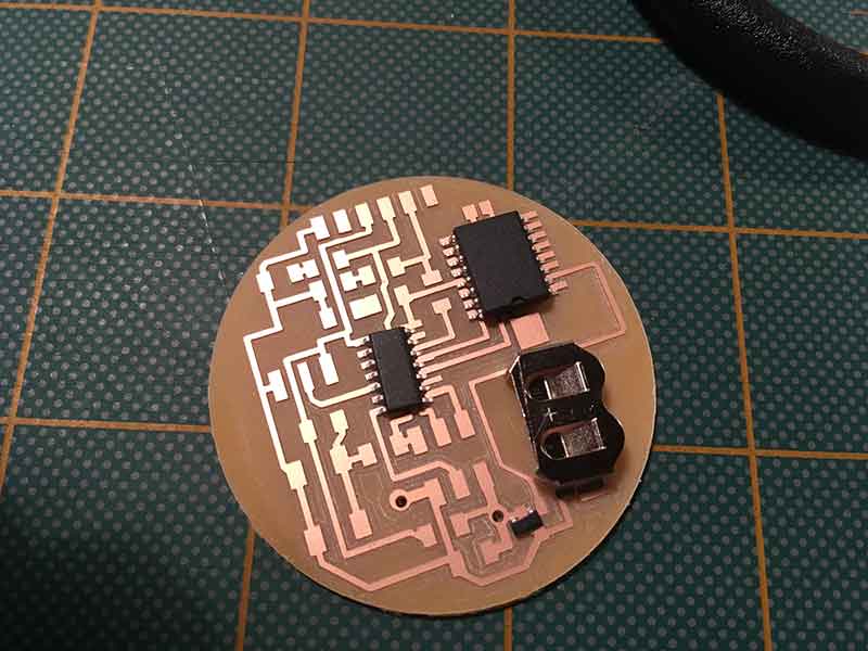
The first version of the clock chip did not include traces for a preset button. This was added in the following version. The completed 1st version of the circuit included the following features:
---> RX TX Led's for feedback
---> reset button to reset the clock data
---> 5v-3v ic regulator to run the clock chip
---> 1uf capacitor for both 5v & 3v lines.
---> three traces for the Neopixels comming off of PB2 which is the 5th pin on the ATtiny84.
I made the choice to use a lot of 0 ohm jumpers. While I hope to continue evolving this circuit and playing with the look of the layout, my priority was having it work. If this project ever develops into a viable product, multi-layer boards can be explored.
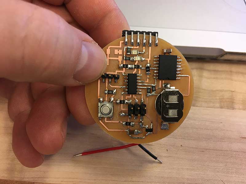
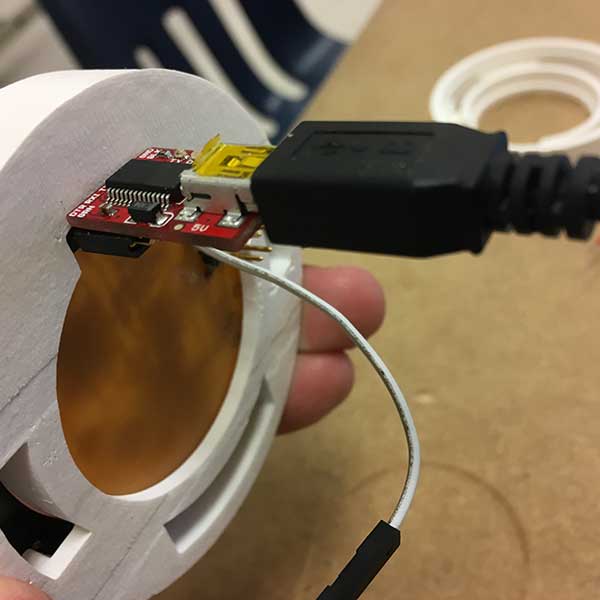
One of the more fun aspects of making thsi board was designing how to have all the inputs and headers out the back of the circuit. I took the FTDI header pins I had and bent them at a 90º angle. I also drilled holes into the PCB to pass hook-up wires for power. You can see me testing these ideas in different assignments.
Turns out I made several mistakes with my circuit. Luckily, I was able to address them all without having to mill a new board.
1) RX TX LEDs wired to the GND needed to be switched to VCC.
2) I forgot to add pull-up resistors off the clock chip pins.
3) Turns out the RTC can run on 5v as well as 3v so I do not need the regulator.
4) Without the regulator, the 1uf capacitor between 3v and GND for the RTC is not necessary.
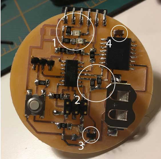
On this first version, the three pin headers for the Neopixels are on the front of the board. This will be changed in following versions. I was very happy to get this board working. The process is the same as described in the following steps. For the sake of brevity, I will only describe this step with the final version but I did get the clock chip and the Neopixels working on this version. The regulator and extra capacitor were simply redundant but did not impede the circuit from working.
---> 2nd version
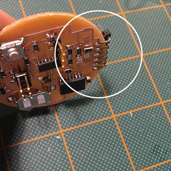
The second version of this board fixed many of the mistakes of the first. The RX & TX LEDs were fixed, I added traces for the pull-up resistors on the clock chip, I removed the regulator and extra capacitor. I also added the traces for the button pin and passed it along with the Neopixel pins to the back of the board. I had some issues with this so I had to use a white jumper instead.
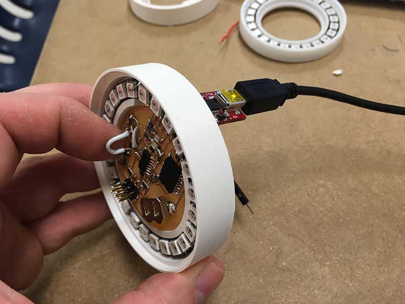
At this stage in the design process, I also started testing the fit with earlier versions of the 3d printed core. I added a flattened edge to the round circuit to better fit the bent FTDI connectors and made the necessary gap in the holder to fit these pins through.
Aside from a couple broken traces that needed patching with hookup wire, this board too also worked.
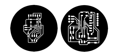
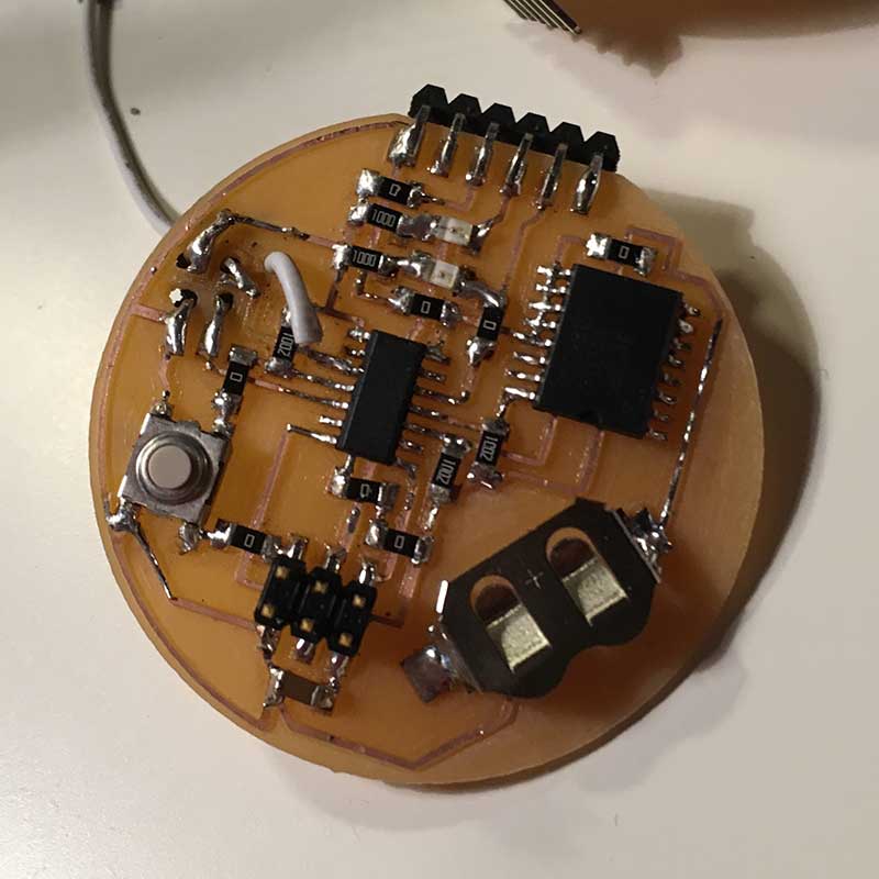
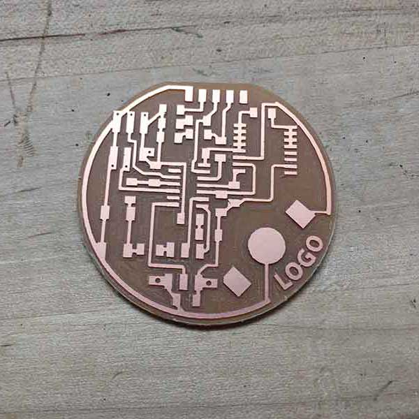
---> 3rd version
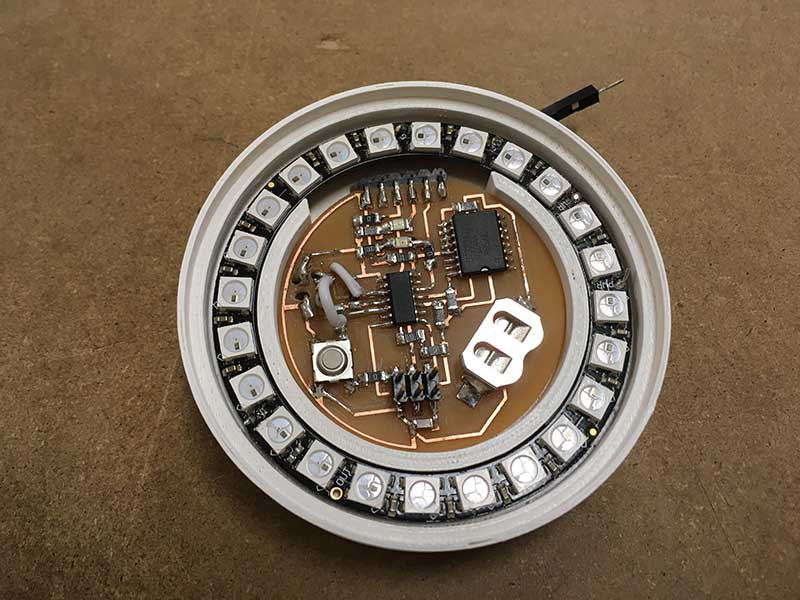
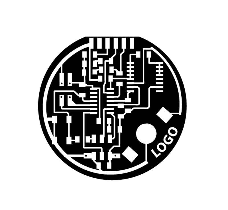
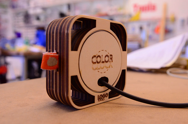
The 3rd version of the board is a bit more playful. I added circular traces for the GND and the VBAT on the color clock just to give it more of the look of a time piece. I also added "Logo" to the board just as a fun reminder. The milling process was the same.
I was really happy with the look of the board. Now that I have successfully tested function, I was able to play a bit with the look. I fixed some of the traces for the Neopixel pins just so it was easier to drill holes and have more surface for soldering making the joints a bit stronger.
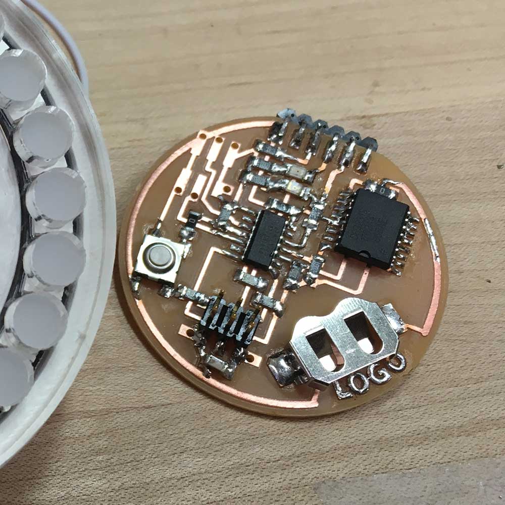
The circuit worked yet again. I am happy with my progress. You will notice in the following image yet another white hook-up wire. This was the result of a mistake. I had my button pin located on PB1 which did not have an ADC to convert the analog signal from the soft circuit into a digital one. As a result, I moved the pin to PA7 which is the 6th pin on the ATtiny. This pin has an ADC. I was unable to read the data from my button until I made this important change.
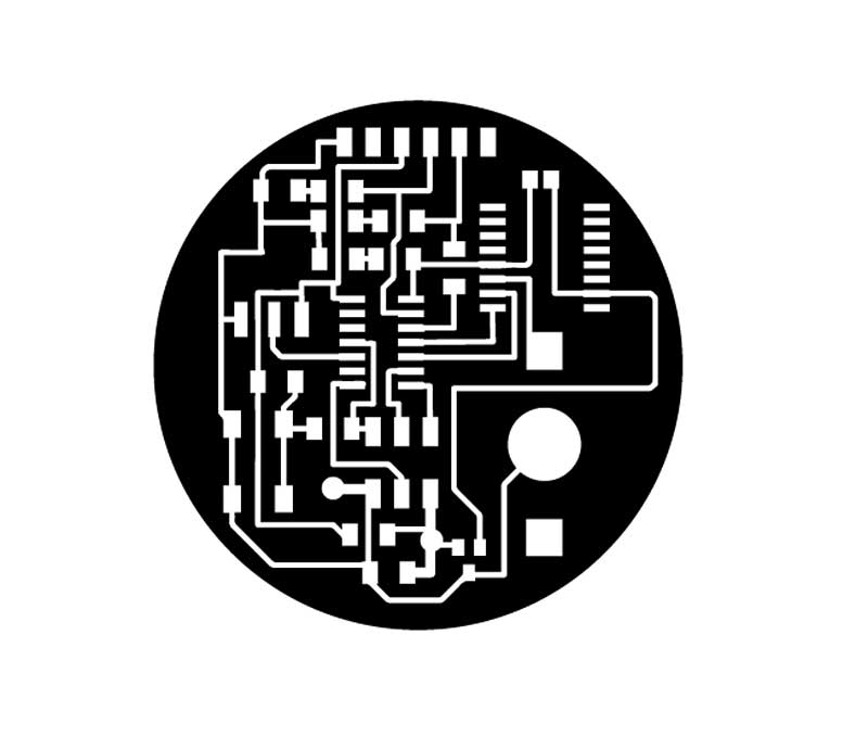
---> final version
The 3rd version of the board is the one I used for all my demonstrations. Essentially it is the final prototype. However, I did change my Eagle file to address the change in the button pin. This version is the file that is being shared.
A couple small changes were made to the thicknesses of some of the traces but this final board is identical to the previous. Aside from changing the location of the push button pin most of the adjustments were made in Adobe Illustrator on the exported monochrome image.
CLOCK ASSEMBLY
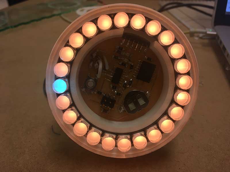
Assembling the Color Clock is easy. On the back side of the circuit here are six pins. Three for output to the Neopixels (5v, OUTPUT, GND). Three for the input of the push-button sensor (5v, INPUT, GND).
The entire Color Clock can be assembled with 13 pieces. The only pieces that were not made in the Fab Lab include the Neopixel ring and the electronic components.
---> 6 x laser cut slices
---> 2 x 3d printed parts
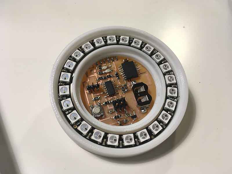
---> 1 x Neopixel 24 5050 RGB ring
---> 1 x embroidered soft circuit button
---> 1 x custom circuit board
---> 1 x 6mm laser cut cast acrylic ring with duffusion dots
---> 1 x back plate with engraved logo
Here are the steps to assembling the color clock.
STEP 1: Snap the Color Clock circuit into the front of the ring holder / 3d printed core.
STEP 2: Snap the Neopixel ring into the front holder and pass the wires through to the back. Make sure the white wire is at the top (this is equivalent to 12 on a clock)
STEP 3: Press-fit the back of the ring holder onto the the front. Make sure the small gap is to the right of the FTDI headers
STEP 4: Flip the clock to expose the back side. Take the Neopixel wires and connect them as shown in the diagram above.
STEP 5: Slide in the soft-circuit button through the small hole in the 3d printed core.
STEP 6: Connect the button wires to the header pins as shown in the diagram above.
STEP 7: Slide 3 of the laser cut slices on the front of the clock.
STEP 8: Slide the 1 laser cut slice with the gap over the button.
STEP 9: Slide the remaining slices over the back of the clock.
STEP 10: Pass the FTDI-USB cable through the back plate and connect it making sure that GND is on the right. Close the clock by snapping the back plate into place.
STEP 11: Flip the clock over and and snap the diffusion ring over the Neopixel ring making sure the diffusion dots are aligned over the LEDs.
STEP 12: Move the slices around or keep it clean. The clock is ready to program.
BILL OF MATERIALS
This project was made from laser cut scraps which is something I am hoping to encourage for future versions.
The current cost to make a Color Clock, not including taxes is:
---> $44.16 for the electronics.
---> $15 worth of materials for this clock assuming it was made from new materials.
The bill of materials for the Color Clock can be found here.
---> Bill of Materials
Here are the most expensive parts. If they can be removed through design we can lower the cost of the board.
---> Neopixel Ring - 24 RGB 5050 /// $13(generic brand) - $18(Adafruit)
---> DS3231 Real Time Clock /// $8.35 USD
I would like to add USB to serial conversion in a later versions.
---> FT232R - FTDi to USB /// $5 USD
INSTALLING LOGO
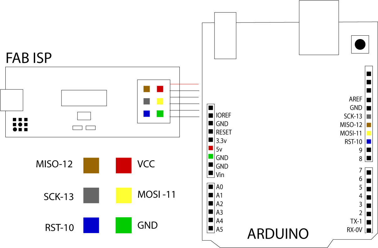
Installing microLogo on the Color Clock circuit is fairly straight forward. It is important to note that some minor work needs to be done to Brian's bootloader to be able to use the FabISP as a programmer. This is simply because the FabISP is a generic USB device and is not searchable with a port number. At the moment, the only method I know how to flash the board is by signaling to the port of the Arduino I am using as an ISP. I will update this page once this has been resolved. For the sake the final project, the installation was done with an Arduino and following the hook-up diagram from Week 5
Installing the bootloader only needs to happen once at the very beginning when flashing your microcontroller or if you need to recover from a programming issue and wish to reset the microcontroller.
STEP 1 – Download microLogo.
---> LOGO - Tiny84a-18-06-02 (installation guide, bootloader, programmer, logo-vm)
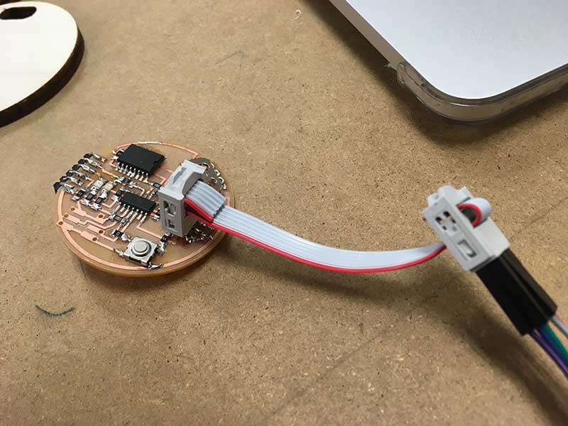
STEP 2 – Connect the necessary hardware.
Connect your programmer to your ATtiny-based board. In this case, an Sparkfun Redboard / Arduino Uno with the Arduino as ISP sketch installed.
STEP 3 – Installing the Logo bootloader.
---> Navigate to the Logo folder containing containing bootloader.hex
---> Copy the lines of code below & paste it into your terminal - then hit enter. This loads the bootloader onto the ATtiny84.
/Applications/Arduino.app/Contents/Java/hardware/tools/avr/bin/avrdude -C/Applications/Arduino.app/Contents/Java/hardware/tools/avr/etc/avrdude.conf -v -pattiny84 -cstk500v1 -P/dev/cu.usbserial-DN0266IF -b19200 -Uflash:w:bootloader.hex:i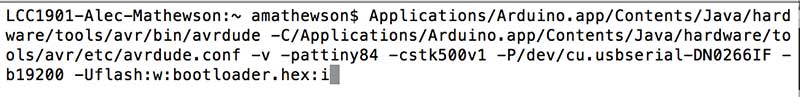
STEP 4 – Setting up the Fuses.
---> Copy the lines of code below & paste it into your terminal - then hit enter.This sets the fusess for the ATtiny84.
/Applications/Arduino.app/Contents/Java/hardware/tools/avr/bin/avrdude -C/Applications/Arduino.app/Contents/Java/hardware/tools/avr/etc/avrdude.conf -v -pattiny84 -cstk500v1 -P/dev/cu.usbserial-DN026GBP -b19200 -U lfuse:w:0xE2:m -U hfuse:w:0xDF:m -U efuse:w:0xFE:m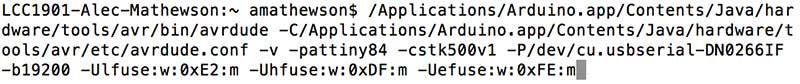
STEP 5 – Change hardware connections.
---> Disconnect your programmer from your board & connect the FTDI USB to your board.
Why do we do this? Once the bootloader is installed on the ATtiny84, you no longer need to use your programmer. The bootloader can take the signals from the FTDI or read the serial communication from your computer via usb to re-program the chip. When you receive a new chip the mcu is empty. Unlike an Arduino which already has a bootloader installed. Because we are making boards from scratch, we need a way to get the bootloader onto the mcu.
STEP 6 – Testing bootloader.
Once the bootloader is installed. We need to test that it actually worked.
a) Open “assembler.jar” in the logo-vm folder
b) Type: “send $ff print recc” in the assembler.jar window that opens.
If it is successful, you will get a response of 35 which is an arbitrary number that has been programmed into bootloader.hex as a response number.
STEP 7 – Installing Logo.
With assembler.jar from the logo-vm folder running do the following:
a) click “asm” & wait for a response
b) click “download” This will download “vm.txt” into the microcontroll
NOTE: vm.txt = implementation of Logo Virtual Machine
NOTE: this should flash the rx tx lights on your fdi board for a few seconds if you are using one.
c) close “assembler.jar”
d) IMPORTANT - unplug the FTDI cable from your board to perform a power cycle.
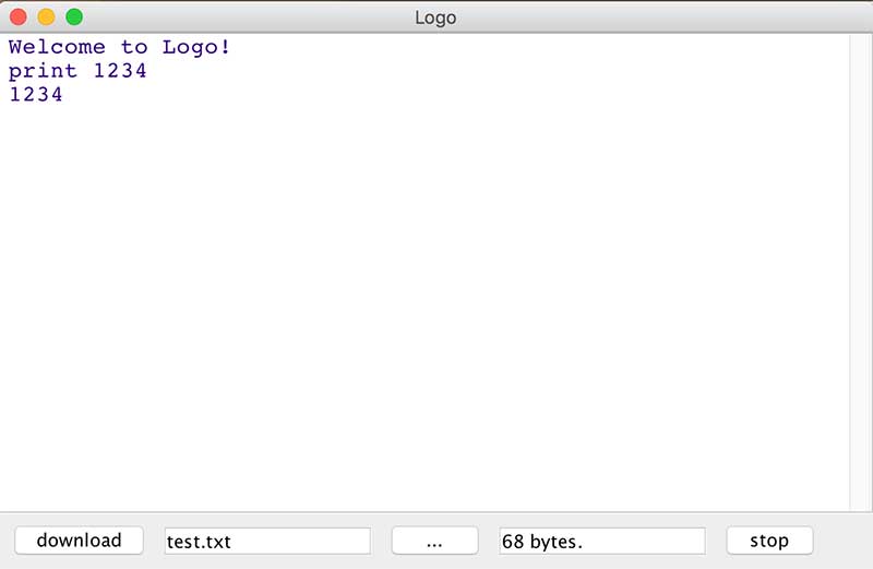
STEP 8 – Testing Logo.
a)Open “logo.jar” in the “logo” folder.
b) Type “print 1234” in the screen that opens.
c) SUCCESS: If your installation is working you will see “1234” in return
PROGRAMMING THE COLOR CLOCK
At this stage the Color Clock is ready to program. Here are some videos demonstrating the use of Logo with the color clock.
IMPORTANT NOTE: I have yet to fully document the coding of the Color Clock. It will be done during the weeks leading to FAB14
ABOUT LOGO PROGRAMMING
I am not going to pretend to be a coding expert but I will try and attempt to describe why I am so interested in Logo in particular. I am an artist learning to use code as a tool to make things happen in my work. The more time I spend playing, learning from mistakes, debugging, the better my work will be. This is where Logo shines. The one thing that is most certainly a distinction of the Logo programming language is this feature of "to" "something". I will try to make something happen. For a beginner, when you make a mistake Logo will likely still do something and the outcome of this is a learning opportunity. Think of the idea "to" "something" as name for a magic spell. As Seymour Papert, one of Logo's creators, might say Logo teaches children to think about thinking. But it was never only limited to children. Thinking about thinking is a lifelong journey and Logo can scale with exprience.
When I refer to Logo, I am actually referring to microLogo. MicroLogo, and my understanding of it, comes from Brian Silverman. Brian has influenced many Logo users but I do not know if there is a textbook or website to document it. More specifically, how we are using it here in a Fab Lab context. This is certainly not the time or place for something so in-depth but perhaps an idea for an extension of this project. I will try and give a few examples to demonstrate the way Logo works.
---> programming on different levels
One way I will describe working in Logo as I see it, is to relate it to working on different levels. The lowest level, let's call it the 1st level, resembles more closely to lower level programming languages like C. The 2nd level, looks like english with some mysterious elements. Not unlike programming in Arduino. The 3rd/highest level, is a playful and easy-to-read environment. You never have to leave the 3rd level if your code is setup to work with the given architecture of your board and all the desired functions are pre-configured. This is similar to how you would work in an object-based programming language like Max MSP or Scratch (which is essentially a derivative Logo).
Working in the 3rd level, you still learn coding structure and you get to manipulate your ideas as you would in any other programming language but the lower level "lingo" (the stuff the looks like "gobledy goop") is translated into words. This is where the playing in Logo happens.
To translate lower level features, you need to write functions ("to" "somethings") as well as the standard directions which your hardware requires. LightLogo, is a version of microLogo that Brian Silverman designed. It was initially written as a way to play with Neopixels on a chosen hardware platform like an Arduino Uno or an Adafruit MetroMini. In LightLogo, you do not need to access bit registers, or the kind of memory you want to target in your code. This is done in the lower levels. LightLogo is essentially custom library in microLogo. Here is how you would blink a set of Neopixels working in LightLogo or this socalled 3rd level of microLogo:
To blink
loop [all red
wait 10
all off
wait 10  ]
end
When you call "blink" your code will be executed. In the above example all, wait, off had to be defined. Let's say you want to accomplish the same thing but this time on the 2nd or lower level I was mentioning before. For demonstrative purposes, I will simplify things. There is more to the following code but I will simply highlight core elements to help with the concept I am trying to establish. On the 2nd level, the previous example could also look like this:
To blink
to all :n
let [addr 0]
repeat npix [dot :addr :n make "addr :addr + 1]
redraw
end

to dot :n :c
ifelse :c = -1 [%setc $100][%setc :c % 100]
%stamp :n % npix
end

to redraw
if shown [savepixel pos %setc $100 %stamp pos]
shift-pixels
if shown [restorepixel pos]
end

to wait :millis
redraw
mwait :millis
end
What I find nice, is you can include elements from the lower levels in the higher levels. You'll also notice, that you can somewhat follow what is happening because of the idea of using "to" "something". One of the criticisms of Arduino I have been hearing is that it hides some of the magic of coding and working with microcontrollers. It makes a "magic box" where you don't get to learn why it is "magic". Having seen a professional programmer work in Logo, I can say it looks like making magic happen. I can understand the 3rd level features move down to the 2nd and 1st levels to try and learn more about mixing code with hardware.
---> microLogo in Fab Labs
In microLogo, you can easily setup your programming environment to hide the features that address the bit registers and require moving bytes within the architecture of a microcontroller. A series of directions are assembled and loaded into the virtual memory (vm) of the processor. The vm folder contains a set of code that includes pin functions and registers and it also is where core definitions are kept.
In a Fab Lab context for example, when you are constantly designing your own boards and trying out different chips, it is important to understand how to address the registers on your board. This requires you to move into the vm code and change things. Once you know what to look for, this is relatively easy. What I like about logo, is that I find it easier to see how this is done compared to other languages I have been trying. And unlike Arduino, where many this does not get hidden. Essentially, in Logo, you are building your own modules or libraries as you work. This is extremely appealing to me and the way that I like to work. Logo uses less syntax than other languages. Brian suggested to me that surprisingly, some people find it harder to read. But for myself, and likely other creative types who are not as familiar with complex syntax structure, Logo is easier to read. I wonder if sometimes we confuse "easy" with "simple". I don't think Logo is necessarily "simple" for me. I would define it more as "accessible". Talking to Artemis about Seymore Papert's intentions, Logo was design to be accessible for kids but scalable for professionals.
Getting Logo to work on the Color Clock ATTiny84 chip required me to understand the registers, the bit locations, and how to set them up. Through Logo, I have a deeper understanding of the technology behind the microcontroller than had I just used the Arduino IDE. I also can now look at a block of C-Code and recognize more of the architecture. Here is an example of how Logo is used in the Color Clock to set the pins on an ATTiny to read the real time clock:
to clock-pin-init
writeb didr0 $0f
bsetb ddrc $30		; clock chip pins
bsetb portc $30
end

to time
gettime
prf "|%d | hour
prf "|%d | minute
print seconds
end
I was most interest in the idea that Brian and Artemis had with his Color Clock project which is to use math to make cryptic puzzles represented in light. Here is part of Brian's code that relates to the pattern making:
to go
let [h 0 m 0]
setup-clock-pins
loop
 [gettime
  make "m minute
  make "h hour
  if :h = 0 [make "h 12]
  digit 4 :m % 10
  digit 8 :m / 10
  digit 12 :h % 10
  digit 0 :h / 10
  redraw
  wait 2]
end


to digit :p :n
let [cn :n
     c 0]
brightness 8
if :n > 4 [make "cn :cn - 5]
if :cn = 0 [make "c 20]
if :cn = 1 [make "c 0]
if :cn = 2 [make "c 85]
if :cn = 3 [make "c 70]
if :cn = 4 [brightness 10 make "c 40]
repeat 4 [dot :p :c make "p :p + 1]
if :n > 5 [stop]
brightness 12
dot :p - 2 $100
dot :p - 3 $100
end
What I noticed about Brian's work with Logo is that it can be look complex or simple depending on how he approaches it whereas other languages those distinctions seem to me to be less obvious. The above code for example, is foreign enough to me to look complicated but I can still kind of understand what is going on. Other languages I have used, there seems to be less flexibilty in the approach. This is good for developing the right habbits but even with Logo, when you do something wrong you are given room to understand what it is. Here is another level to logo from a version of Brian's microLogo called LightLogo:
to startup
reset ht
setbrightness 20
go
end

to go
all red
loop
 [dots yellow
  dots blue
  dots white
  dots green
  dots magenta
  dots cyan
  dots orange
  dots red]
end


to dots :c
setc :c
setpos random 0 23
repeat 24
 [pu fd 16
  pd fd 1 wait 100]
end
In the above example, Brian has named instances for color and other features that relate to working with NeoPixels. Essentially, he has built is hown language or "library". The setup for this is placed in a syst.txt file that is pre-loaded onto the microcontroller in the setup phase. This makes Logo extremely accessible and easy to read.
Here is how Brian's color scheme broken down:
constants [[pixbuf $200][colorbuf $300][true 1][false 0]]
constants [[red 0][green 30][blue 70][cyan 40][magenta 85][yellow 20][orange 10][white -1]]
Code by Brian Silverman
For a professional artist, you can name your variables, your instances, etc. any way you like just as you can with other languages. With logo, there is a level of complexity that is easily removed allowing you to focus more on structure and output. This for me makes it a compelling language to work on for expressive applications.
PROJECT FILES
---> Color Clock 3D Files(.STL, .f3d)
---> Color Clock Body (.svg)
---> Button Design (.svg)
---> microLogo Installers(bootloader, logo vm, logo.jar, instructions)
---> BOM(.csv)

This work is licensed under a Creative Commons Attribution-NonCommercial-ShareAlike 4.0 International License.