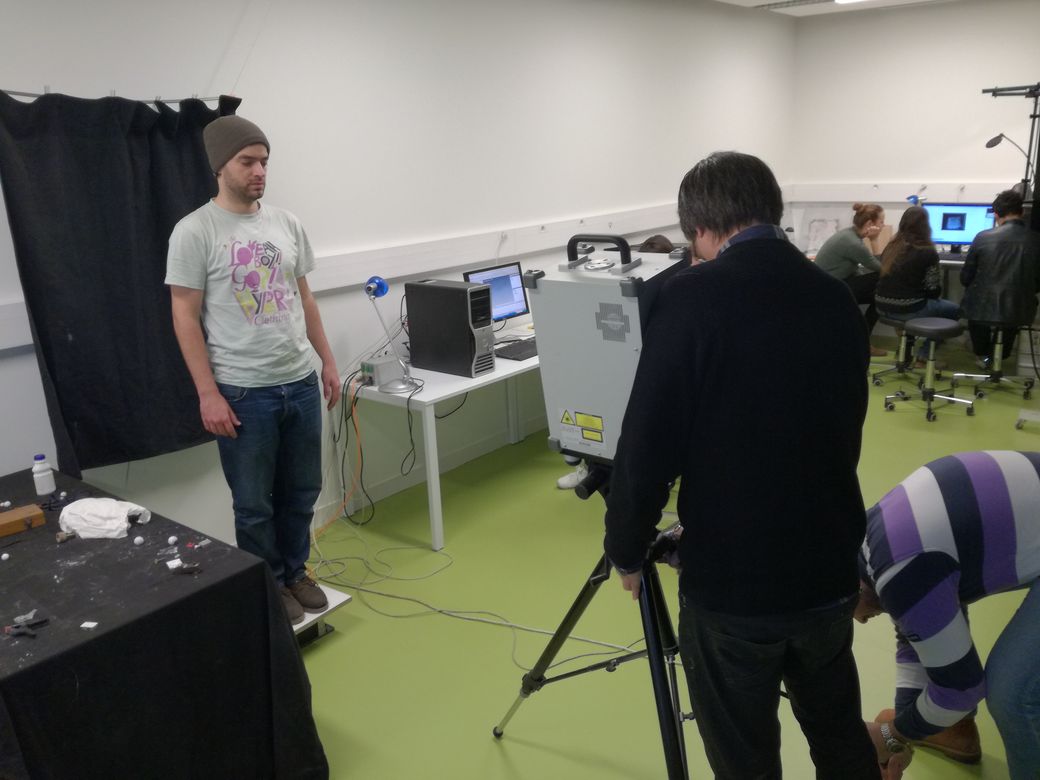
In the Digiscope FabLab, there are two "types" of 3D printers: Fused plastic extrusion (Ultimaker 2 and 3) and Photo polymerized resign (Formalbs 2). We used this 3D Printer Tolerance Test in order to evaluate their capability.
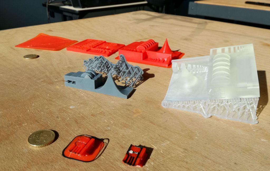
At the first try (see the grey resin print above) we had to stop the print after the first hundred layers. The print detached from the stage and stuck to the PDMS bed. It is expected from time to time (bed ages). This bug could also have happened because the model was set to be printed in a dangerous vertical orientation. It is not recommended (by Formlabs itself) to print vertically. Even though, Preform (the Formalbs slicer software) proposed this position when using the "magic wand" positioning tool... :/
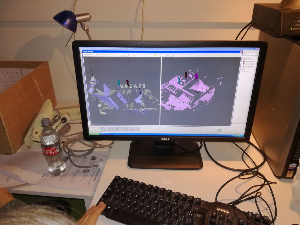
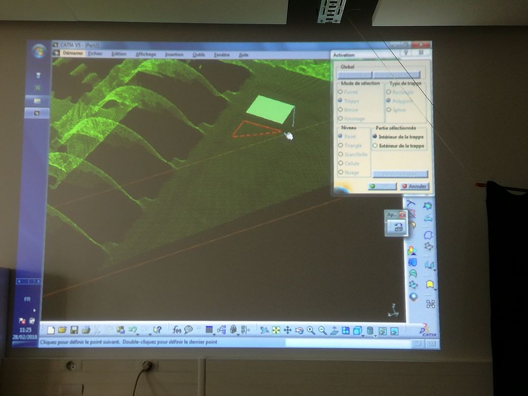
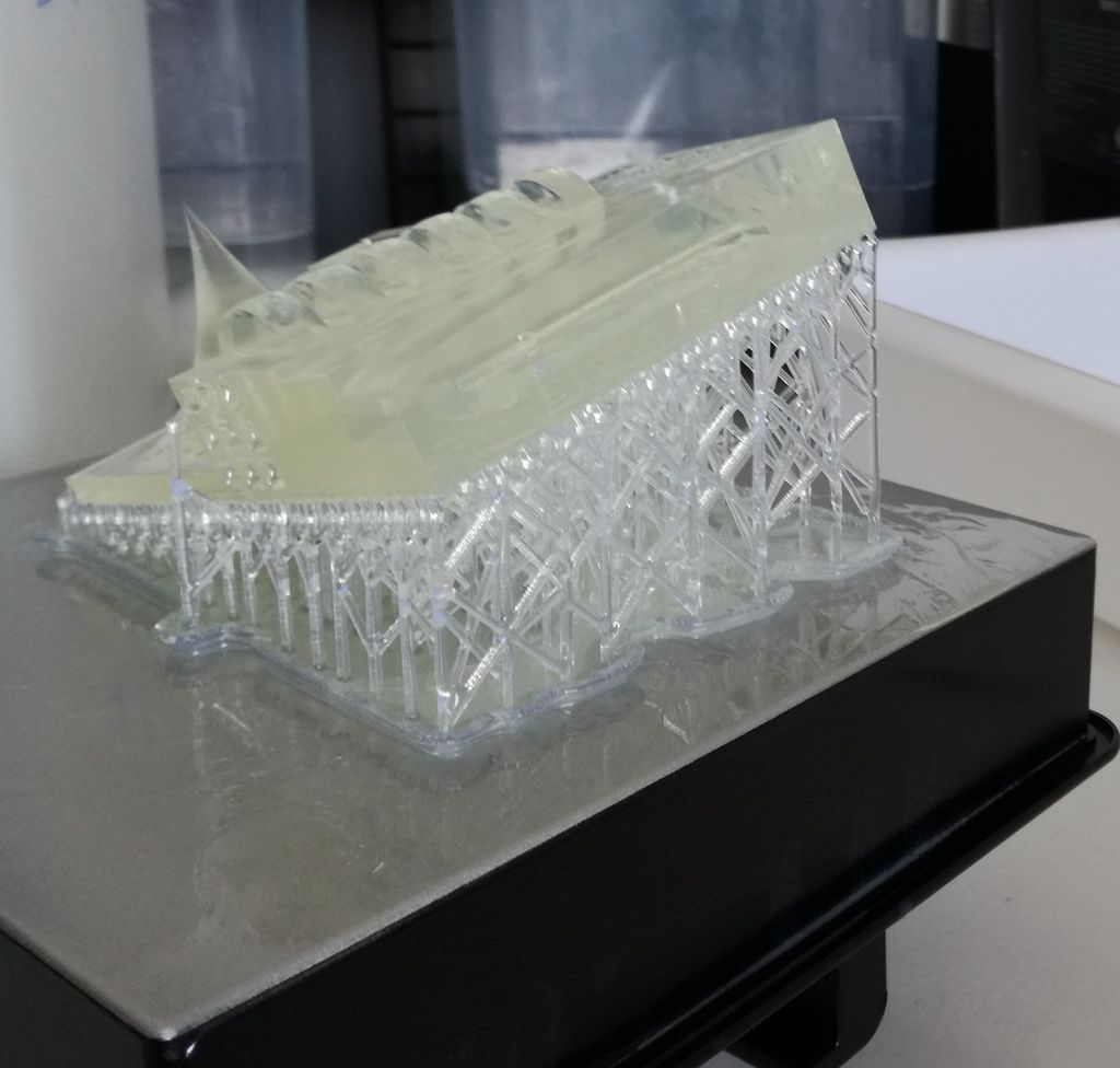
For the second try, we used a new bed (65Euro) and the "clear" resin. In Preform, following Formlabs tips & tricks, we oriented the model horizontaly with a slight tilt over Tetha and Phi (~20 degrees).
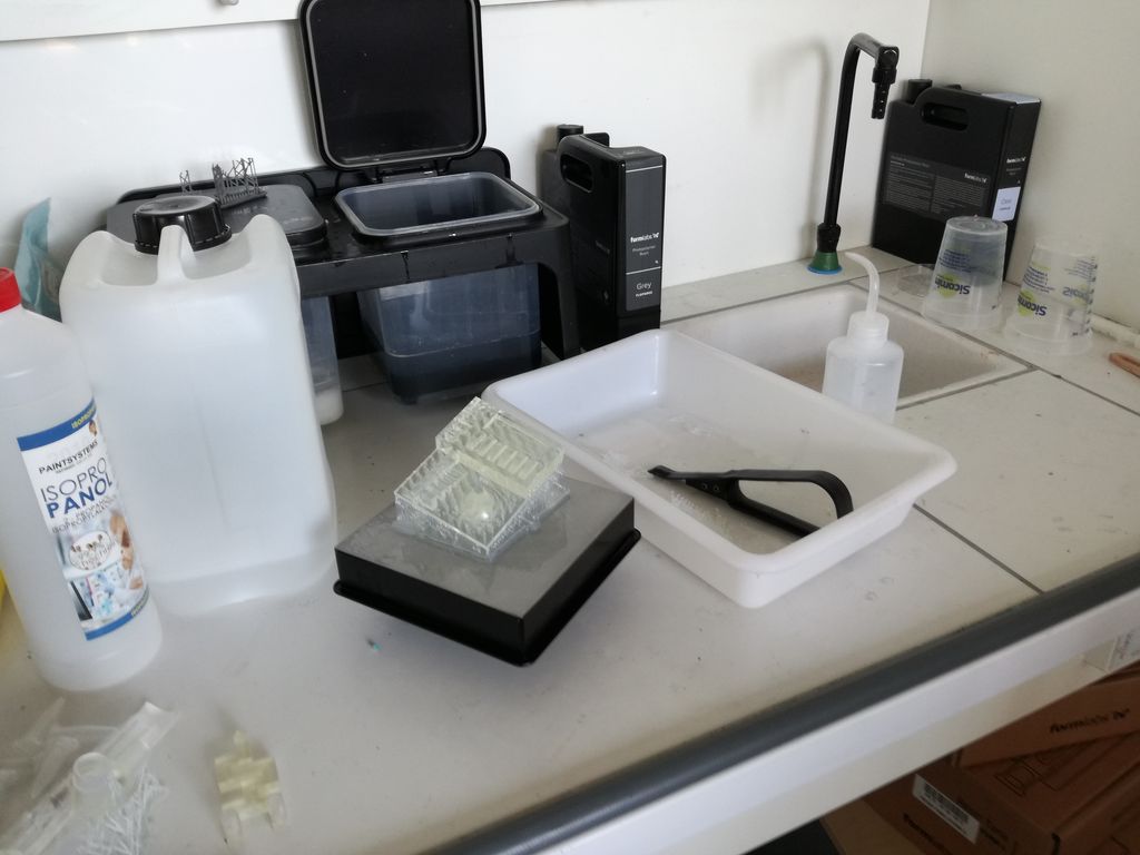
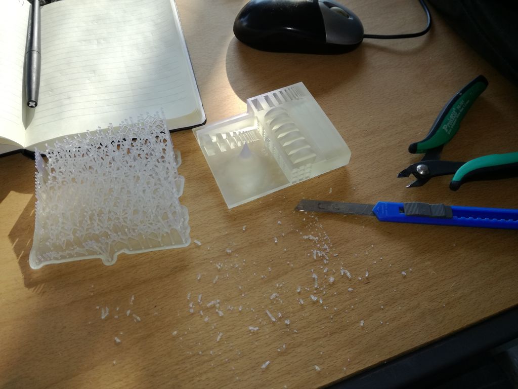
Once the printer is done, there is a lot of post-processing steps:
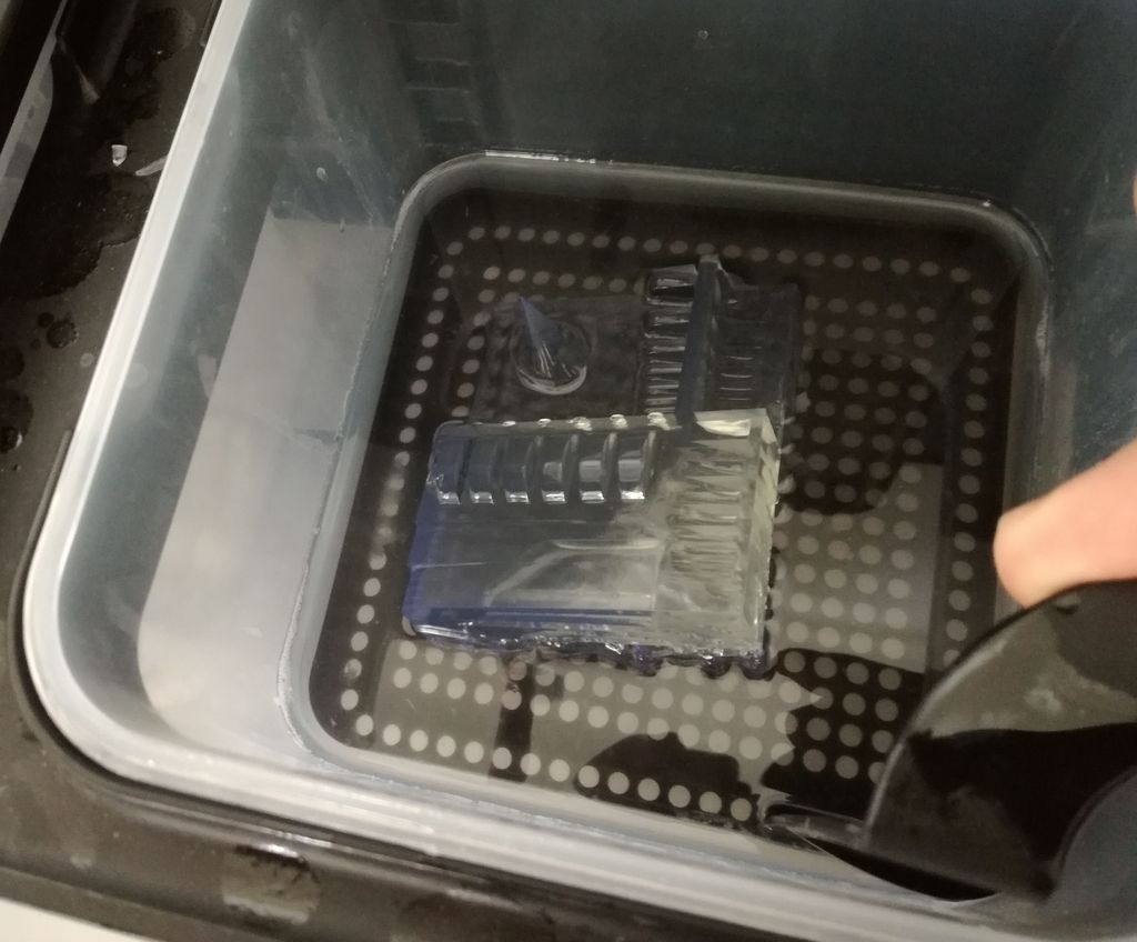
Detach the print from the stage with latex gloves, Clean the stiky resin with 2 bath of Iso-Propanol (10 mins each), Cure it with UV light (one could use the sun), Detach the support with a blade.
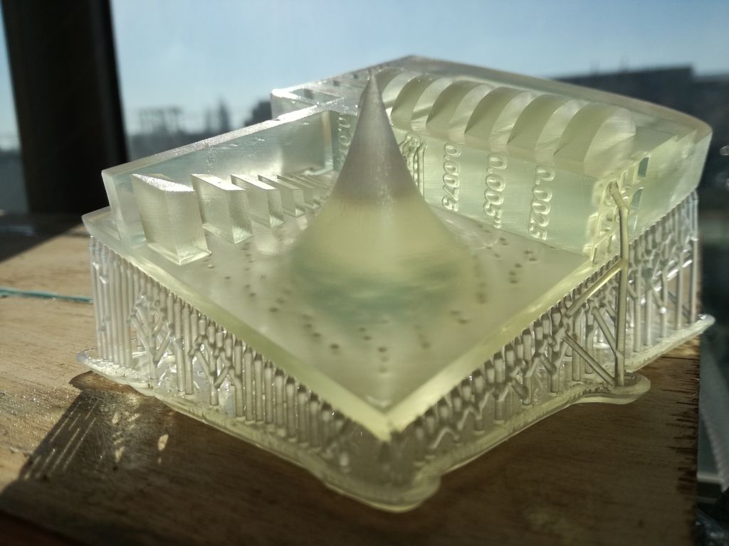
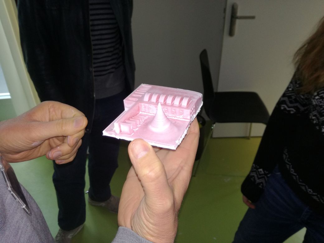
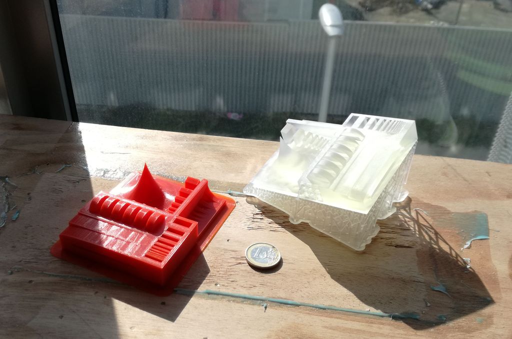
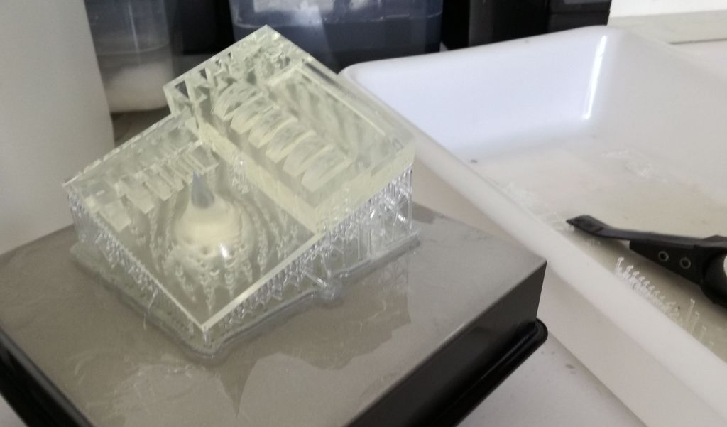
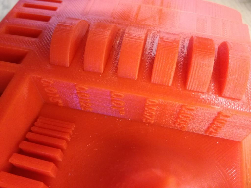
The print is very smooth. No layer can be seen.
The print is also very distorded (+/-0.5mm) on the surfaces close to where the support was attached. The little holes (eg around the wheels) were filled with resin and are not visible.
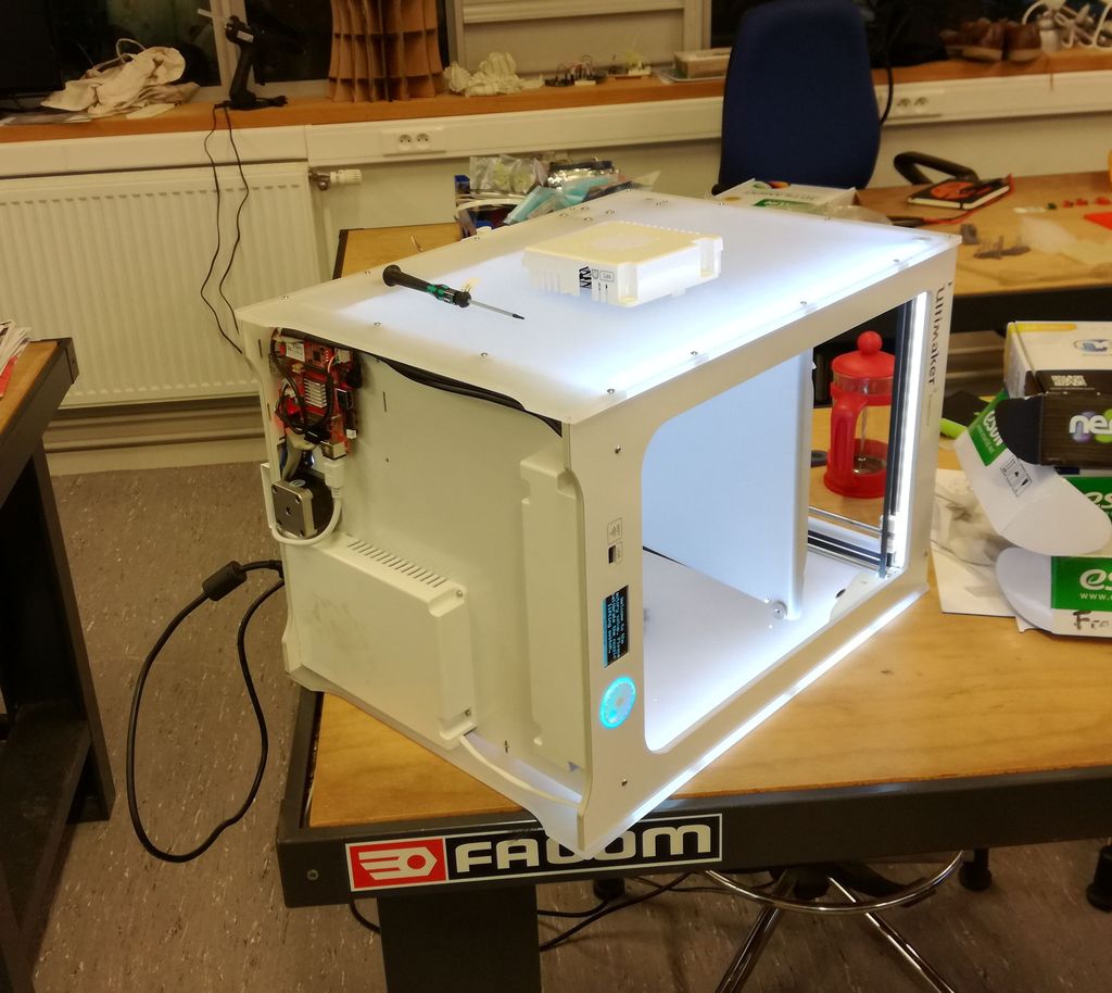
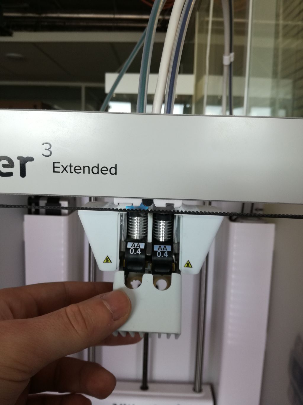
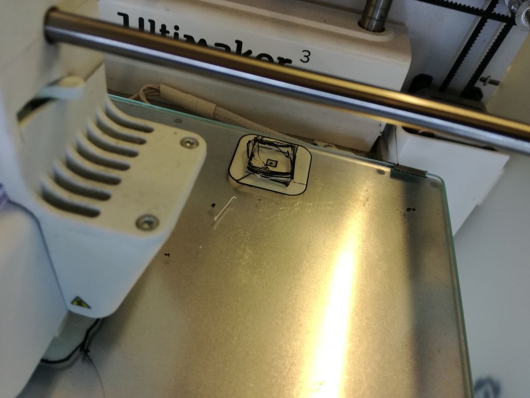
The first 2 trials failed because the plastic filamment got stuck in the feeder and therefor stopped extruding. This probably happended because we changed the plastic from flex to PLA but didn't unscrew the feeder's wheel.
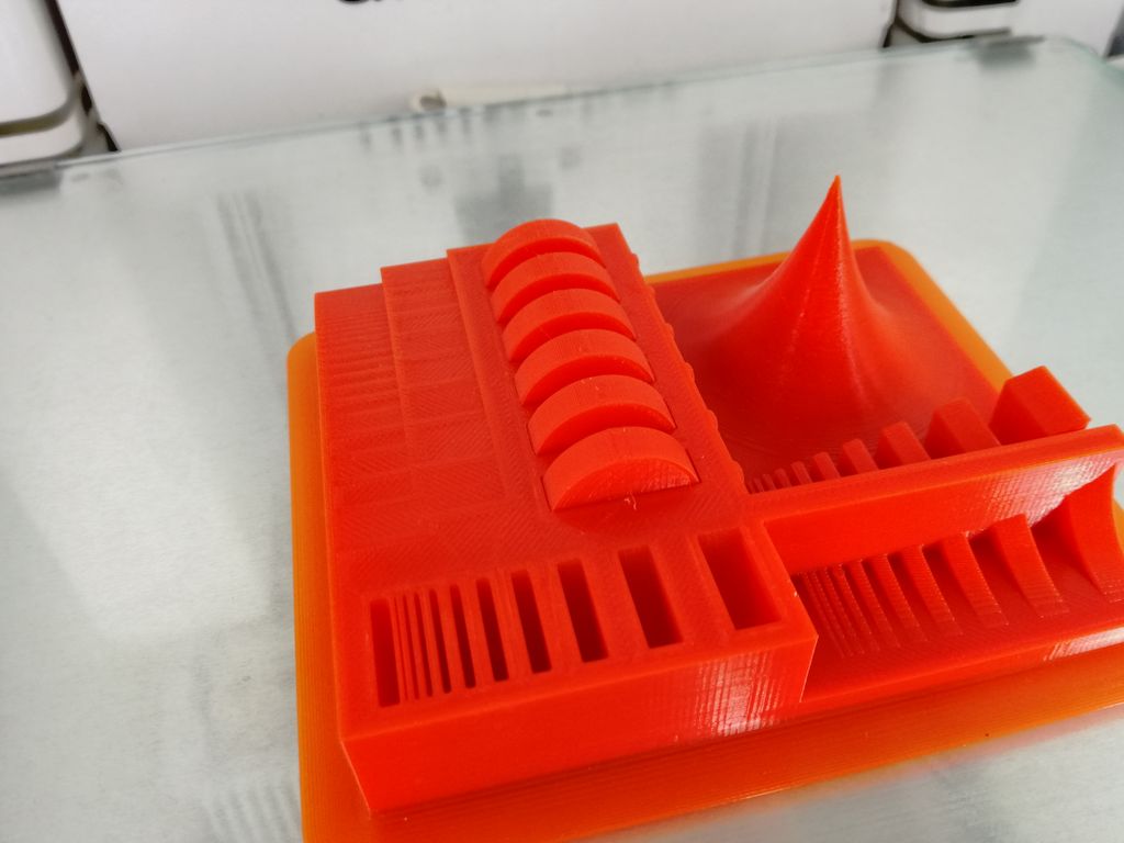
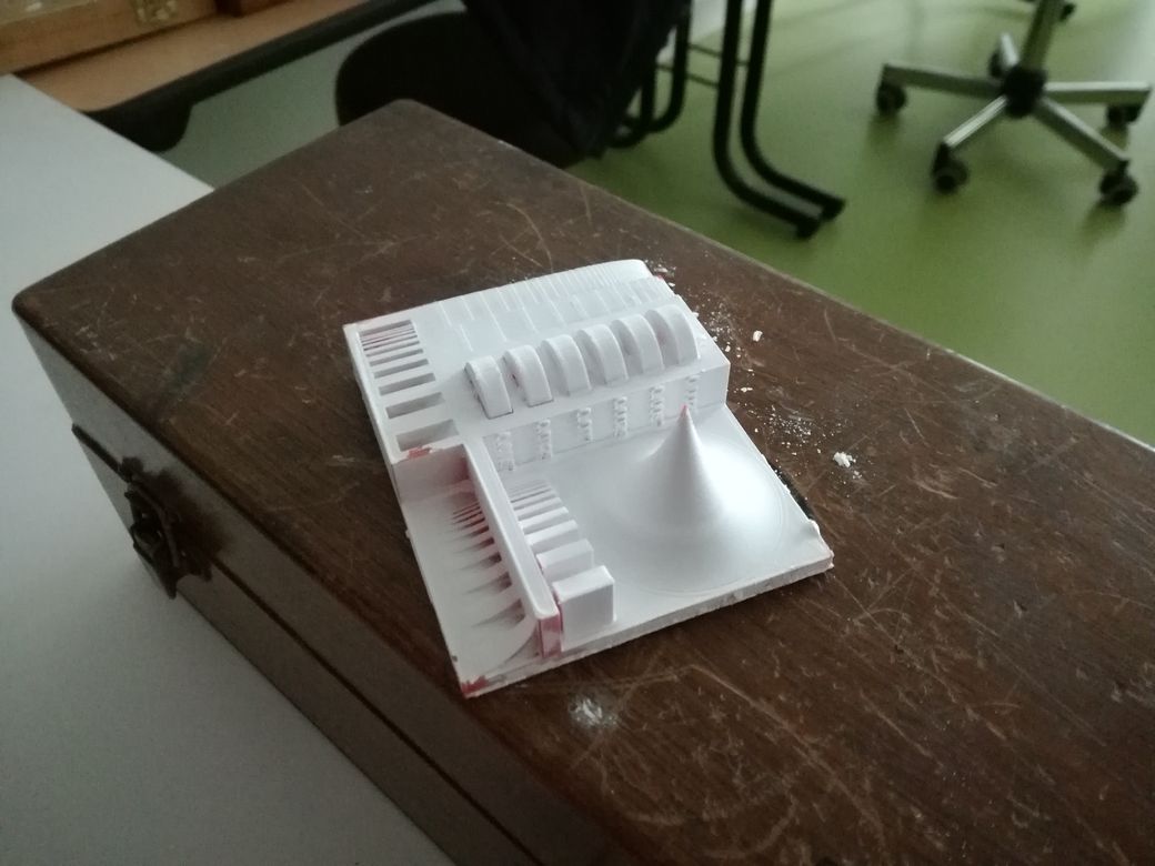
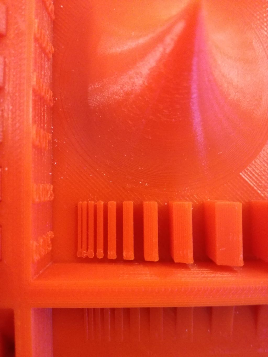
We can see that the minimal distance between walls is limited by the landing area of the nozel on the print when it changes layer (see bottom left corner)
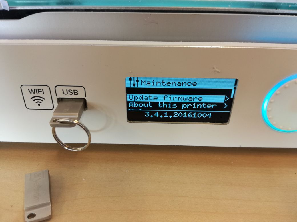
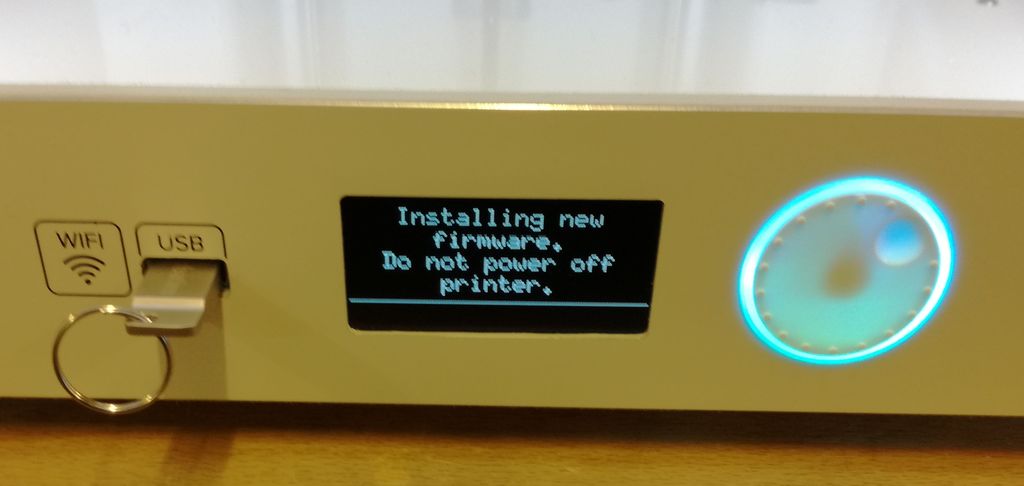
We had a bug with the UM firmware (that hadn't been changed since 2016). We fixed it. Details can be found in this issue.
None of the wheels of the test model could be moved... In order to study the space needed between surfaces that allow free-motion (ie that do not stick) we used this gauge as well as the one of MakerMuse.
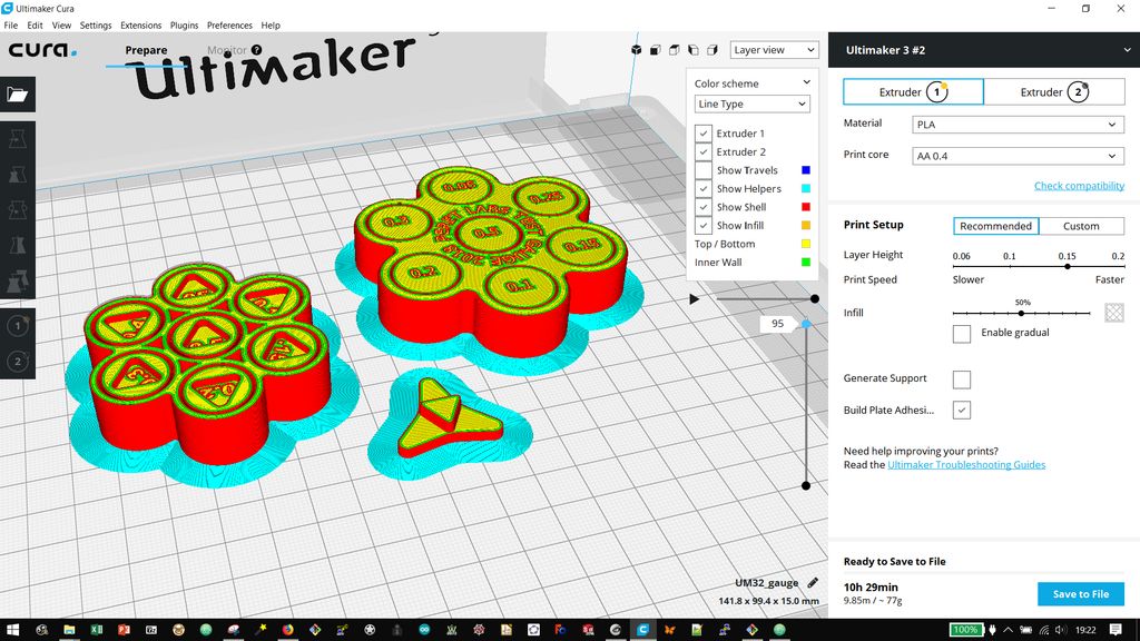
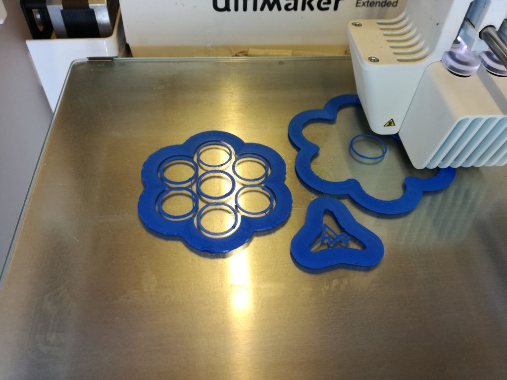
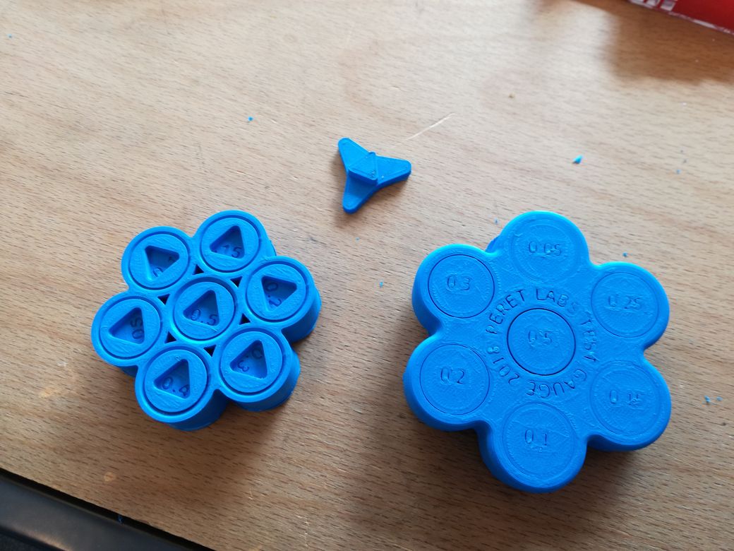
The joints with surfaces separated by 0.5mm and 0.4mm can move. The others can not :/
Next time I print a test gauge, I won't print the brim. It prevents the pieces to readilly move freely after print. They need to be removed with a blade (tedious).
The solidworks source files relative to this section can be found
this folder on gitlab.
The essential fabrication files are those two .stl files:
for the body of the model and
for the tracks of the circuit.
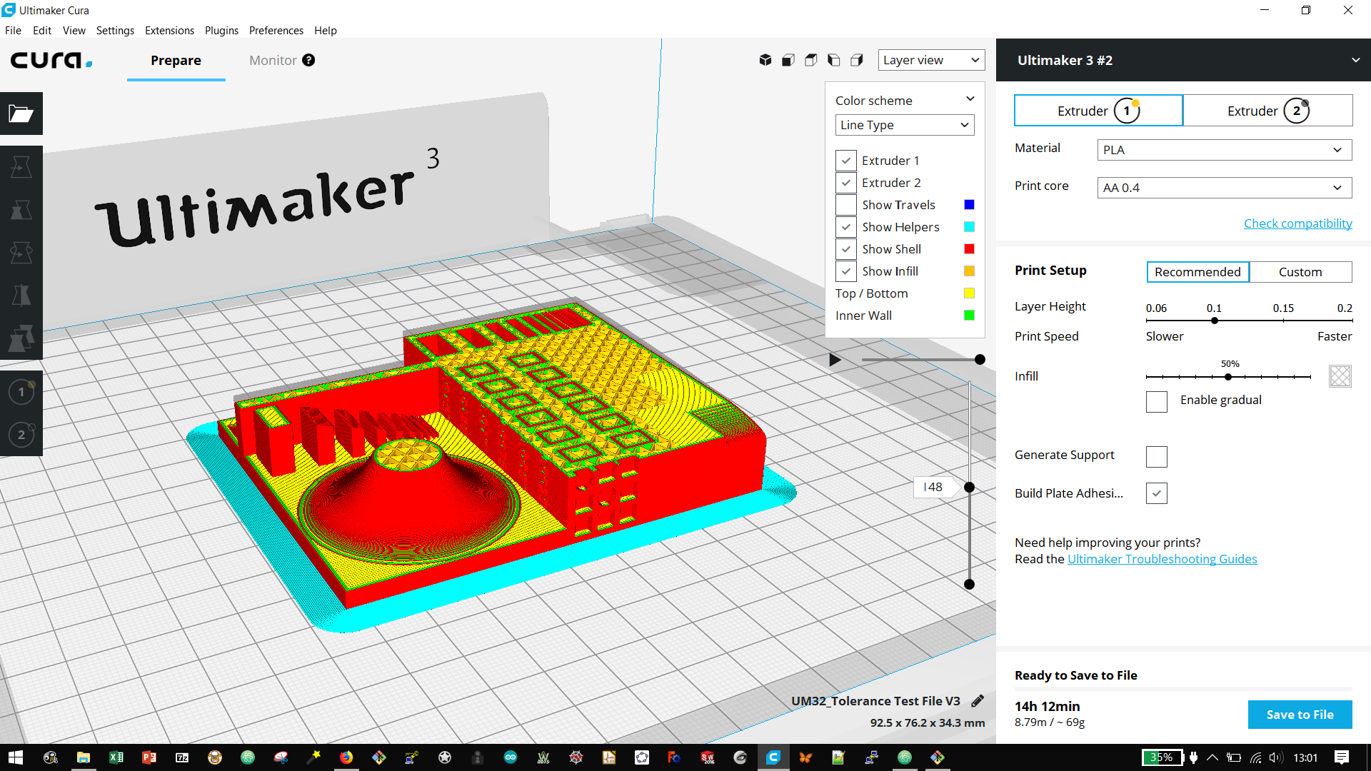
You can also directly download this cura-ultimaker project where the files are already merged.
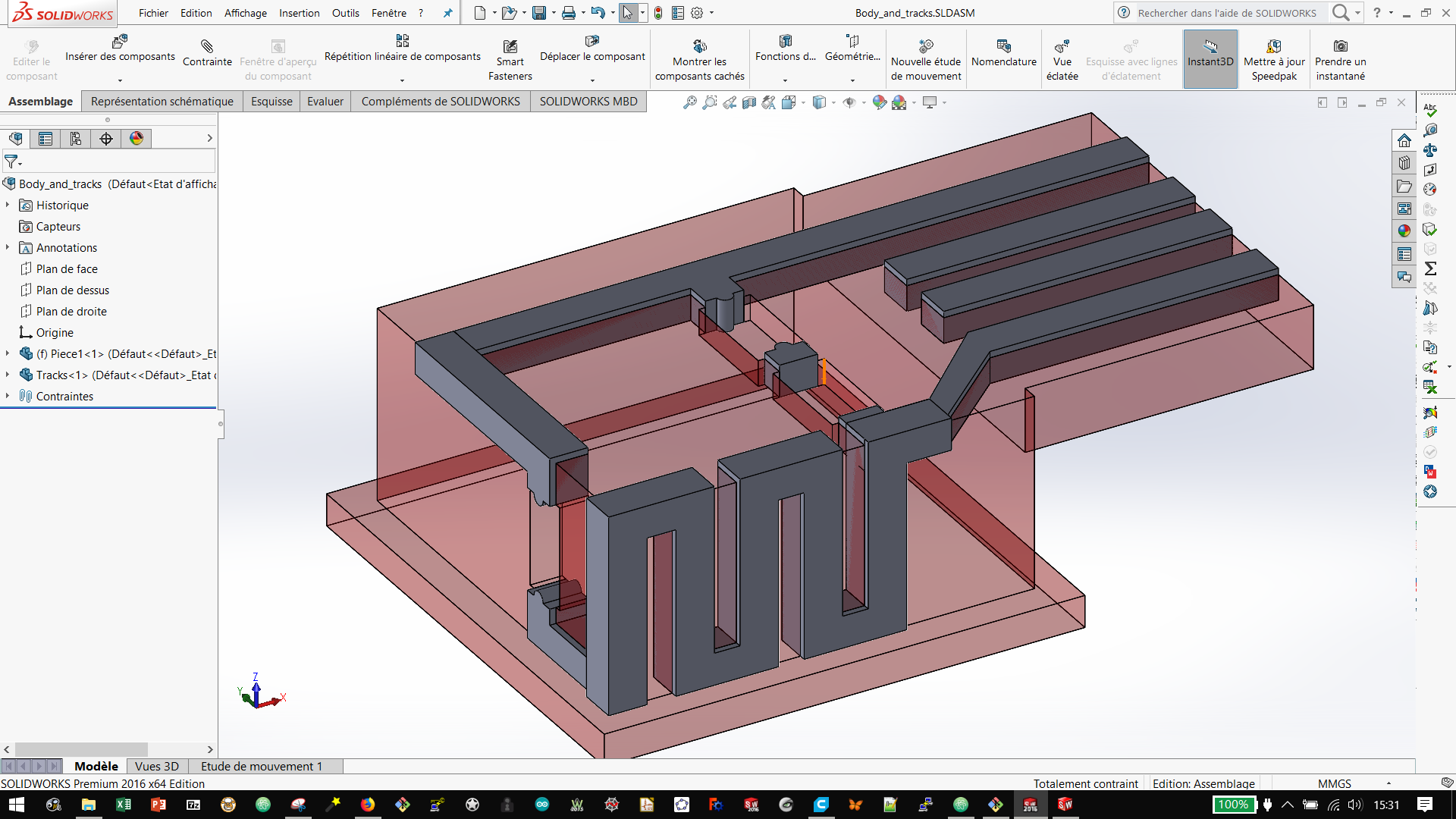
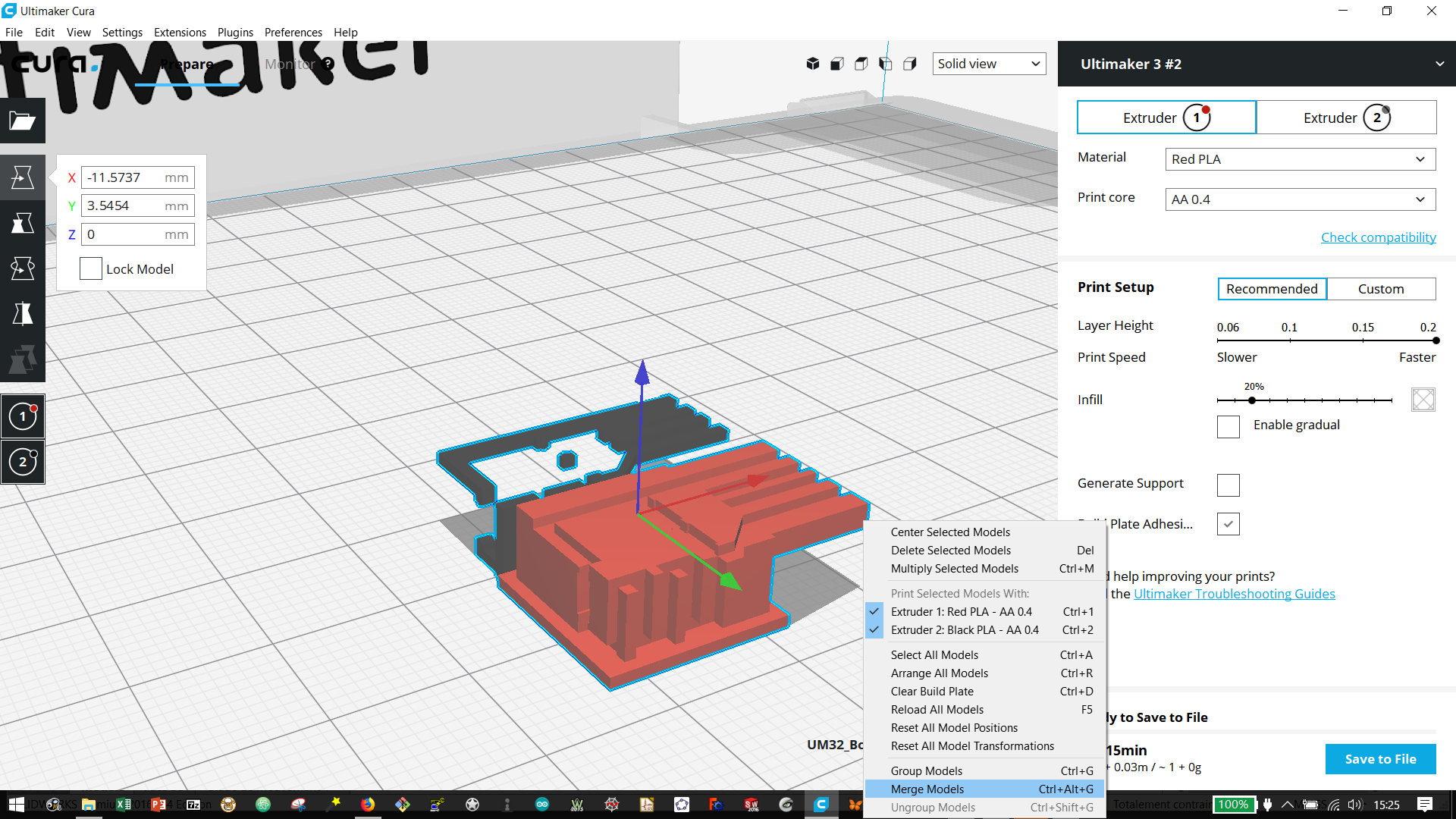
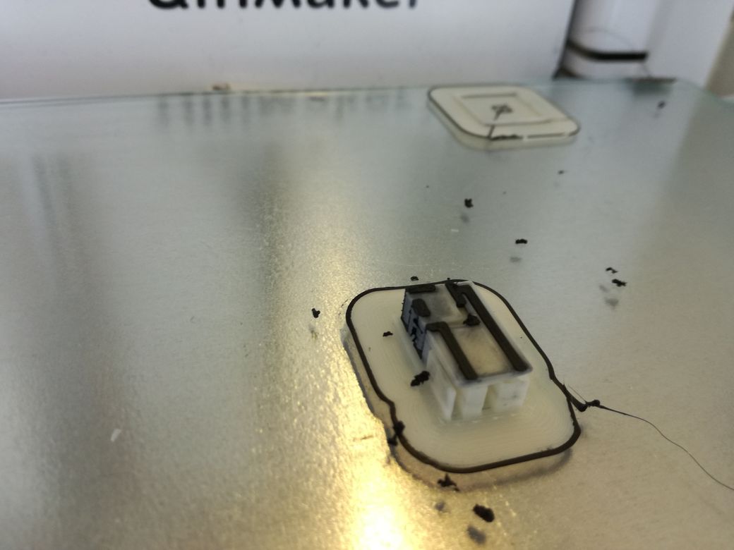
Using the double extrusion ability of the UM3, we wanted to print a USB-plugable circuit that drives two 1206 LEDs.
For the tracks, we used this material from Proto-Pasta, for the body we used red PLA.
We use the heat gun to soften the plastic and insert the 1206 componants.
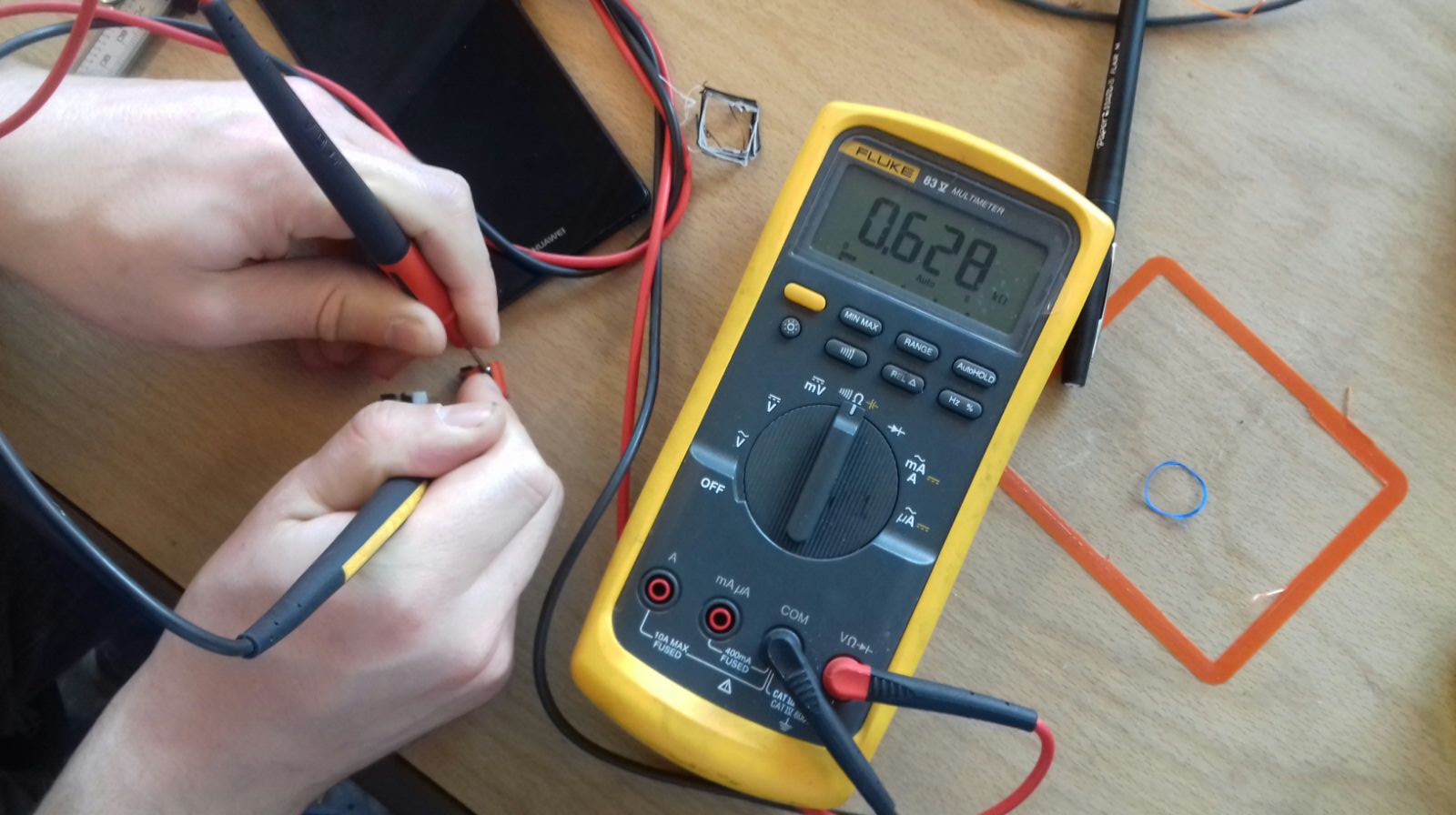
We then decided to investigate this other conductive material from Esun. Which is an ABS.
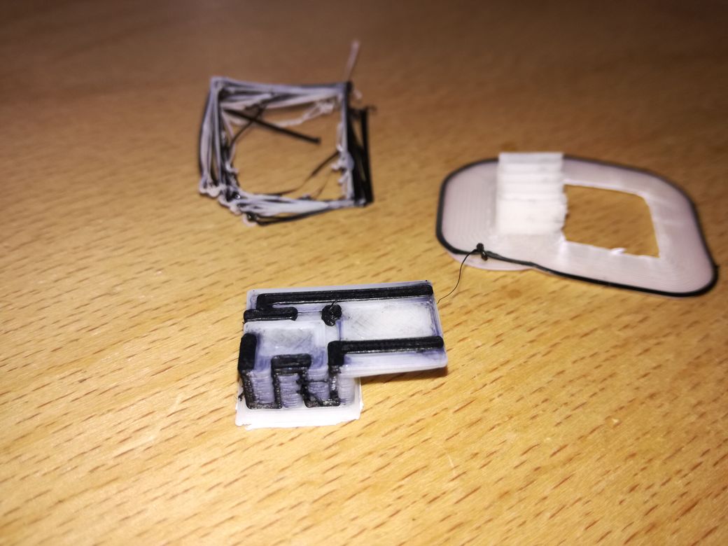
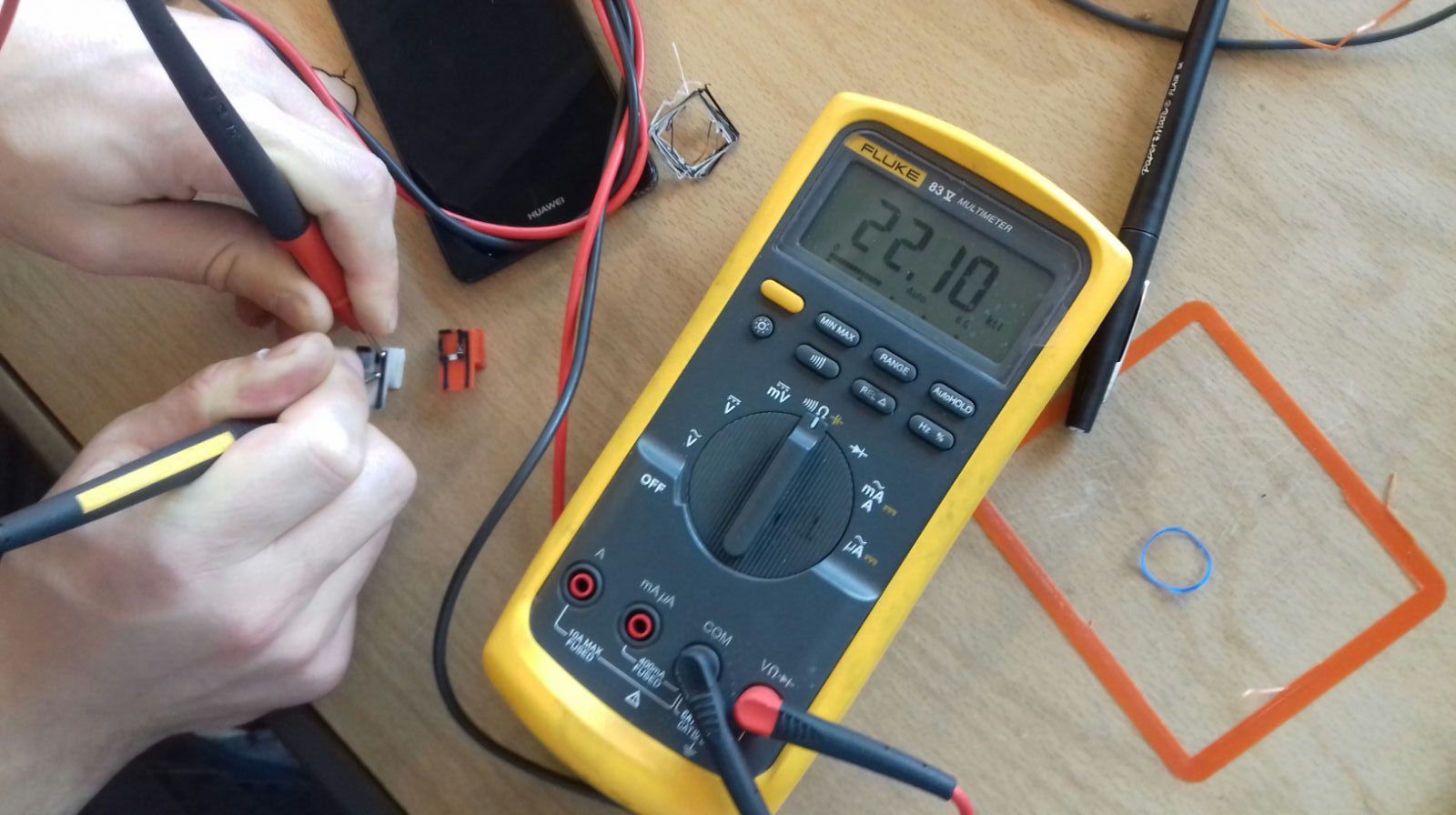
We measure a resistance of 20kOhm/cm on the XY axis; which is way worse than the conductive PLA :/