Machine Design
Fabacademy : Week 15 May 02/2018
Assignement - Mechanical design - schedule
Multiple purpose machin
Links:
3D files : fabRack.f3d
Machin files : machinDesign.f3d
Stocks Materials
- 2 Delrin : 28€ / 500 mm² --> 12mm height
- 1 DHCP : 26€ / 500 mm² --> 10mm height
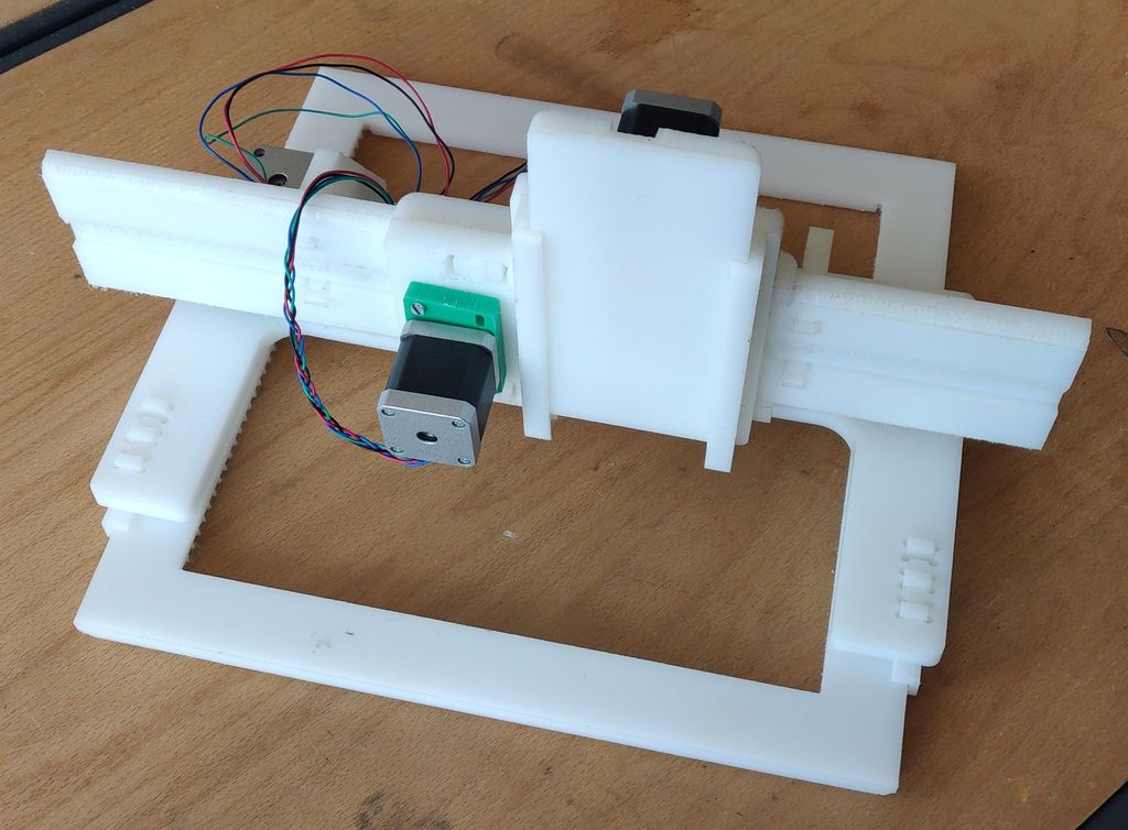
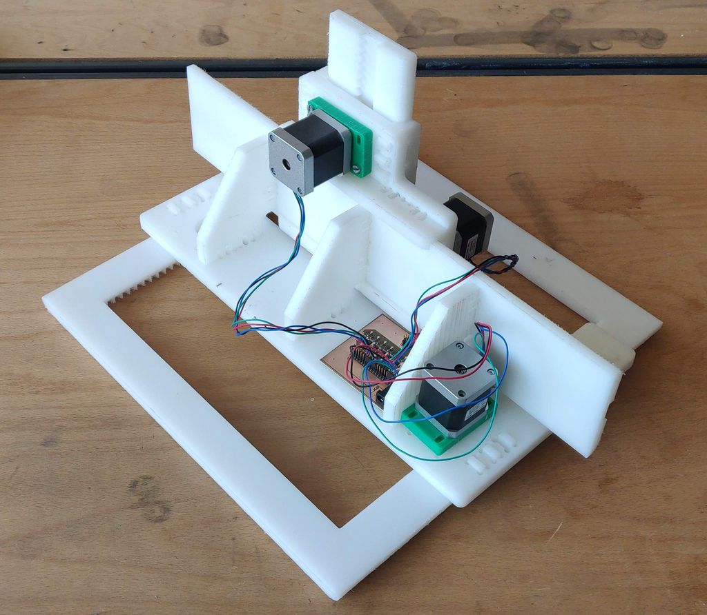
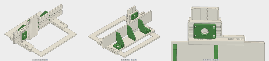
Final Images
| machin Front 1 | machin Front 2 | machin Back |
|---|---|---|
 |
 |
 |
Design thinking :
Process
Inspiration :
To begin with this machin we choose to take two machin as reference. The first one is the one from Hector and the second one came from Nadya.
| Nadia's machin Go to the page |
Jacob's machin Go to the page |
the Chamfer Rail from fellesverkstedet repository |
|---|---|---|
 |
 |
 |
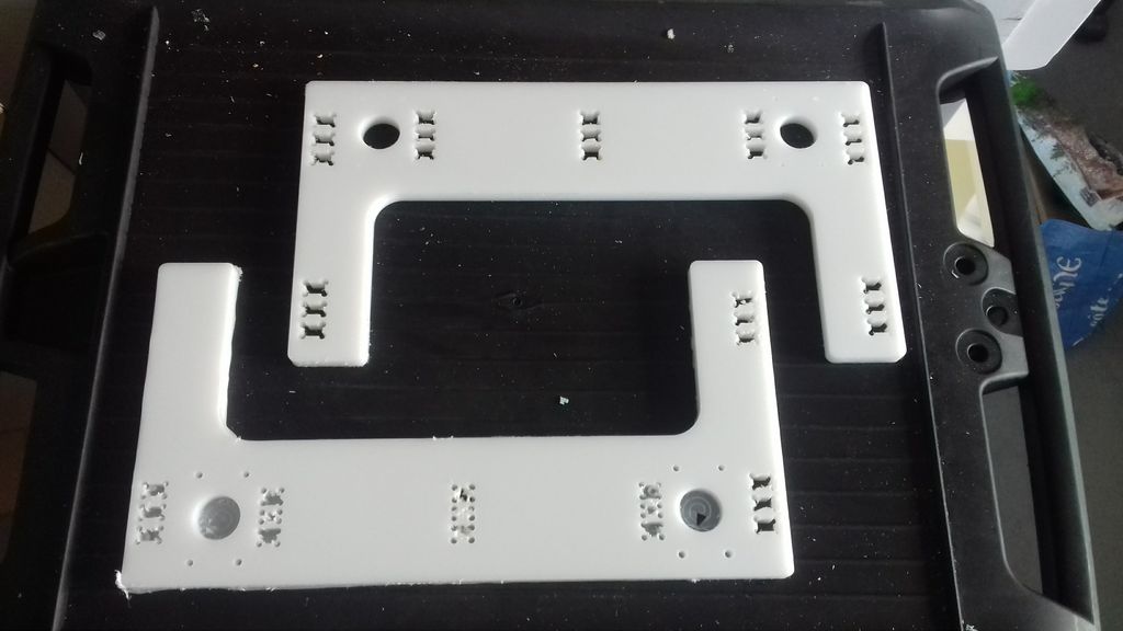
Designing :
The main goal we wanted to succed in making this machin so that anybody who have access to a milling machin could do this. We choose to aboard this design with one main constrain, replace screws by japanese joinery and reduce the necessary supply you need to have for this kind of machine.
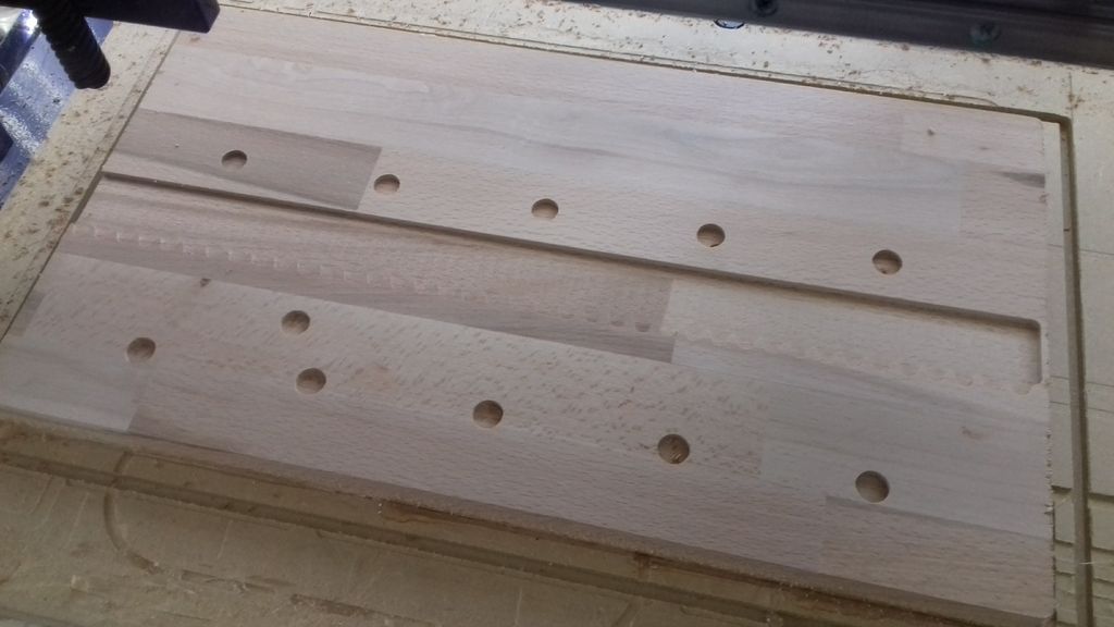
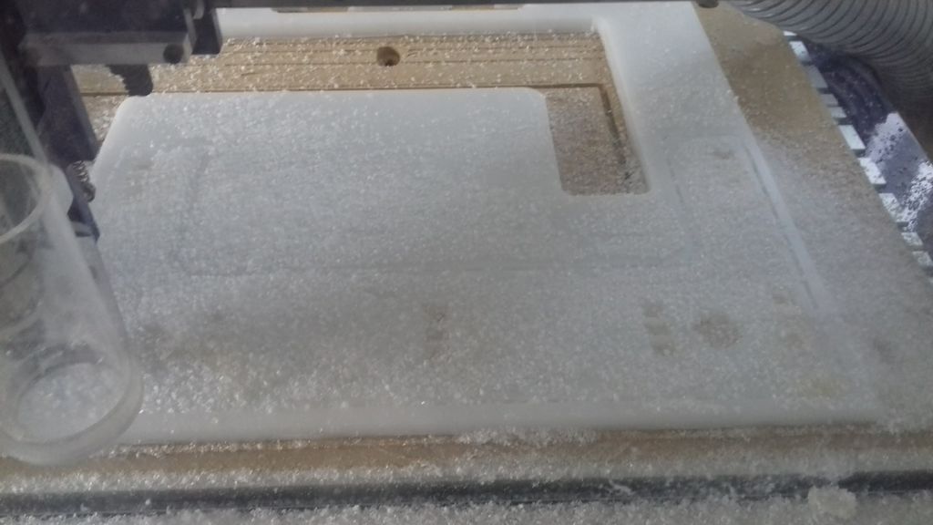
I made wood test to validate the rack format and the faisability on our CNC machin.
|  |
|  |
|---|---|
|
|---|---|
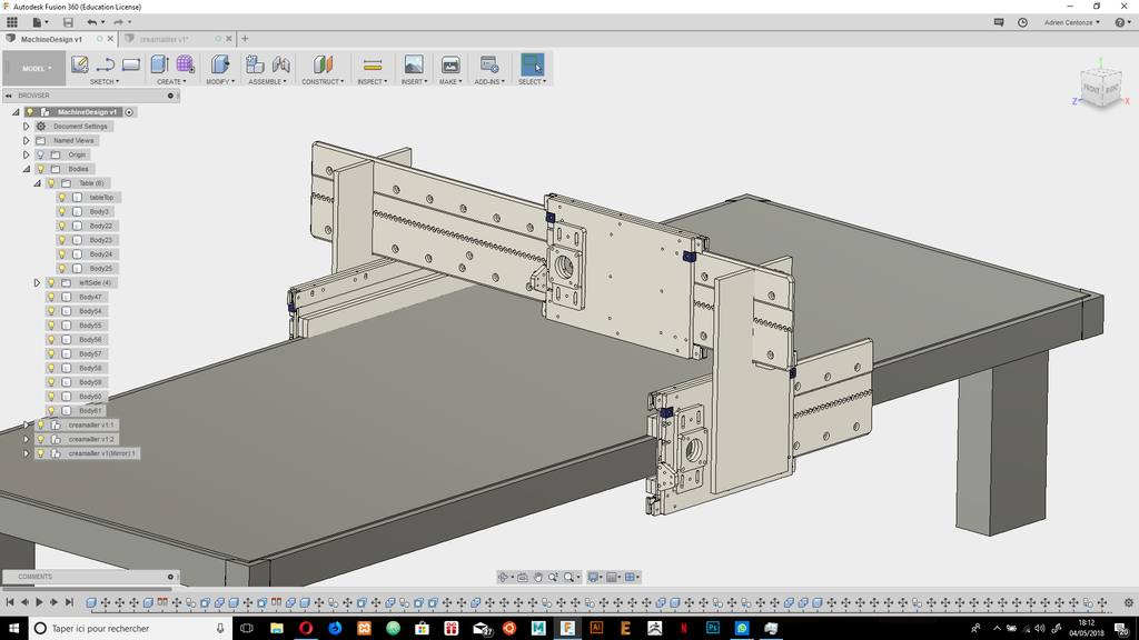
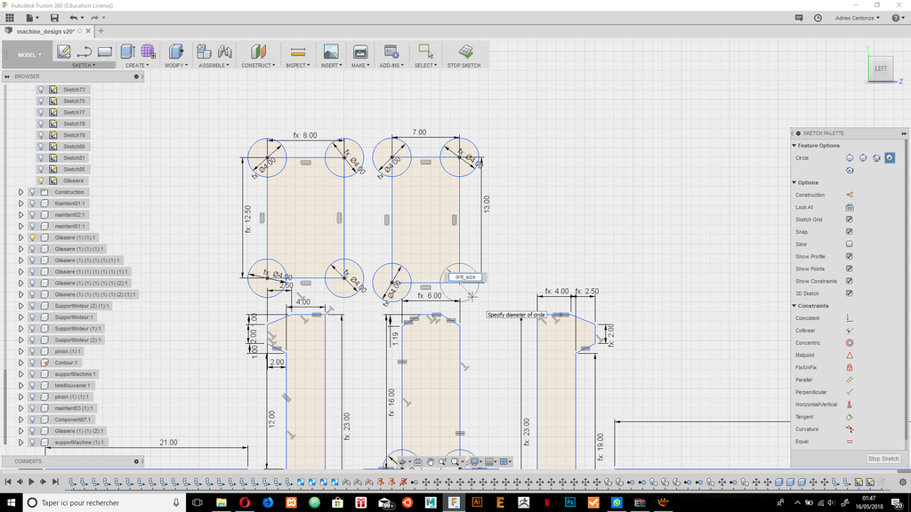
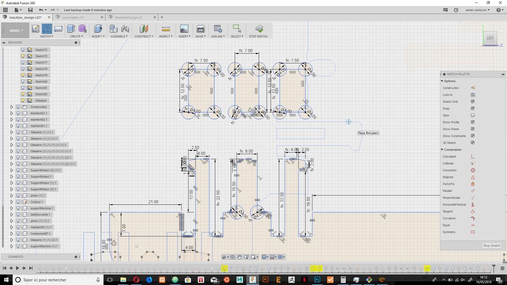
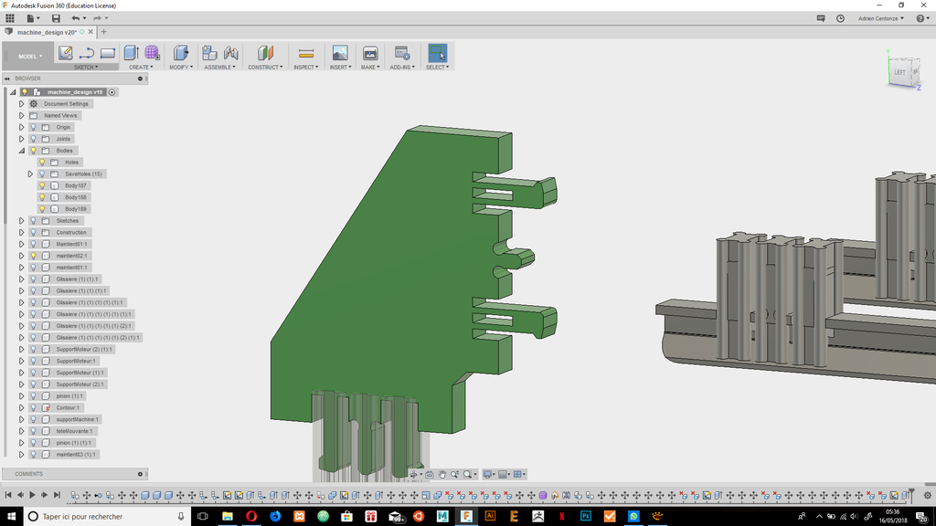
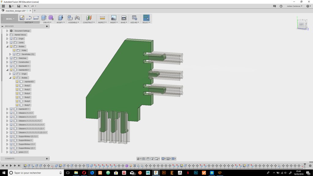
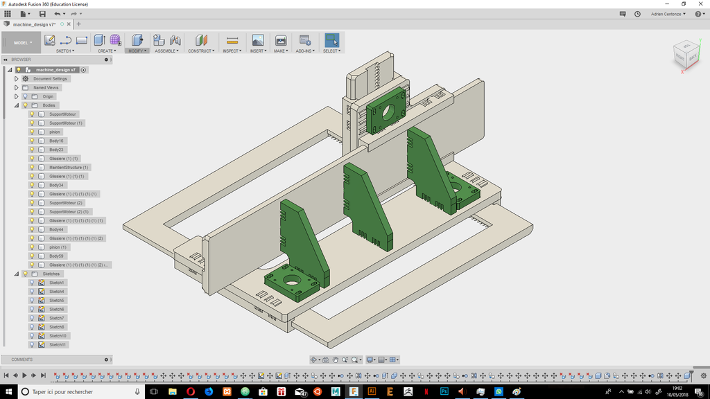
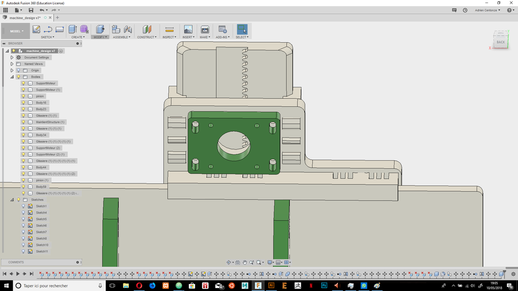
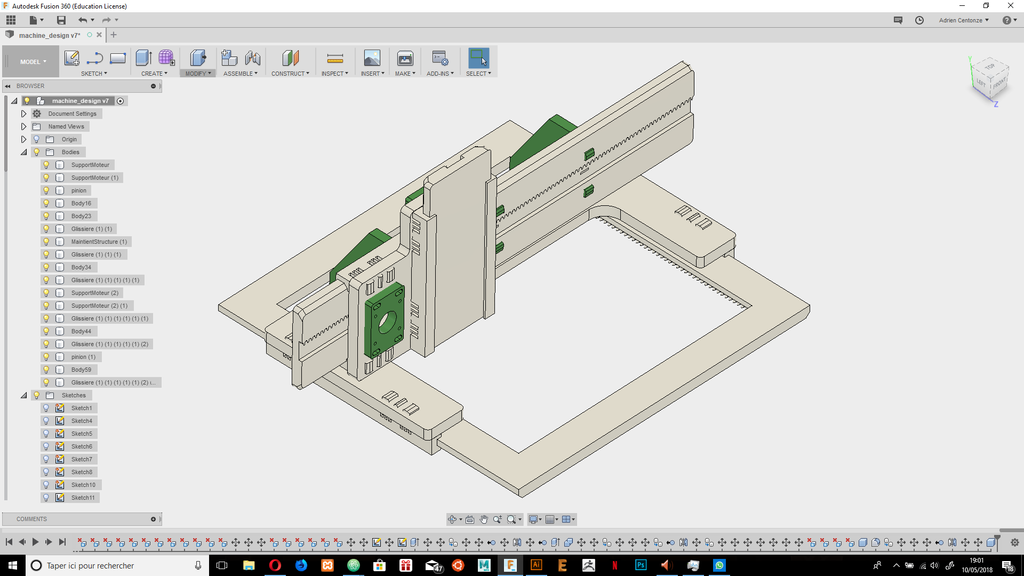
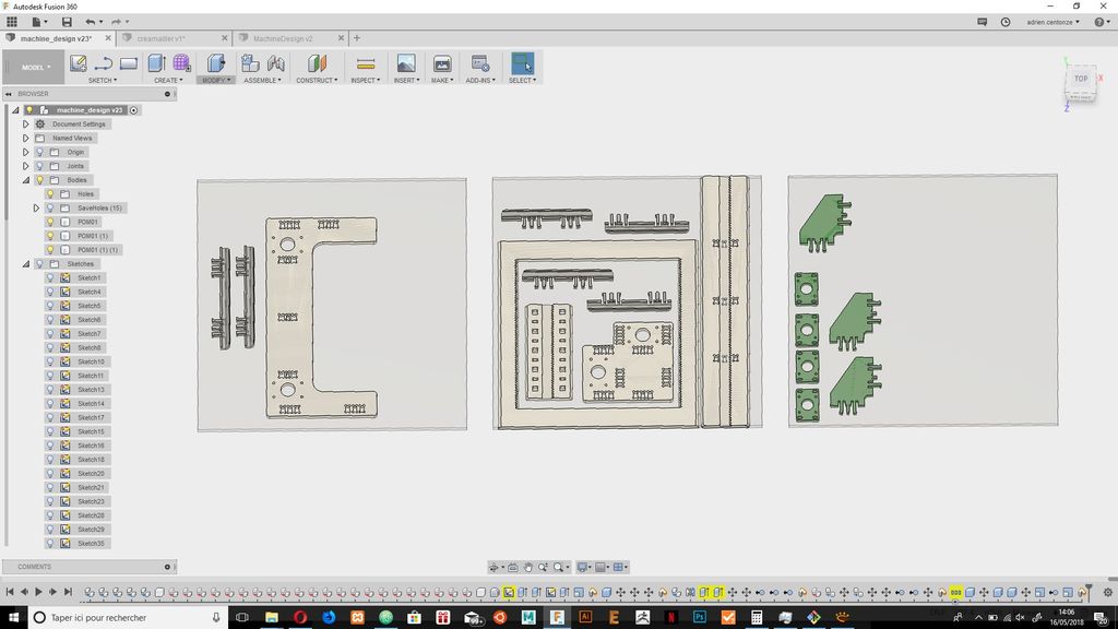
Parametric design
I know that I would have to make a lot of back and forth to succed to make this machin so I worked on making the joinery parametricaly depending on my stock height and my the smaller mill I have that could go that deep.
After working in fusion on parametric joinery
 |
 |
|---|---|
 |
 |
 |
 |
 |
 |
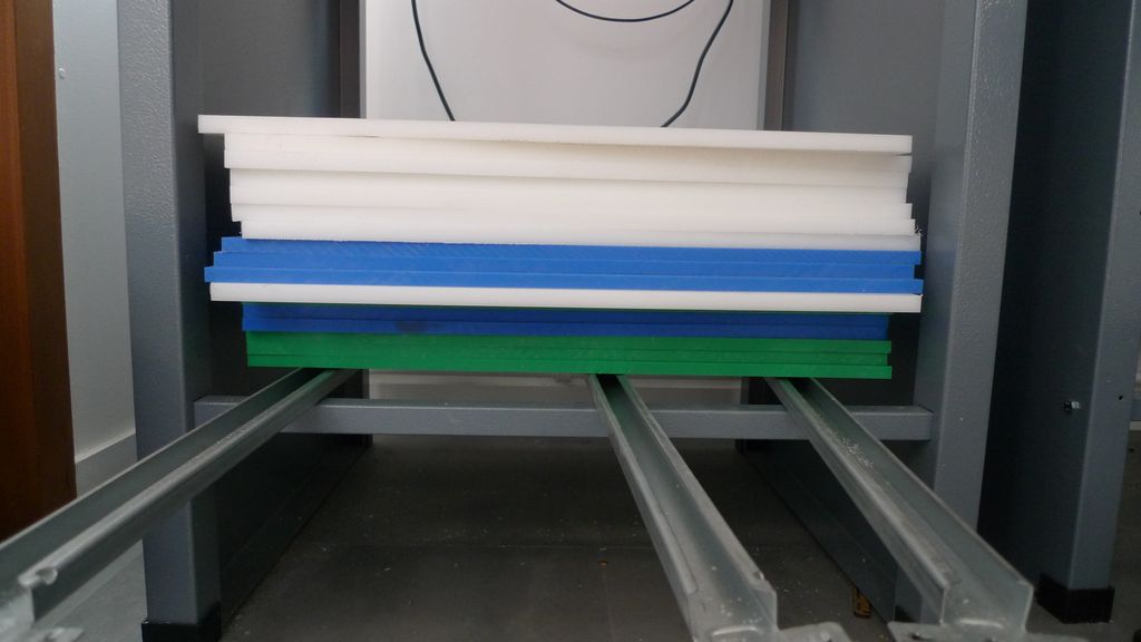
Think about the stock and your machin :
There is two main constrain that you couldn't avoid when doing a machin like that it's your stock, what size and weight is it.
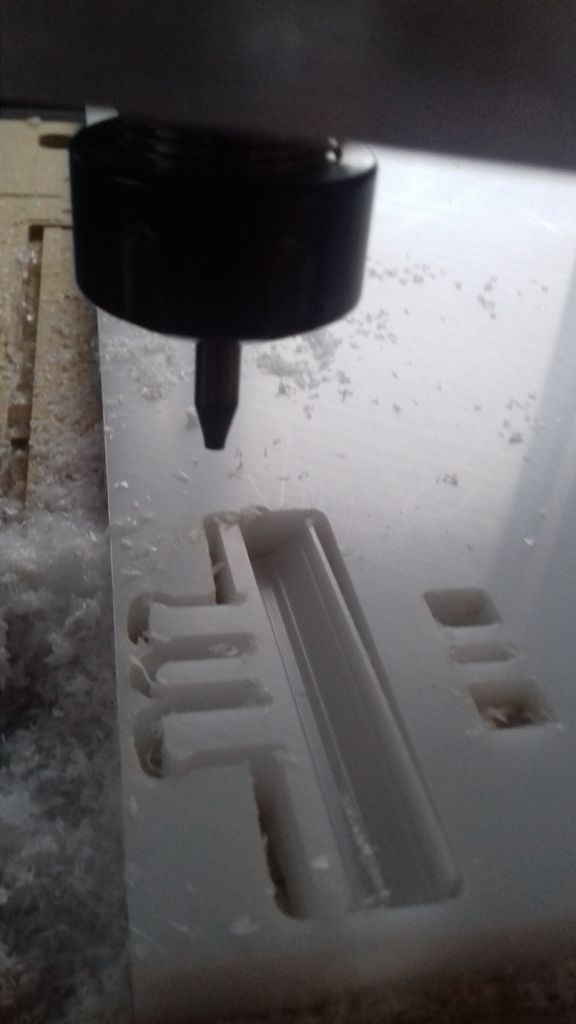
milling prototyping
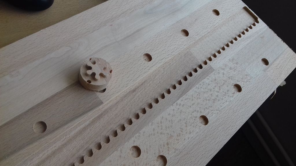
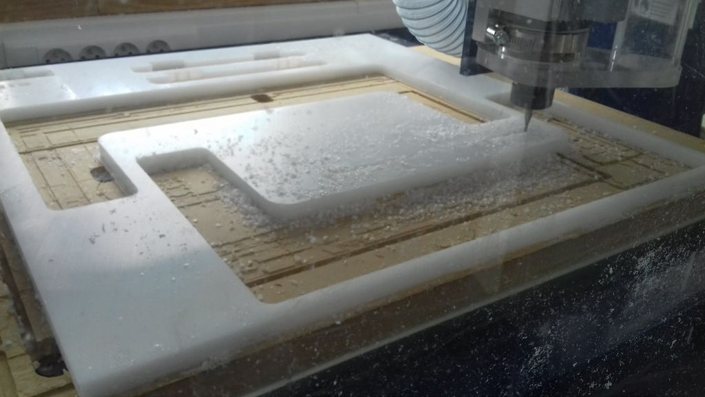
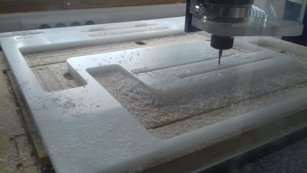
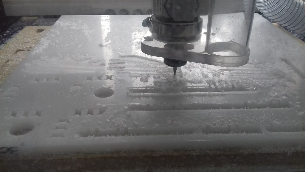
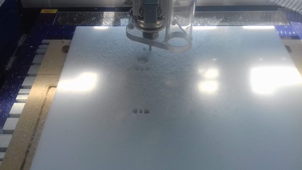
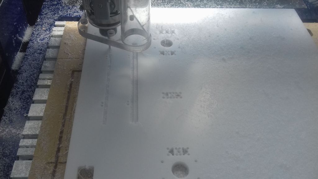
In order to know more about rack and pinion, I made a first rack and minino with a junk of wood we had here in the lab.
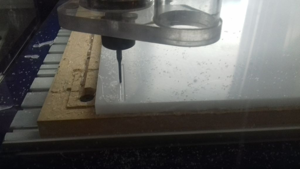
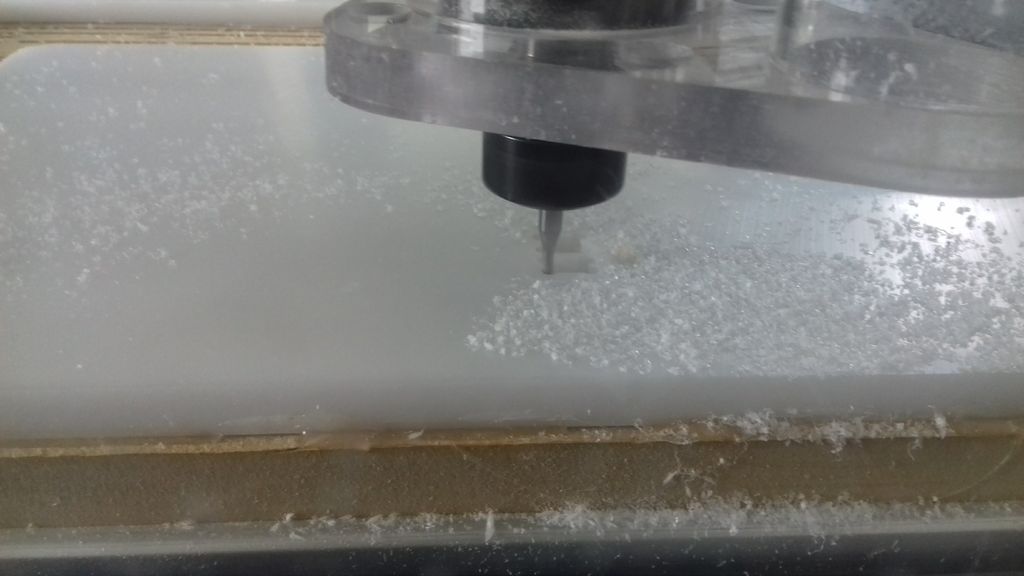
Then I wanted to be sure of the joinery I made, so I made a simple milling test on our shopbot.
 |
 |
|---|---|
 |
 |
 |
 |
 |
 |
 |
 |
 |
 |
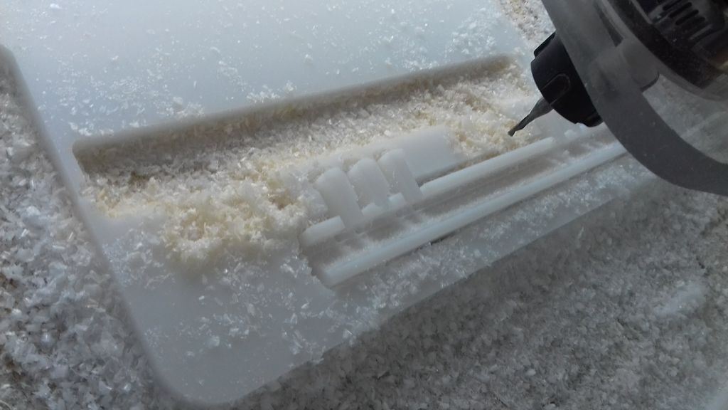
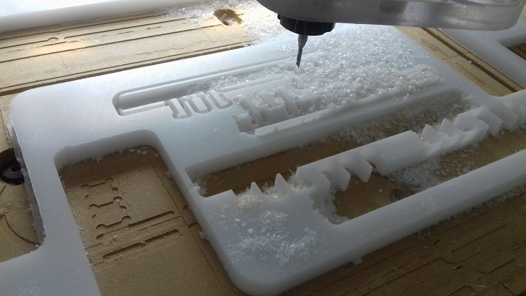
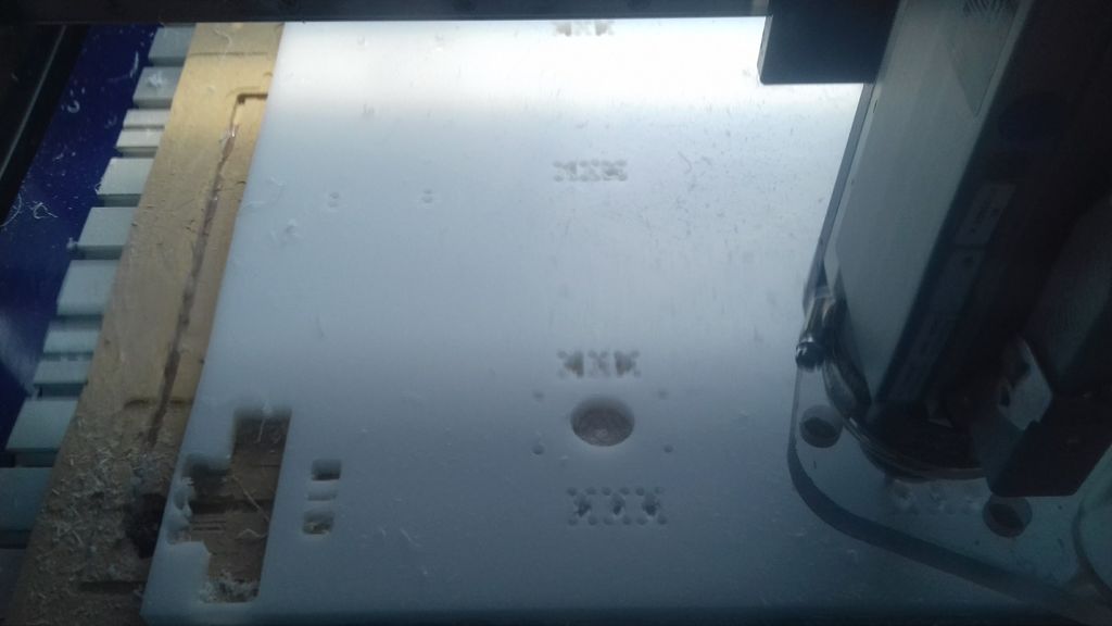
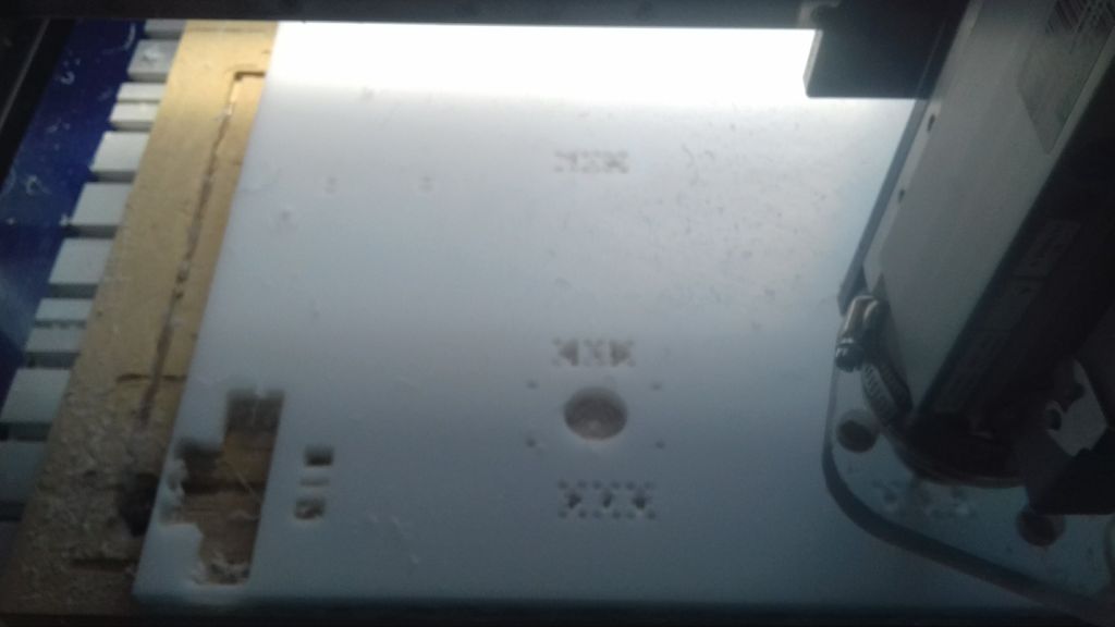
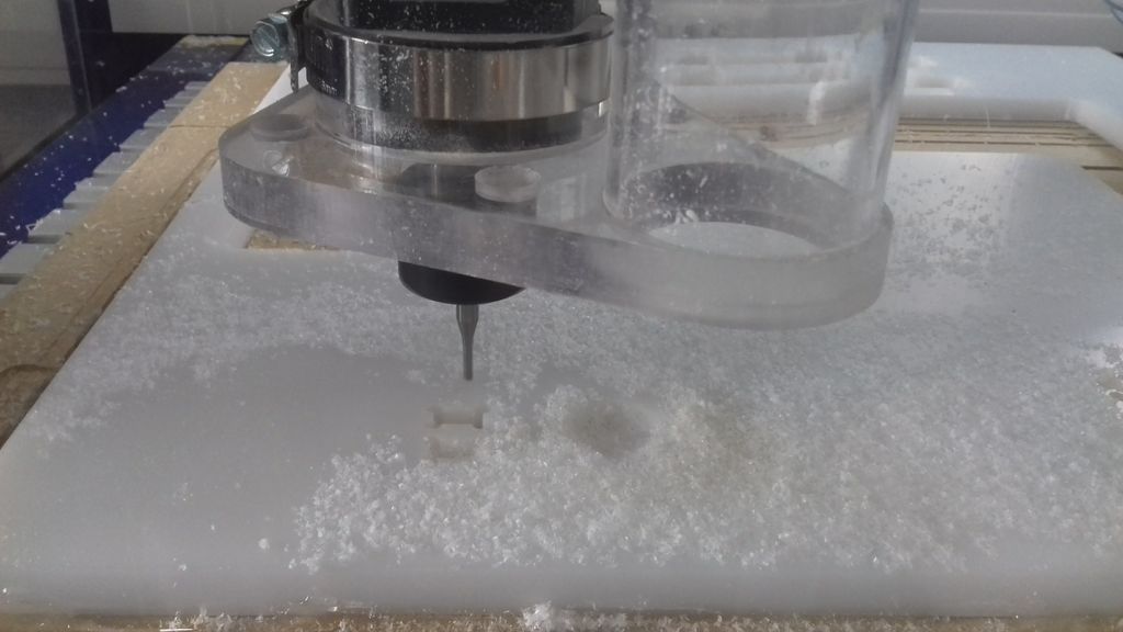
On the testing phase, I break a ballnose mill cause I didn't made my pads high enough.
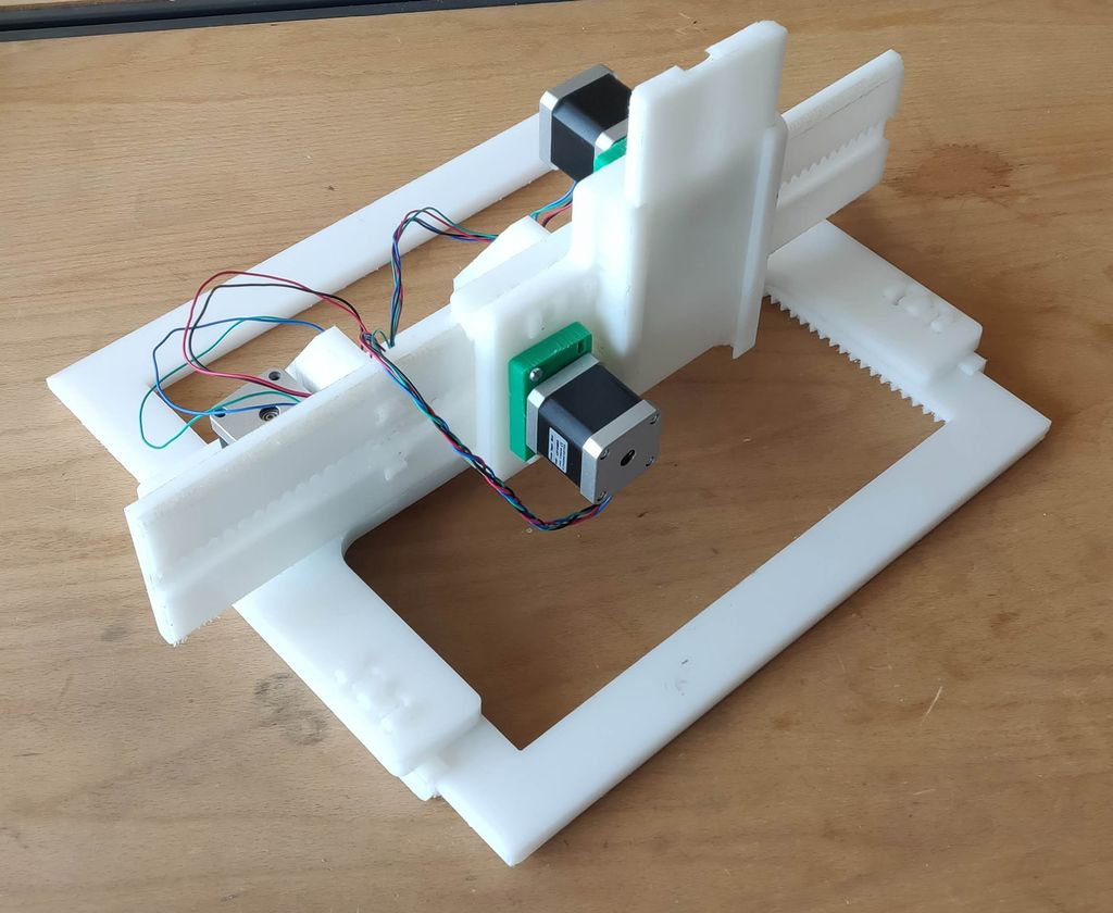
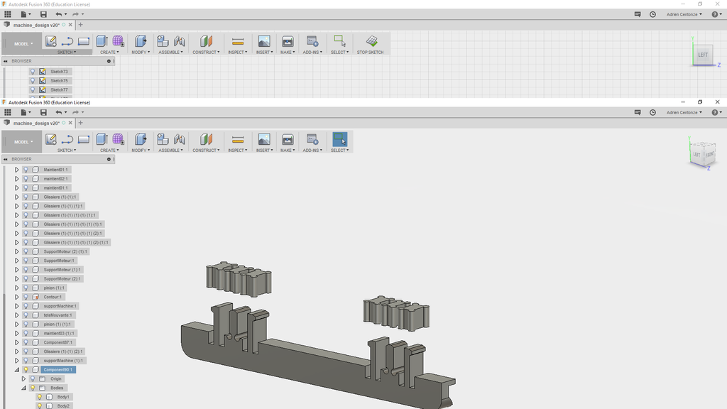
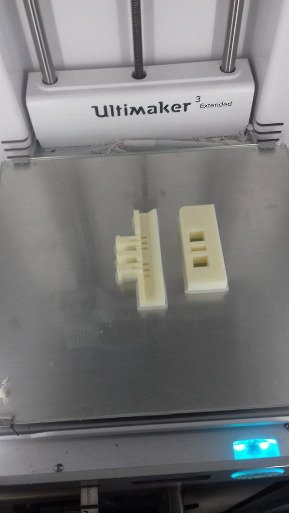
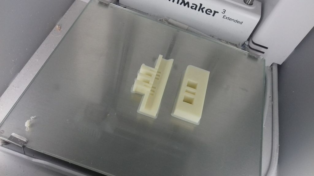
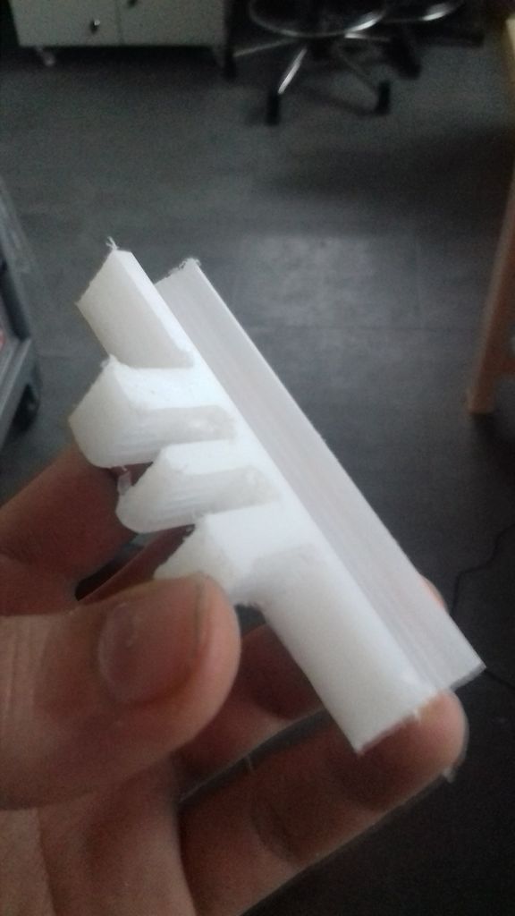
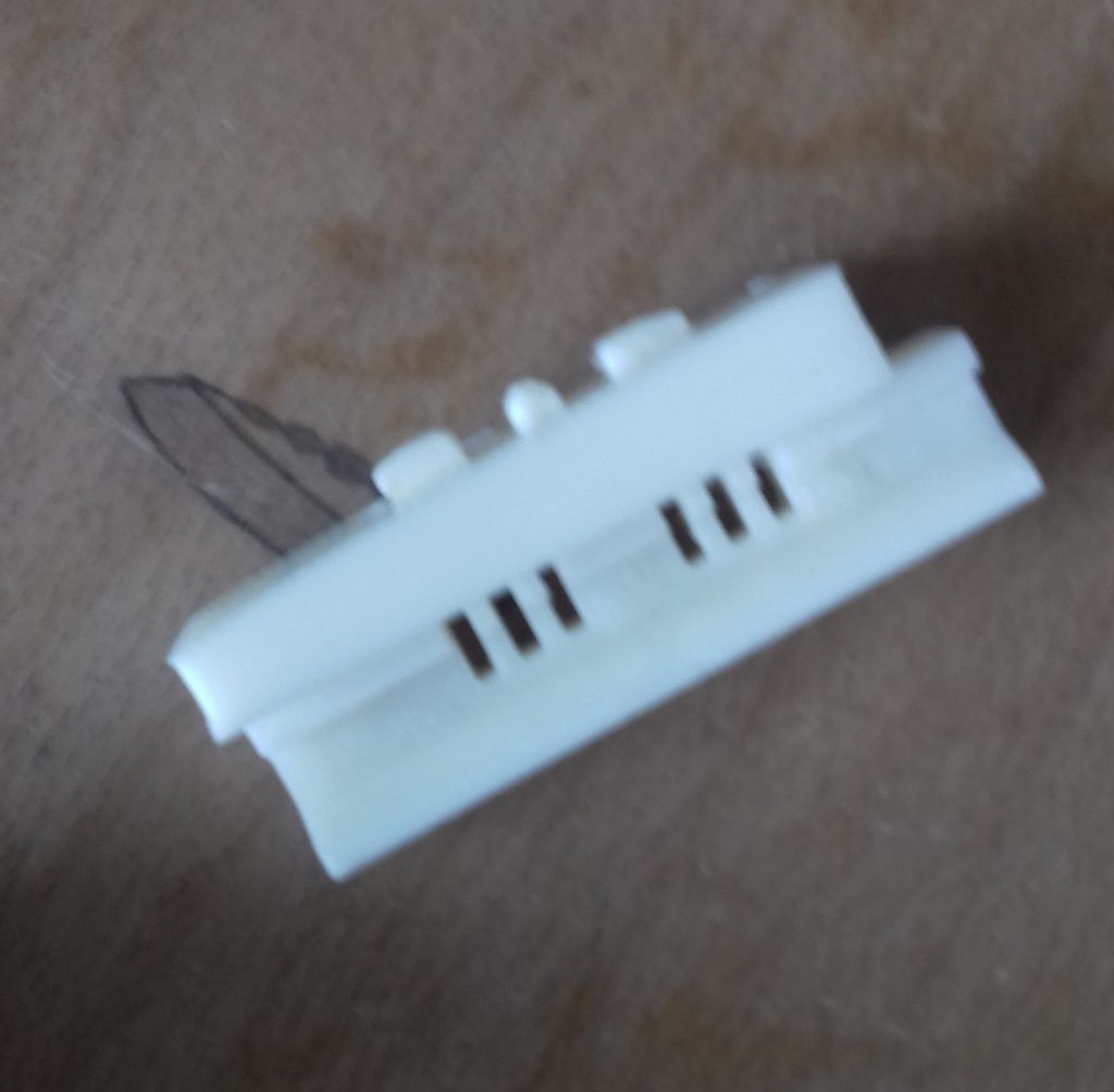
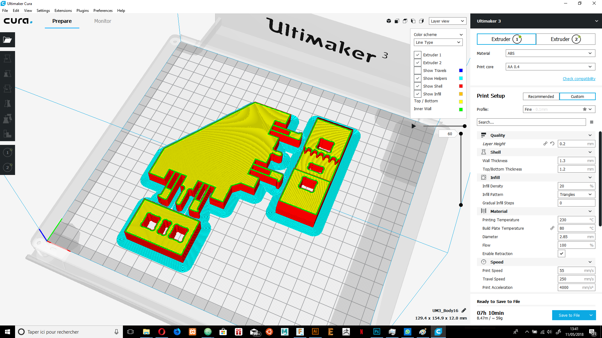
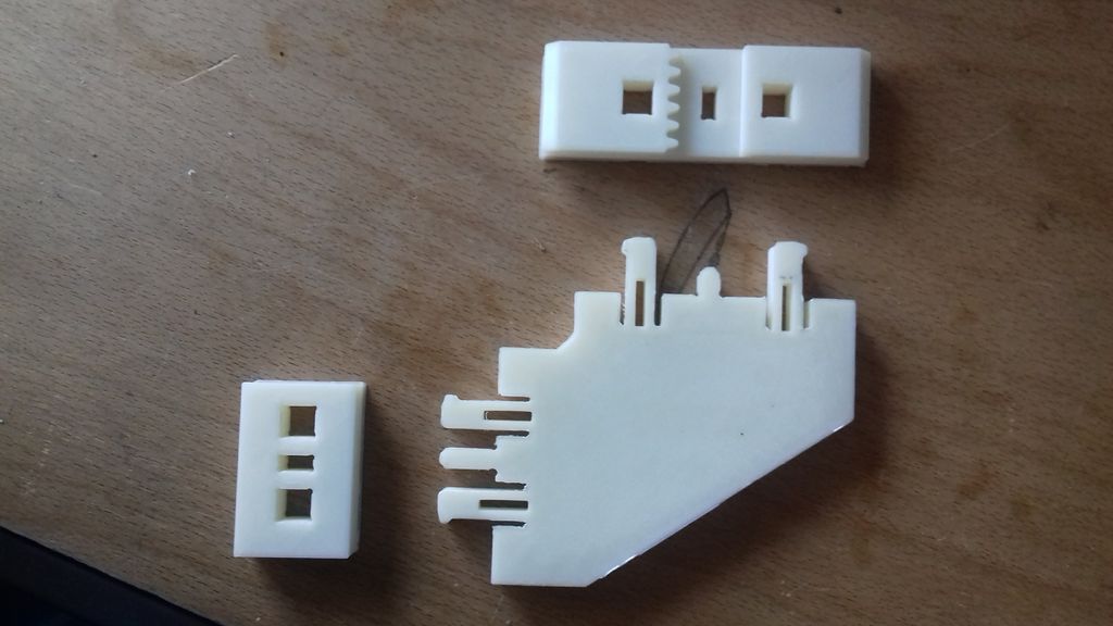
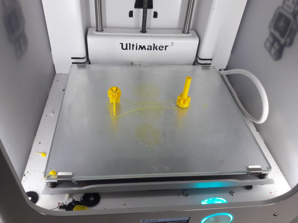
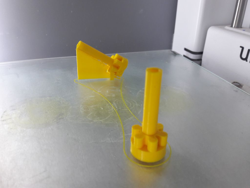
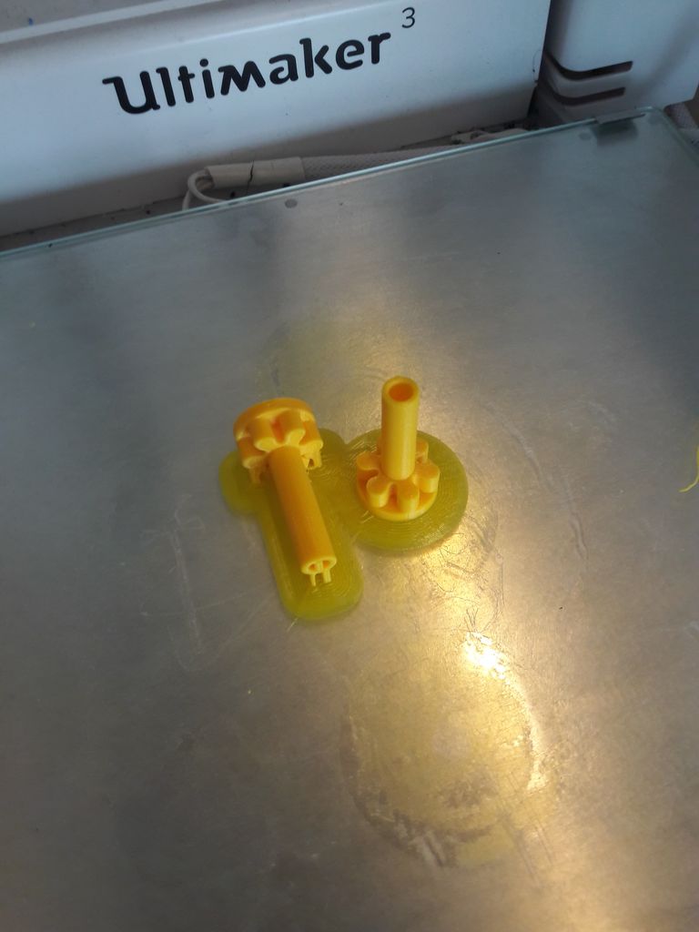
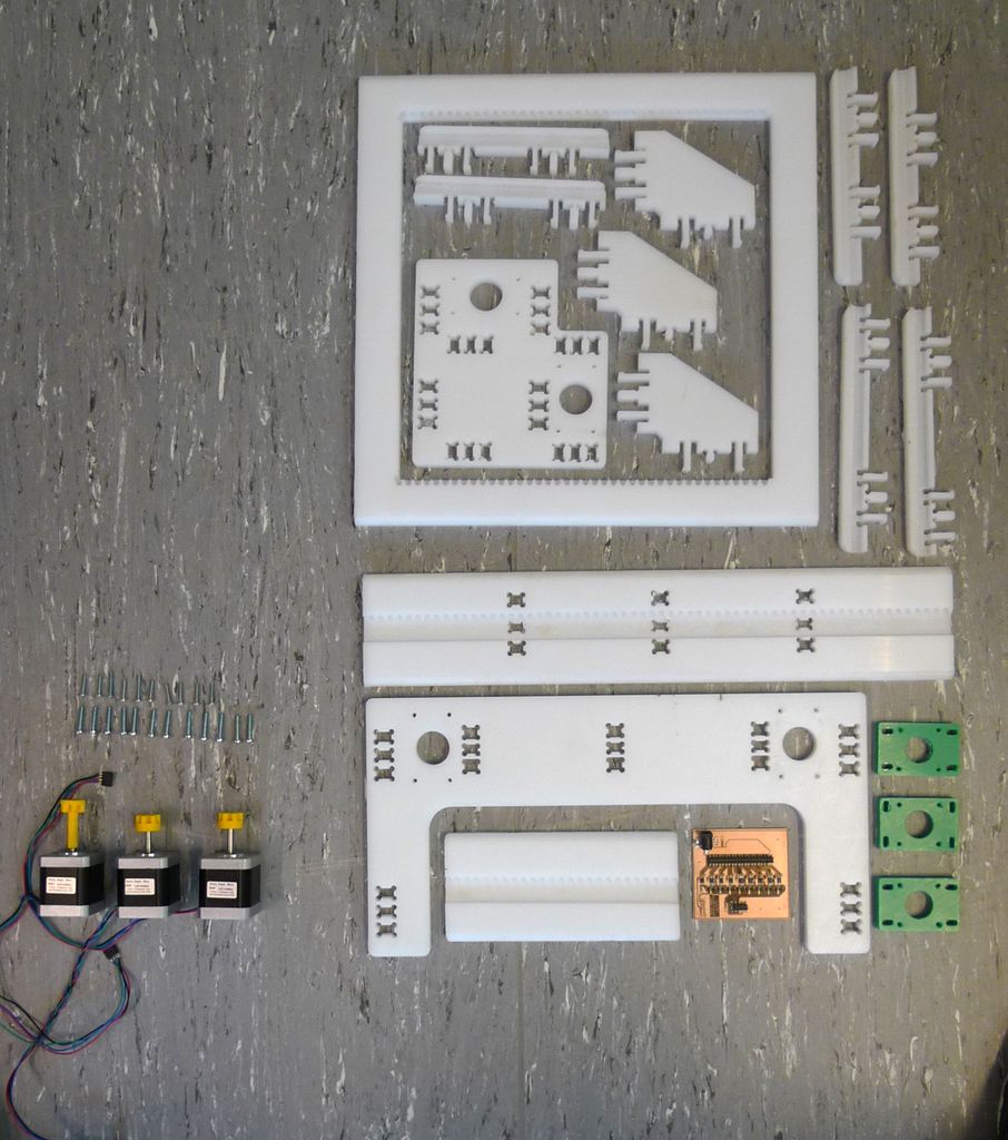
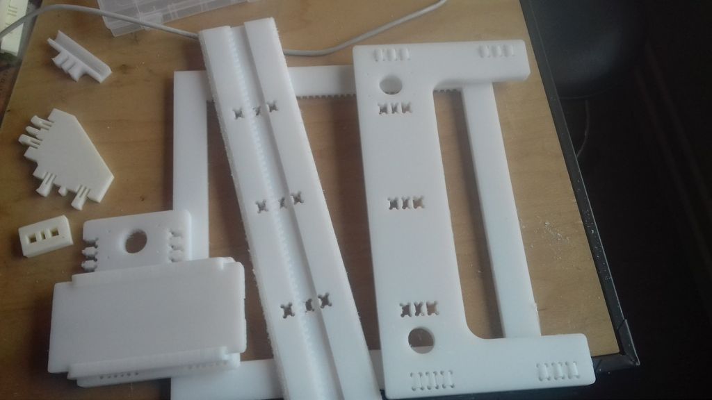
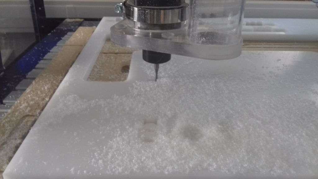
3D prototyping
To be sure about the join I used I made some rapid prototyping with the milling machin first, and then with the 3D printer.
 |
 |
|---|---|
 |
 |
 |
 |
 |
Montage
 |
 |
 |
|---|---|---|
Stock comparison, from the store to the lab
In every design process, there is junk generated by your creative process that could be more or less important du to complexity of what you are trying to do. Here is everything we tryed and fale to do this machin.
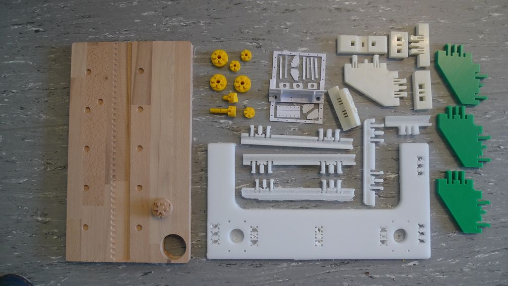
And here is the comparison of our product. On the left everything we didn't made ourselves, and on the right, what we made in the fablab, including electronics.
Milling :
Preparation
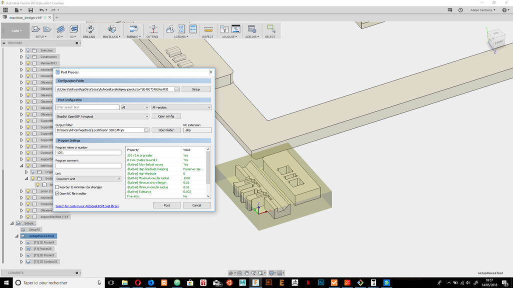
Toolpaths
Parrallel 3D
!
2D Pocket
 |
 |
|---|---|
 |
 |
 |
 |
 |