Electronics Production
This week I made an ISP - an "In-System Programmer" - specifically an ISP for AVR microcontrollers. This ISP will be used in upcoming weeks to program other boards that we will design and build. I started out following a tutorial that provided PNG files for the board's traces and perimeter as well as a list of electronic parts to be soldered on the board.
To get started, I used MODS to process the PNG files and send them to the Roland SRM-20 milling machine. I tried to use MODS in Windows to speak to the Roland, but the Print Server insisted on throwing an error that I couldn't figure out. After booting the machine to Ubuntu, I was able to successfully communicate to the machine.
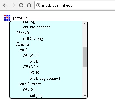
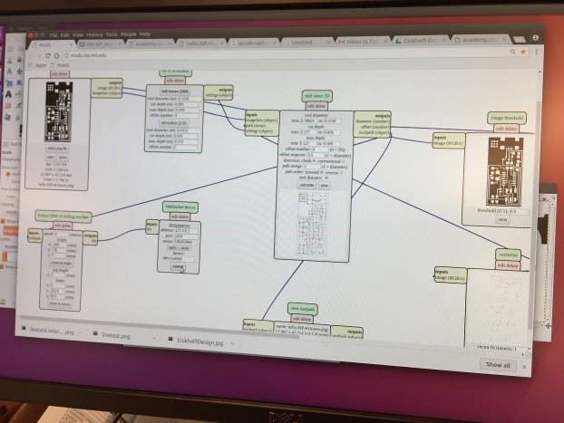
I started the MODS interface and chose to run the "Roland SRM-20" server program.
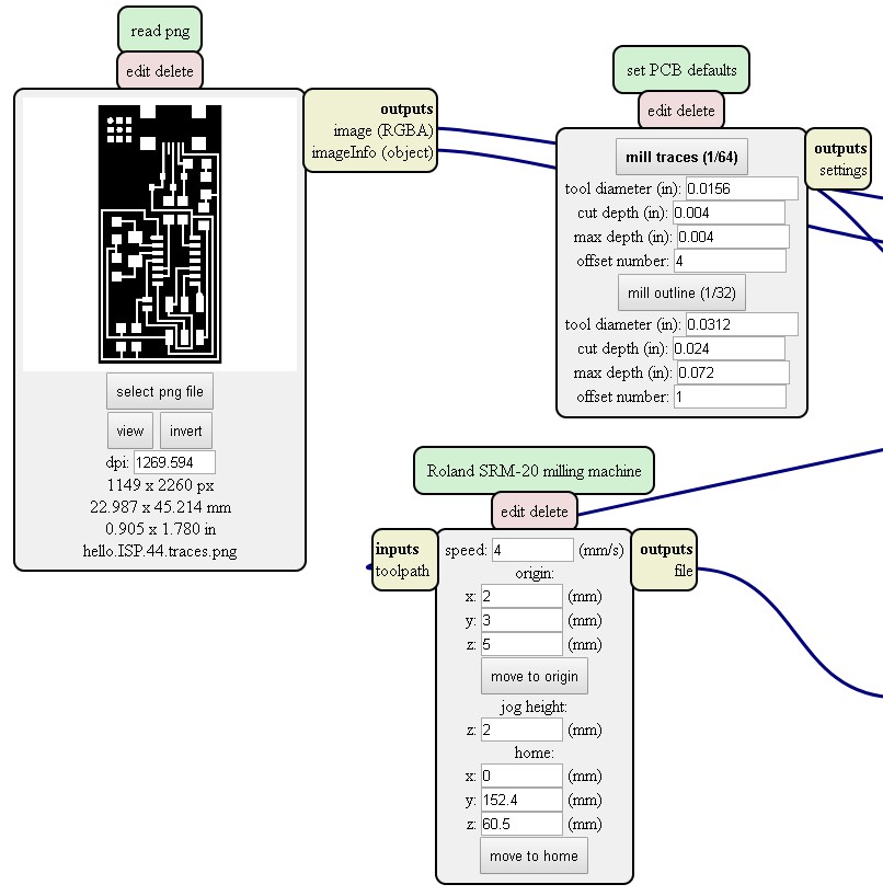
Then I imported the PNG file for the traces and selected the "mill traces 1/64" button in the "set PCB defaults" module. The default values worked fine, but I learned that these are the numbers you'd want to modify if, for example, the bit didn't cut deep enough to remove all of the copper.
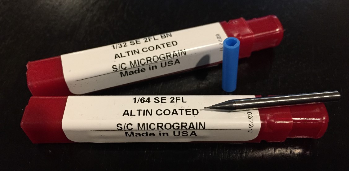
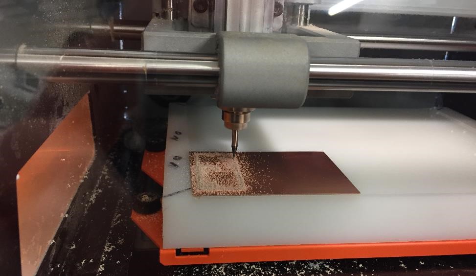
Speaking of bits... There are two different bits that I used to mill the board. The first was the 1/64" bit. It was used to mill the traces. Then I used a 1/32" bit to machine the perimeter and free the board from the larger stock.
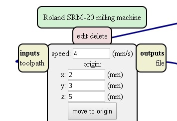
With the bit in place, I could set the zero location of my bit. I used the MODS interface to move the bit close to the near-side, left hand corner of my copper-plated stock, and then loosened the collet on the mill so the bit would drop into contact with the board. Holding the bit in place, I retightened the collet.
In the MODS interface, I clicked the "Calculate" button followed by the "Send to Printer" button...
...and cut my first board!
To reinforce my newly acquired skills, and to have a bit more fun using MODS and the Roland, I decided to design my own board! I started pushing pixels around in MS Paint...
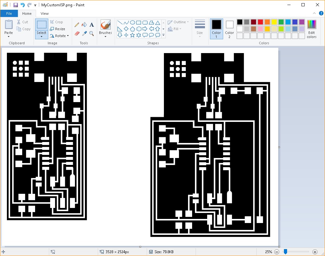
...but that proved to be too tedious.
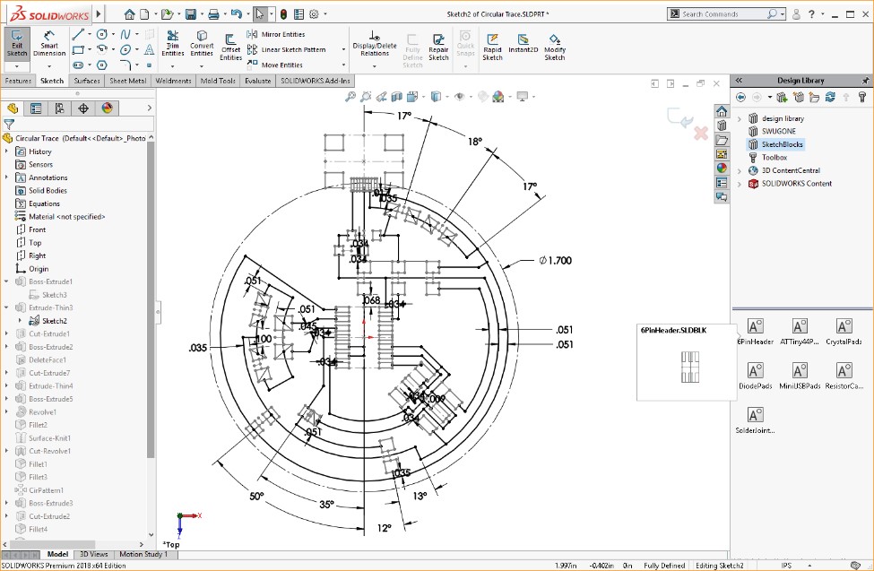
As I then considered taking up the challenge that Bas announced at the end of class, I turned my attention to SolidWorks to help me design a circular board!
First, I used calipers to measure the pads for the various components on the board. Then I created a SolidWorks Block file for each of the components - the AATiny44, the Resistors, the Diodes, etc. This will make designing future boards much easier as I'll be able to simply drag each block into my sketch and position it where I like.
I did all of my component and trace layout in one sketch - something I would normally avoid in the interest of keeping things simple, but it worked out just fine. I was able to leverage parametric relations to ensure the sketch behaved the way I wanted.
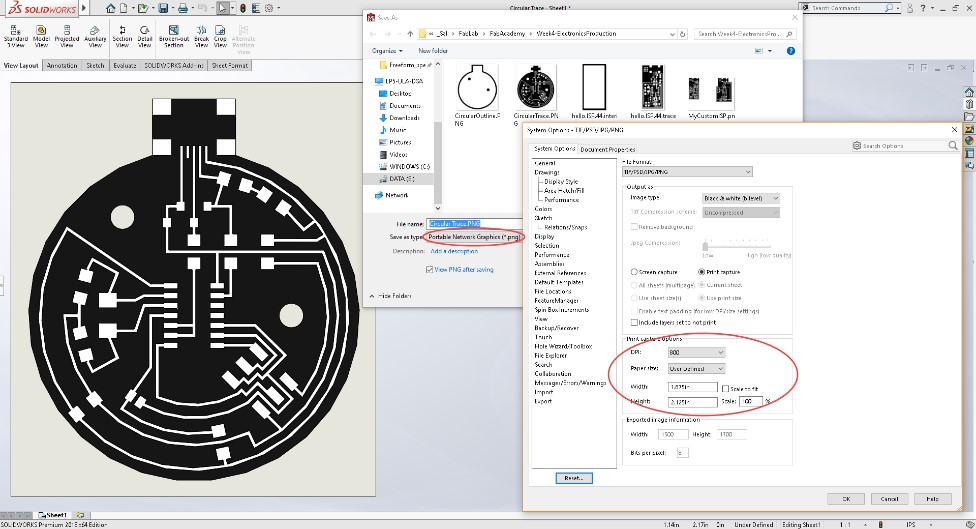
I extruded a base shape of the outline, and then I extruded the pads and traces. I kept the extrude depths realistic, but ultimately it didn't matter, because I next created a SolidWorks Drawing of the Top view and subsequently saved it as a PNG. I bumped the DPI up to 800 and made sure the PNG paper size matched the custom drawing sheet size that I used. I learned that if you don't do this, the PNG will scale when you open it in MODS and you run the risk of cutting a board that doesn't match the size you expected.
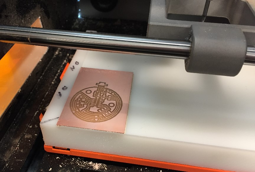
I created a complimentary PNG that described the perimeter and clearance holes (I'll later use these to mount this board to a housing I plan on 3D Printing), and then ran both PNGs through MODS to produce my custom board!
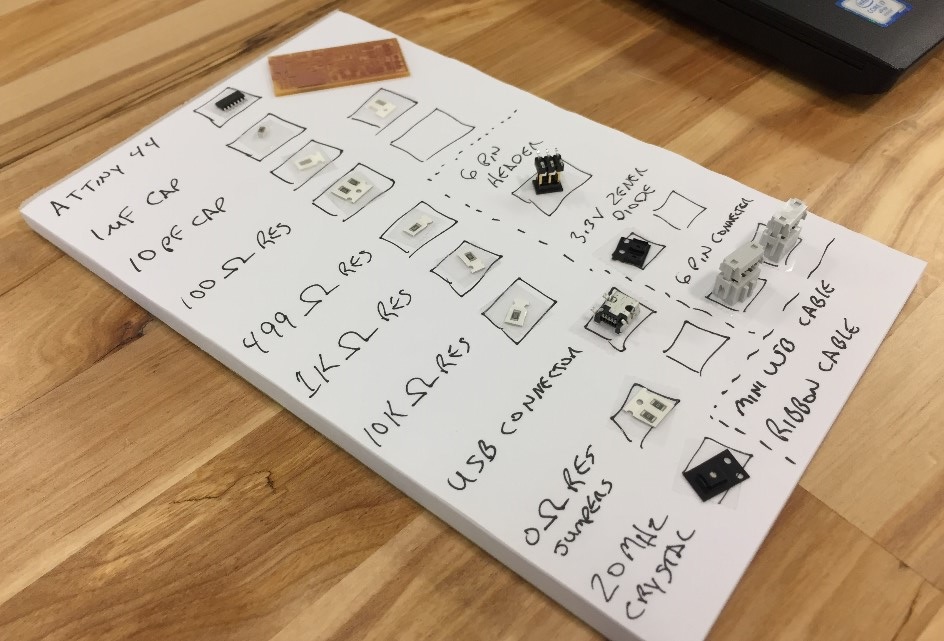
With the board cut, I turned my attention to stuffing it with all of the components. I borrowed a great idea from a classmate and used double-sided tape to adhere the tiny parts to a handmade visual Bill of Materials.
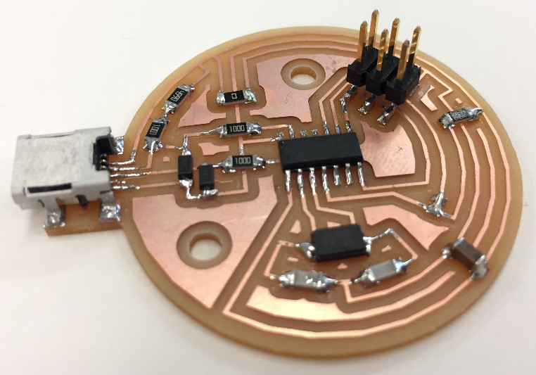
Then I tried my hand at soldering things in place. It was slow going, but I am pleased with the quality of my solder joints. The tips that Neil gave during class about how to watch for the solder to start to flow and then be patient as it forms a nice smooth slope between the component and the pad really helped me aim for a nicely finished product.
I rounded out the project by programming my board. I followed all of the steps outlined in the tutorial, but found that this particular task is not well suited for a Windows PC :(
The necessary WinAVR software has been abandoned, and although I worked through installing the old application, installing the Windows Adafruit Drivers and the FabISP Firmware, and editing the Makefile, I still ran into errors running the "make fuse" command. The only way I found around the issue was to use a classmate's Mac to program my board using an Arduino. Thanks Greg!
I plugged my board into Greg's MAC using my miniUSB cable, and then joined my board to Greg's recently programmed ISP, also connected to his MAC.
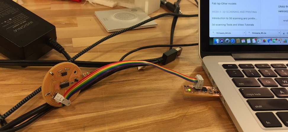
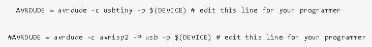
I made sure the MakeFile was properly edited to indicate that I was using another ISP to program my board. To do this, I simply uncommented the "usbtiny" line in the MakeFile and commented out the "avrisp2" line.
Then I used the "make fuse" command to set the fuses on my board so it will use the external 20MHz crystal as its clock.
Finally, I programmed the board using the "make program" command.
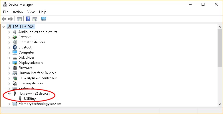
Each of these commands ran successfully, so I just needed to verify that my ISP was in fact an ISP. I unhooked it from Greg's MAC, and plugged it into my Windows machine using the miniUSB cable. I opened the Windows Device Manager and - ta-da! - there it was!
So that my ISP could no longer be programmed, and would always act as an ISP, I removed the solder jumper from my board. Finally, I worked with another classmate to use my programmer to program her board. Again, we used a Mac to do the job!