Output Devices
Building on last week's "input" assignment, I turned my attention to the RGB LED that I added to my Hall Effect sensor board. My goal was to program the LED to change color in response to the presence and magnitude of a magnetic field.
To recap my PCB design process... I started by looking at the sample RGB LED board on the FabAcademy Output Devices page. It helped me understand the basic workings of the board, so I could incorporate an RGB LED into a board along with an Hall Effect sensor. To accommodate both devices, I had to "upgrade" the microcontroller to an ATtiny44 as it offered enough I/O pins.
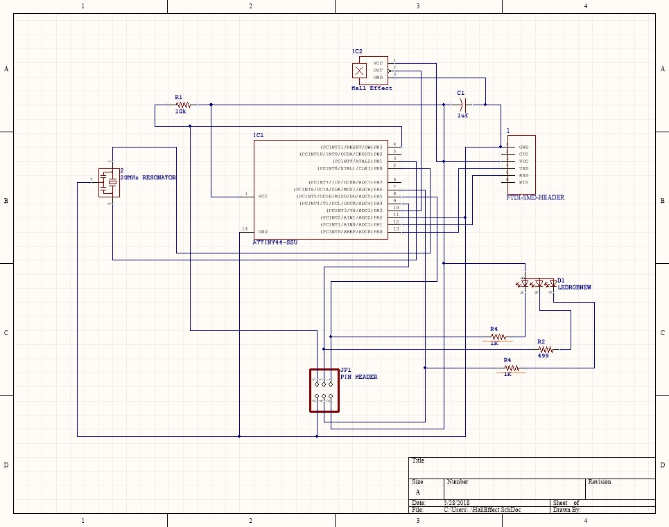
I then drew a schematic of the board using SolidWorks PCB.
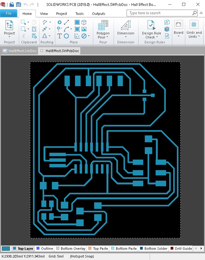
Next, I laid out the components and traces on the PCB.
Once I had the traces all laid out, I exported them as a Parasolid file so I could open them in SolidWorks and process them a bit further. I changed the color of the board to white and the color of the traces to black. Then I created a 1:1 scale drawing of the board on a drawing sheet that I custom sized to 2" x 3" to match the size of my physical copper plated board.
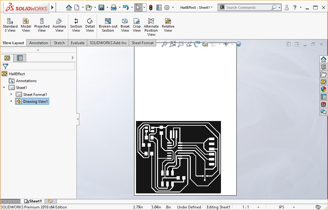
I saved the drawing as a PNG file and opened it in MODS so I could send the job to the Roland Precision mill.
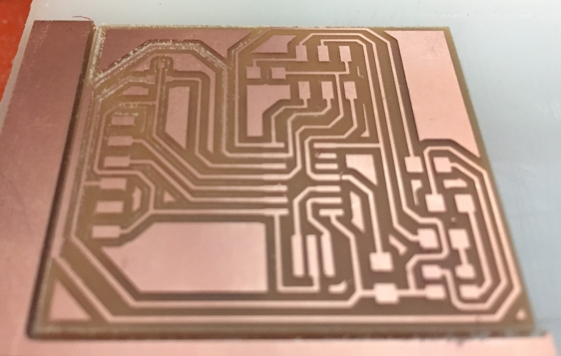
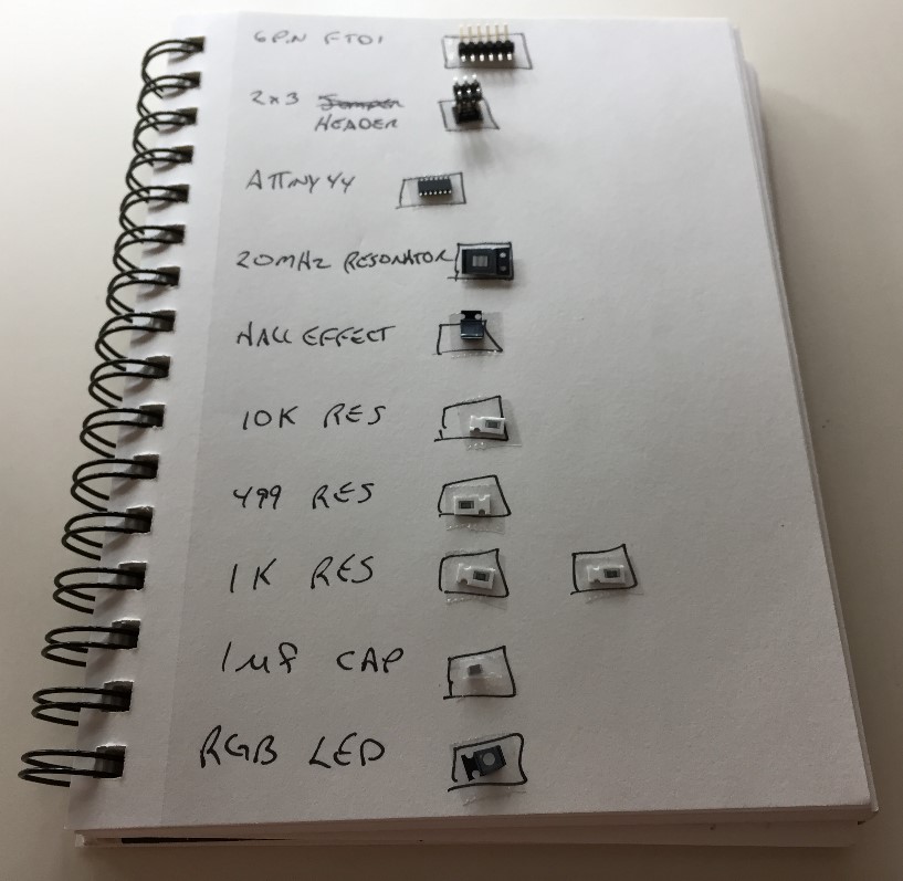
I wrote my Bill of Materials in my notebook and used double-sided tape to hold the parts in place while I gathered them.
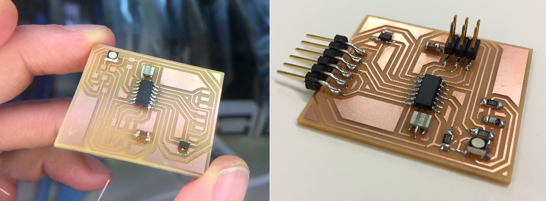
Then I soldered the components in place.
I started the Arduino IDE and began writing code to light my LED. I did a quick search for a sample from which I could learn and found a nice example by Dejan Nedelkovski on the "How to Mechatronics" site. Not only did this code give me the guidance I needed, but it also showed me the syntax for writing a simple sub-routine into which I could pass variables and have it execute actions.
I adapted this code for my needs, placing the appropraite sub-routine calls into conditional statements I created depending on the value returned by my Hall Effect sensor.
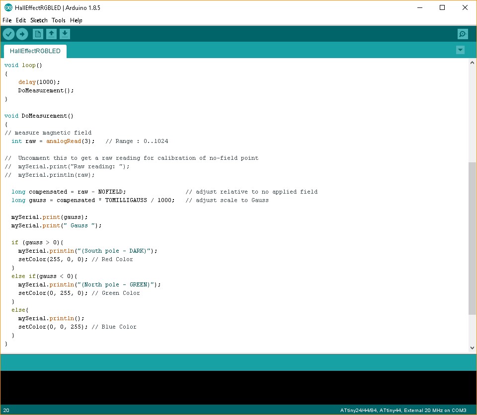
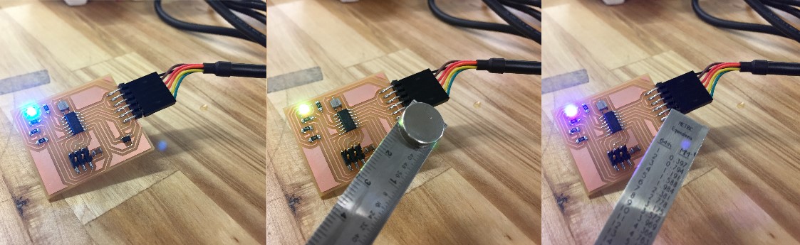
In short, my code lights the LED Blue when it detects no magnetic field, Green when it detects the south pole of a magnetic field, and Red when it detects the north pole of a magnetic field!
Thankfully, I didn't run into any trouble with this assignment. I was curious, however, about decreasing the brightness of the LED, so I looked at the ATtiny44 datasheet to read about Pulse Width Modulation (PMW). I understand that by sending a square wave signal to the LED, I can control the amount of time the LED is on vs. off. This flashing will not be percieved by the human eye as on/off, but rather as an average and therefore have a dimming effect. I did not have enough time to further explore this characteristic this week, but it I will in the future as it is particularly interesting.