Input Devices
In the interest of making progress on my final project, I decided to design and fabricate a board that contained a Hall Effect sensor. I started by looking at the sample magnetic field board on the FabAcademy Input Devices page. It helped me understand the basic workings of the board, but I redesigned it to run off of an ATtiny44 and to accomodate an RGB LED that I'll use during the Output Devices week.
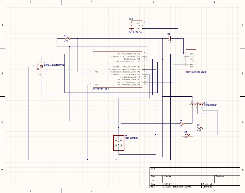
I started by drawing a schematic of the board using SolidWorks PCB.It allowed me to place all of the components on the sheet and then connect them to the appropriate pins using wires.
I then shifted my attention to laying out the components on the PCB and running traces. As you'll see later on, I had trouble machining the board because I failed to set the clearance and trace width to values that would allow a 1/32" bit to fit in between component pads. If you use SolidWorks PCB, be sure to change you settings under the "Design Rules" editor.

Once I had the traces all laid out, I exported them as a Parasolid file so I could open them in SolidWorks and process them a bit further. I changed the color of the board to white and the color of the traces to black. Then I created a 1:1 scale drawing of the board on a drawing sheet that I custom sized to 2" x 3" to match the size of my physical copper plated board.
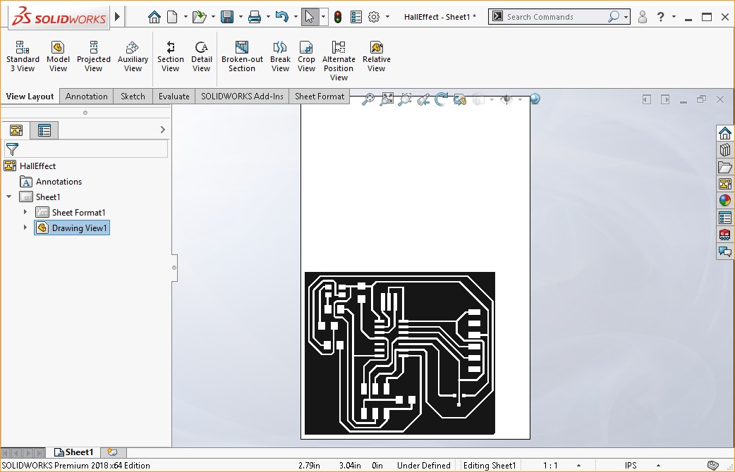
I saved the drawing as a PNG file and opened it in MODS so I could send the job to the Roland Precision mill.

As I mentioned above, my first attempt was a failure as the traces were not spaced far enough apart to accommodate a 1/32" tool. See the interfering traces and pads in teh circled areas?

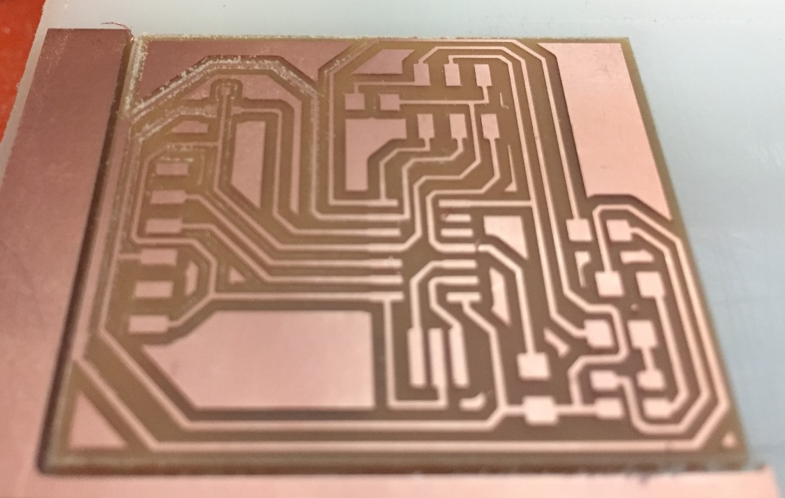
I adjusted the traces in SolidWorks PCB, exported it again to SolidWorks, updated the drawing, and generated a new PNG to cut. This time I was successful!
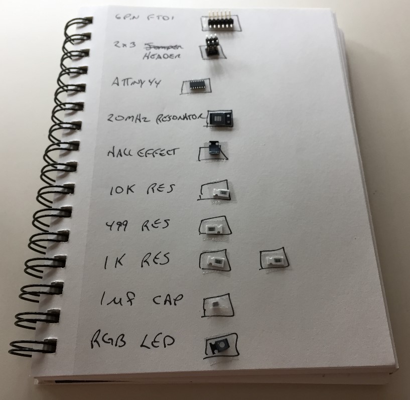
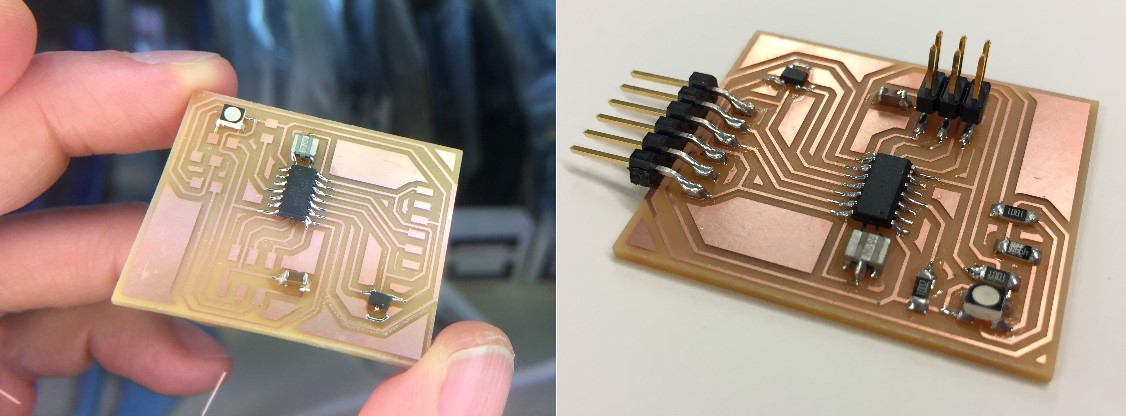
I wrote my Bill of Materials in my notebook and used double-sided tape to hold the parts in place while I gathered them.
Then I soldered the components in place.
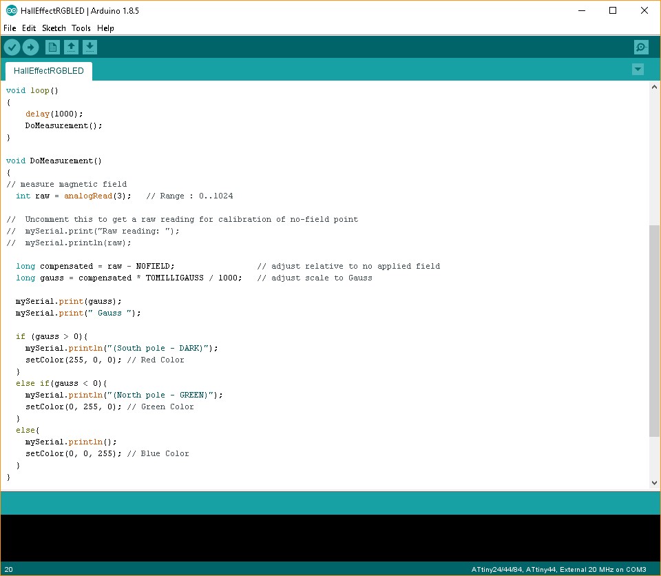
Turning my attention to writing the logic to control my board, I searched for some sample code from which to learn. I found a small sample on the Ardunio site . I used the code to calibrate my Hall Effect sensor's raw magnetic field reading, and then modified the code to send the magnetic field readings to the Serial Monitor.
Here it is in action - sending magnetic field readings back to the serial monitor every second!

...and here's an up close view of the hall effect readings. The 514 value is the default reading from the sensor. As the magnet gets closer to the sensor, the value increases (for the South pole) or decreases (for the North pole).

I initially consulted the Hall Effect Sensor datasheet to obtain critical dimensions for my design, but while reviewing it, I learned that this device can be used for more than just detecting the presence and strength of a magnetic field. Applied correctly, it can also be used to sense displacement, angular position, and measure current. I also found it interesting that the device is accurate across a wide temperature range, -40 to 150 degrees Celsius!