Exercise 06: Electronics Design
Electronics Design
- Group Project: Use the test equipment in your lab to observe the operation of a microcontroller circuit board
- Individual Project: Redraw the echo hello-world board, add (at least) a button and LED (with current-limiting resistor), check the design rules, make it (if you have time this week, test it).
My Process (Redrawing the Echo Hello-World Board)
:: March 5, 2018 ::
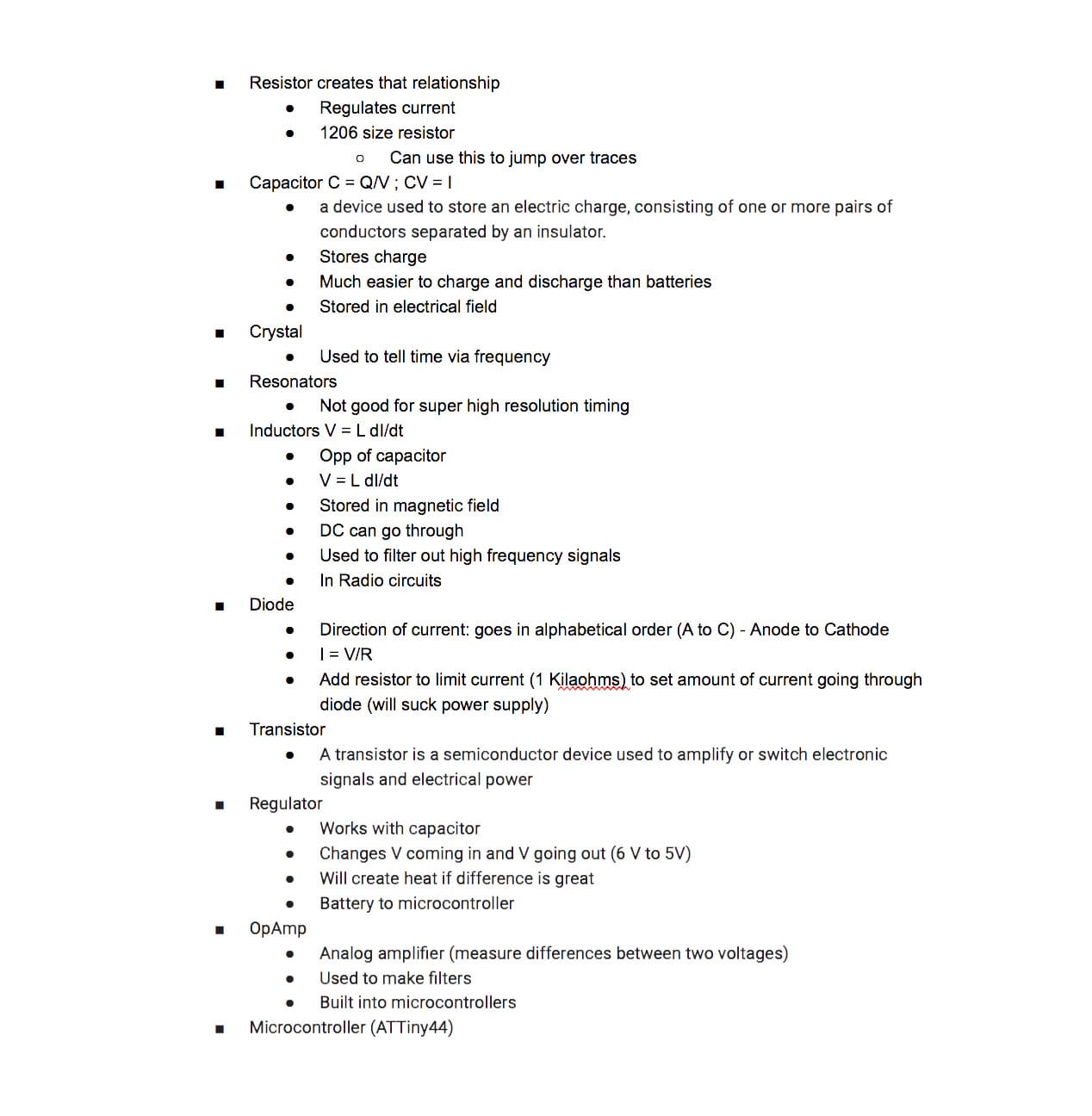
General Circuit Knowledge
Our assignment this week was two part: 1) A group assignment to use the test equipment in your lab to observe the operation of a microcontroller circuit board, and 2) an individual assignment to redraw the echo hello-world board, add (at least) a button and LED (with current-limiting resistor), check the design rules, make it, and, if I had time this week, test it. We completed the group assignment by playing around with an Arduino microcontroller that was in our lab.
For the individual assignment, I began by making myself more familiar with basic circuit knowledge and understanding the functions of each of the components on the board.
When working with circuits, the main concepts that we need to be familiar with are Voltage(V), Current(I) and Resistance(R).
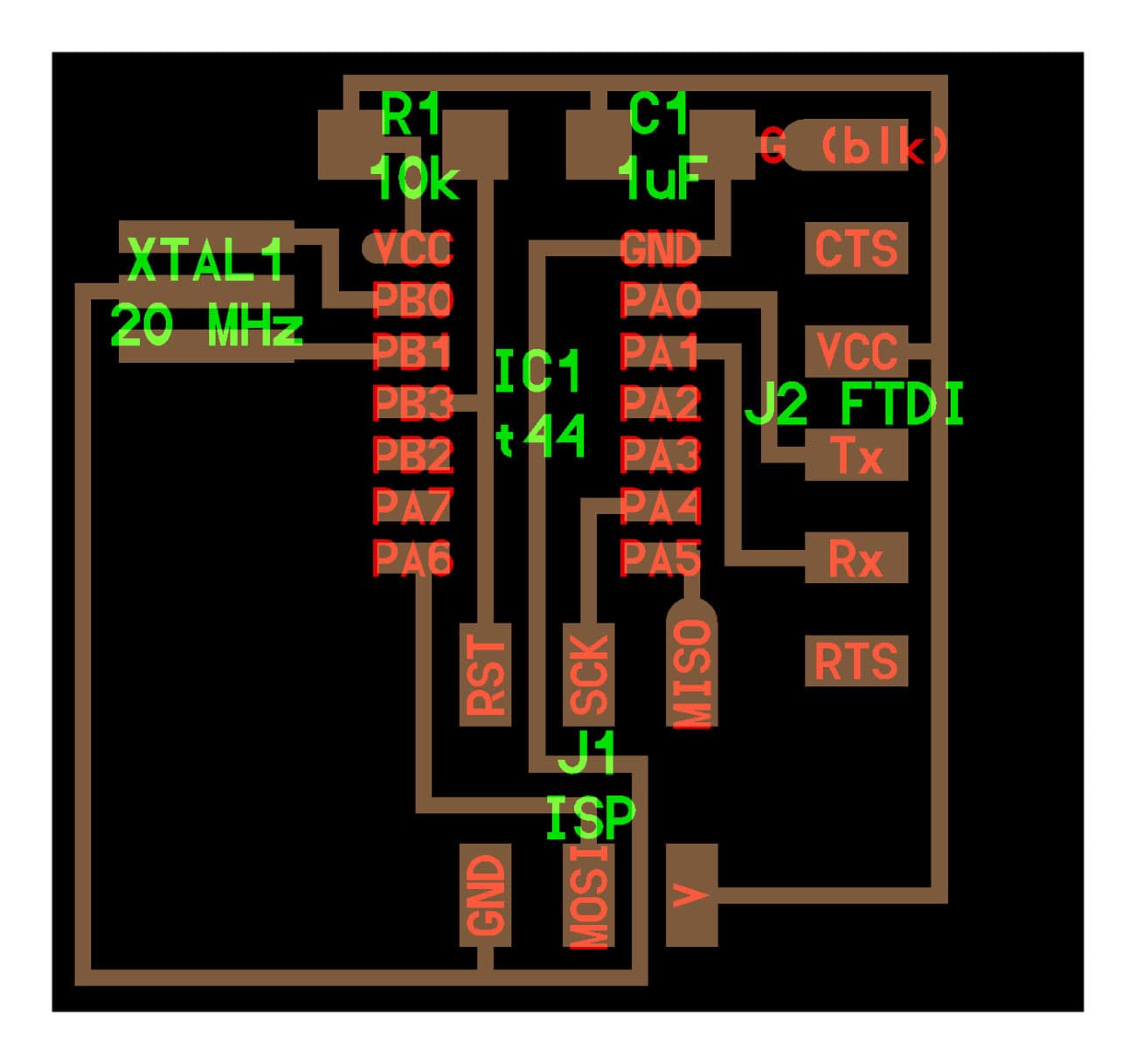
Redrawing Echo Hello-World Board
The software I used to design my board was Eagle, which I had never used. The process of learning Eagle was a bit frustrating as the software has quite a few kinks and the UI isn’t great. But I persisted.
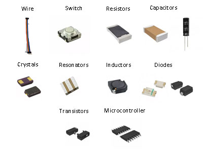
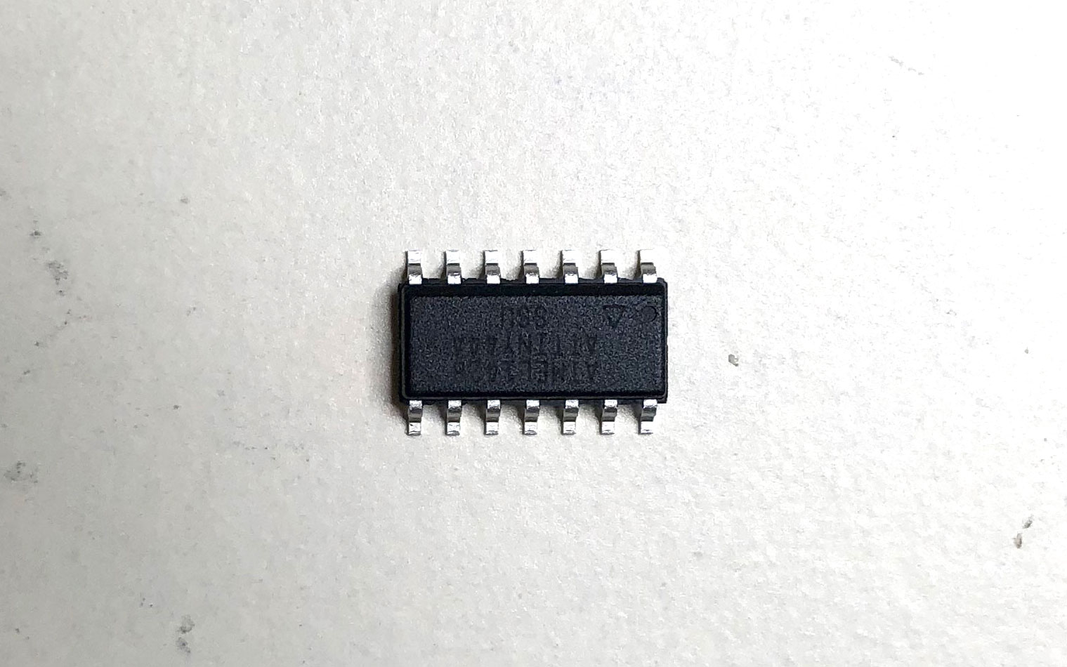
First thing I did was figure out what components I would be using as part of my board.
Parts on the Hello Echo Board:
I also studied the standard Fab Academy Echo Hello-World Board.
To learn Eagle, I followed the tutorial on Fab Academy. I went through it first and then followed the tutorial step by step while creating my own board.
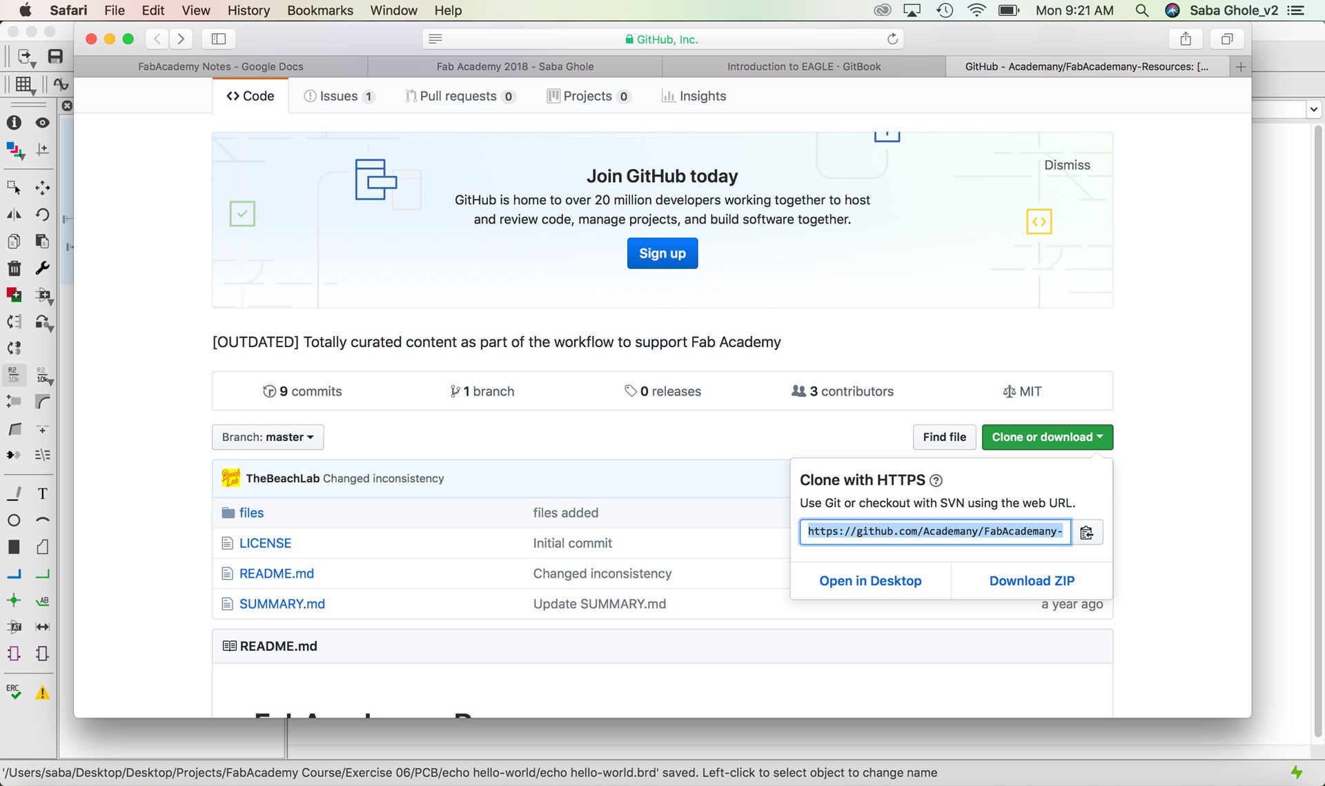
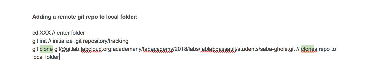
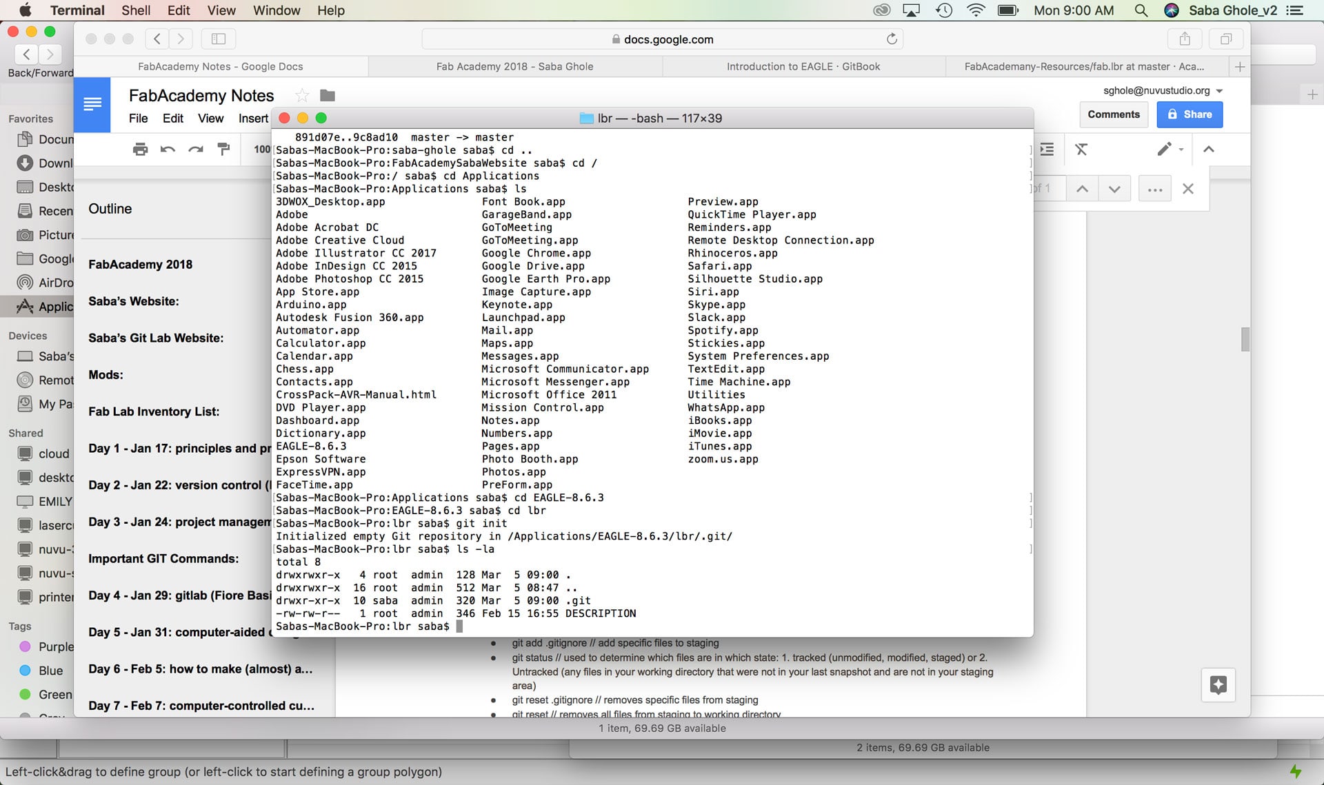
The first thing I did was download and install the Fab Academy component libraries. After this, I could access all of the libraries associated with a component.
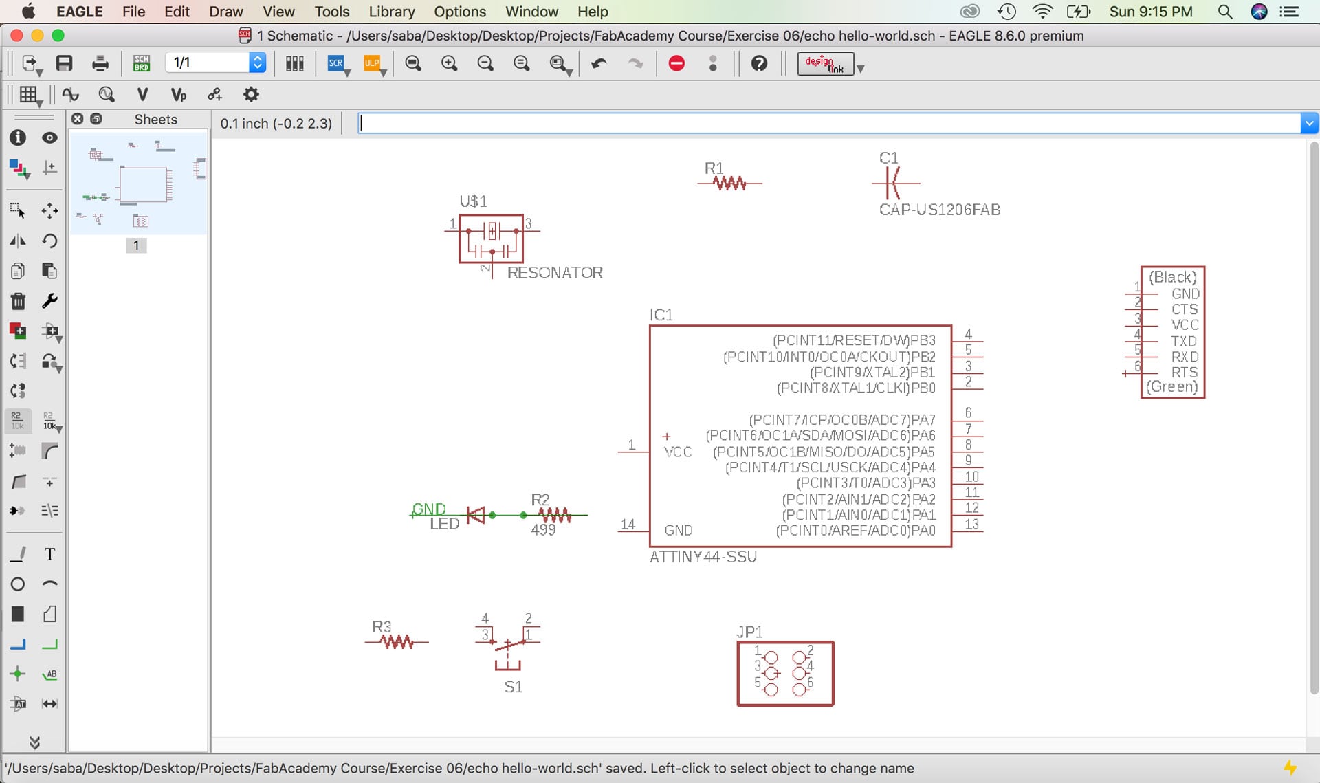
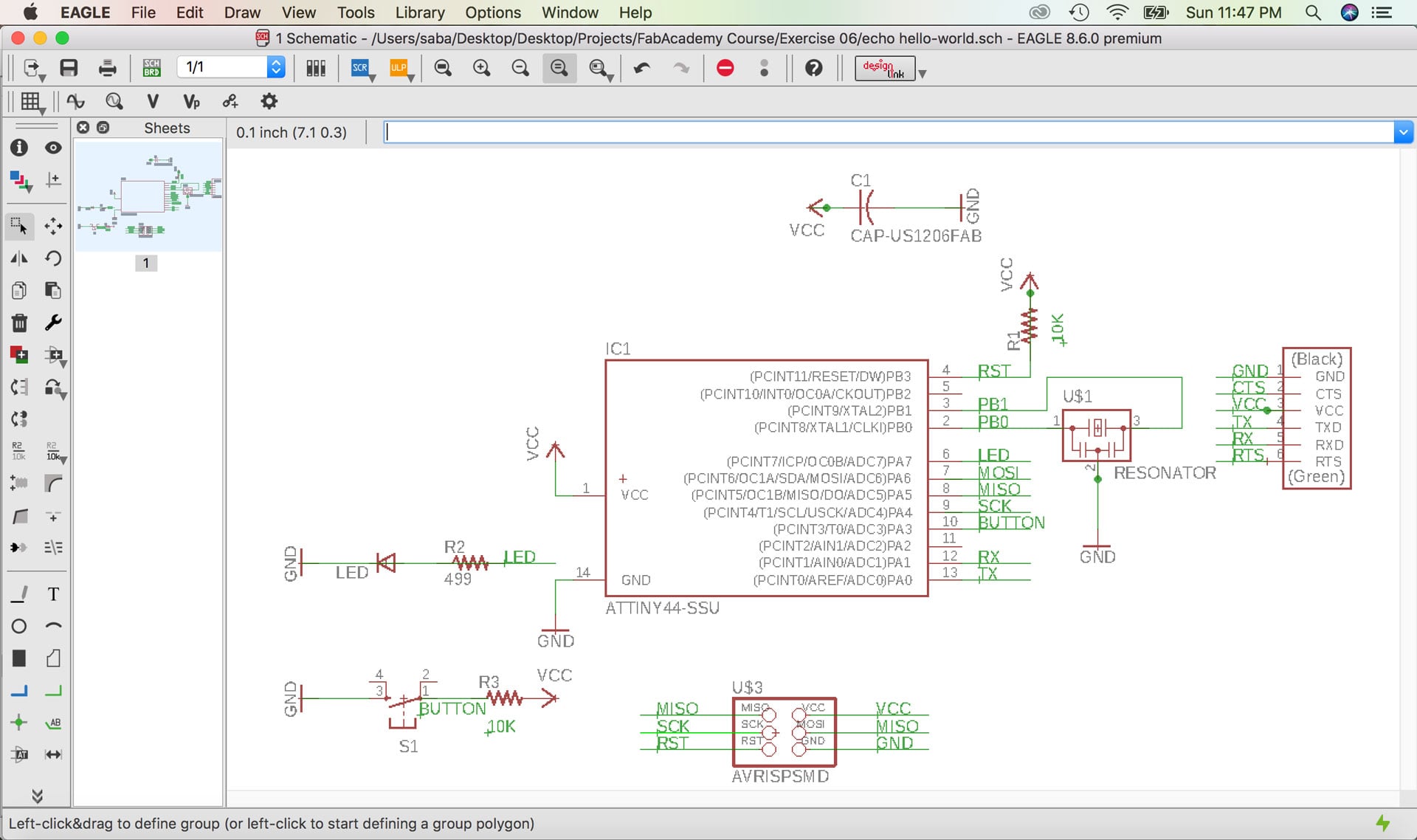
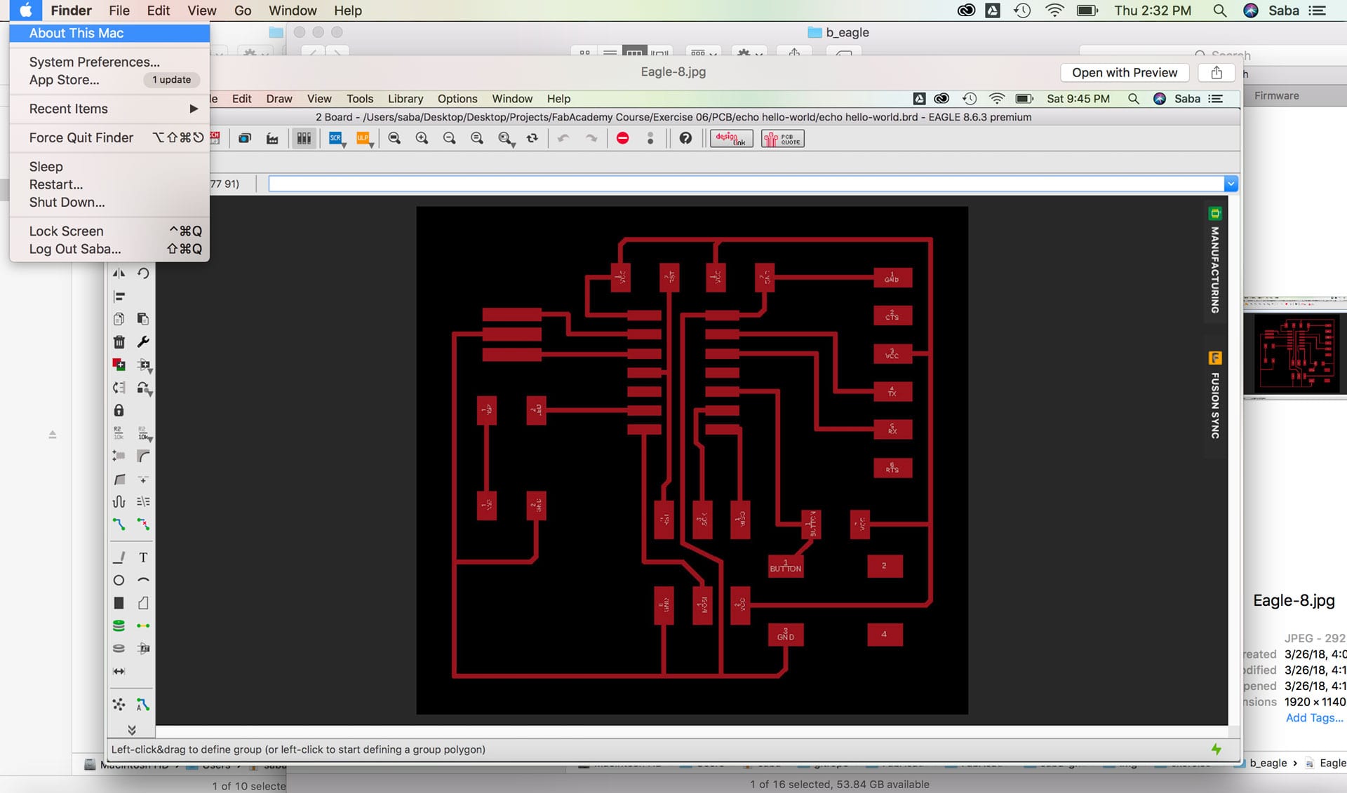
I began laying out my board in the Schematic window. I added all of the components and placed them in the schematic generally where I imagine them being placed on my board. I then used the “net” command to create traces to connect components. To connect components located at a distance from one another, I used the “name” command to change the name of the trace and connect it to another component. I also used the “text” command to label all of the traces.
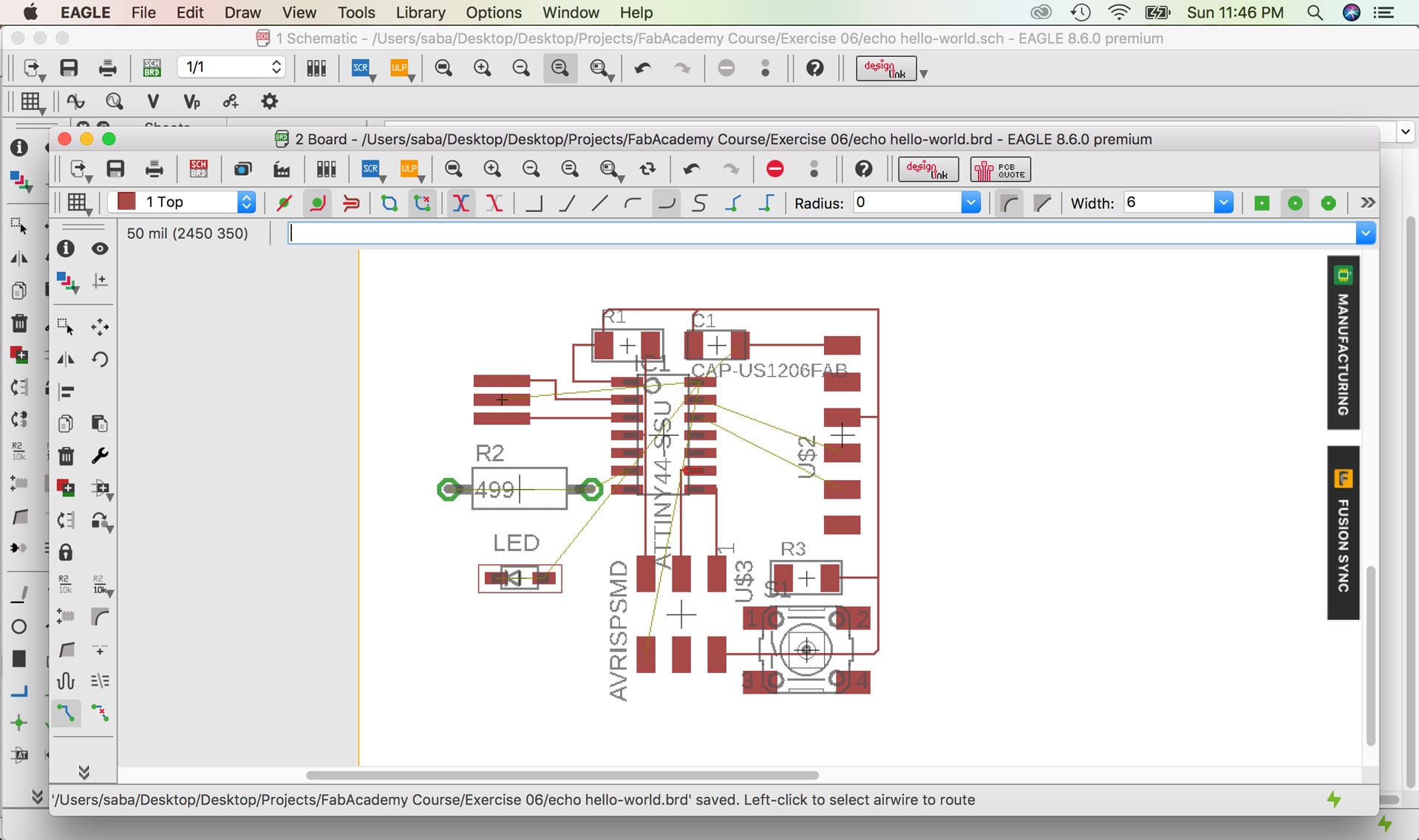
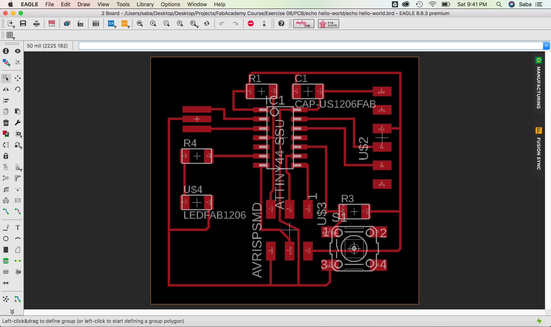
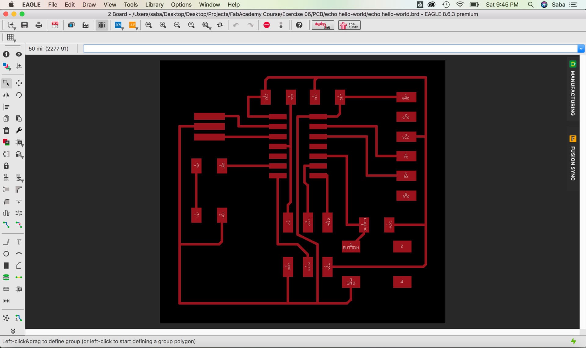
Once I had laid out all of the components and created all the NETS in the Schematic View, I switched to the Board View. I moved the components a bit to provide a bit of spacing and arrange them in the right place on the board. I then used the “route” command to route each trace manually.
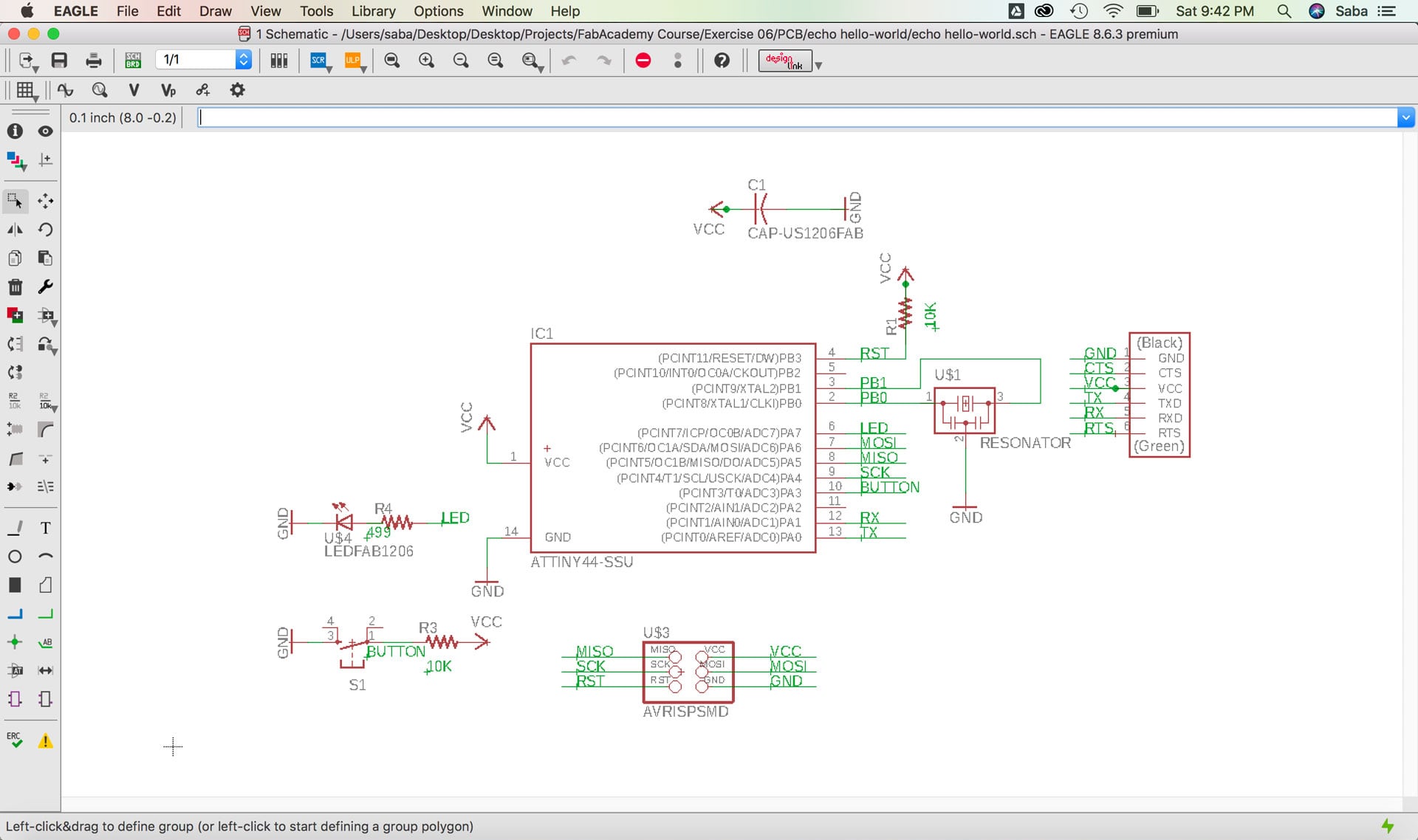
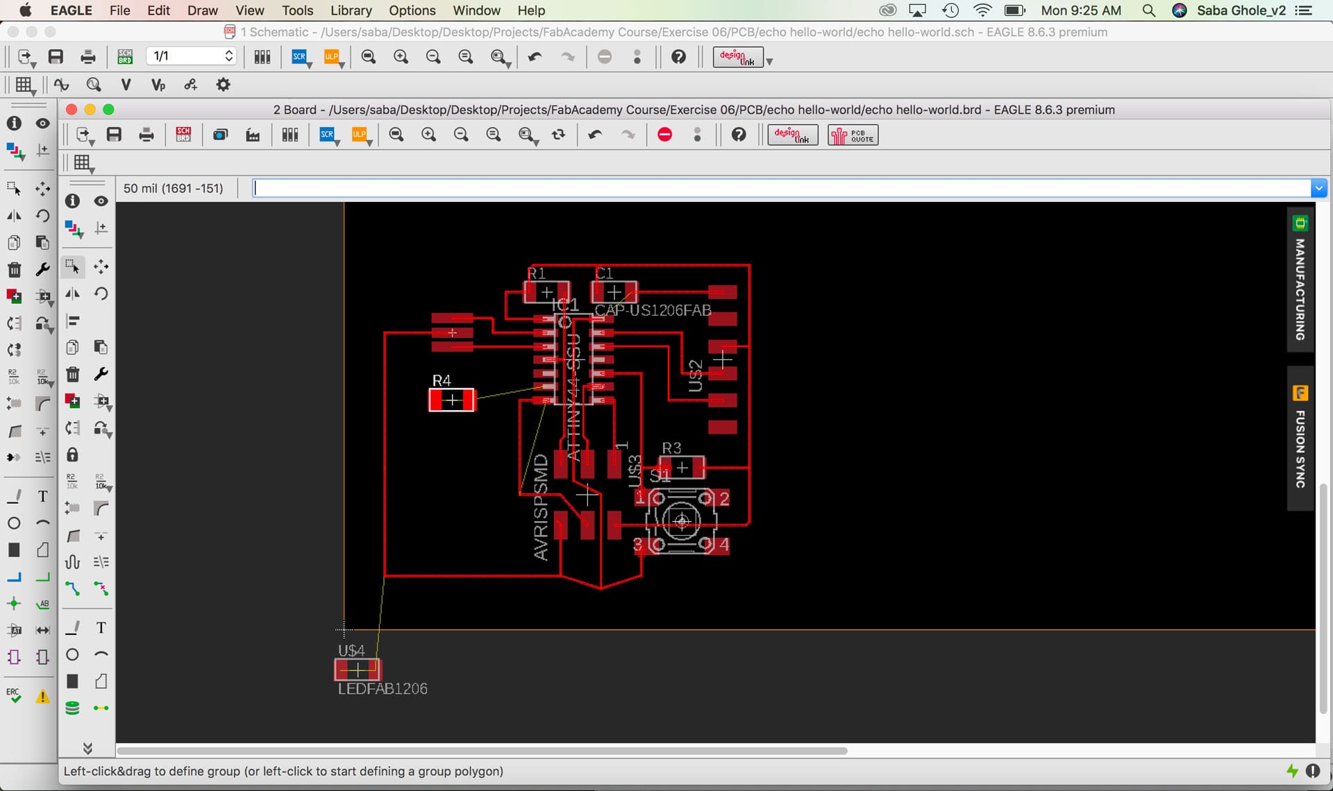
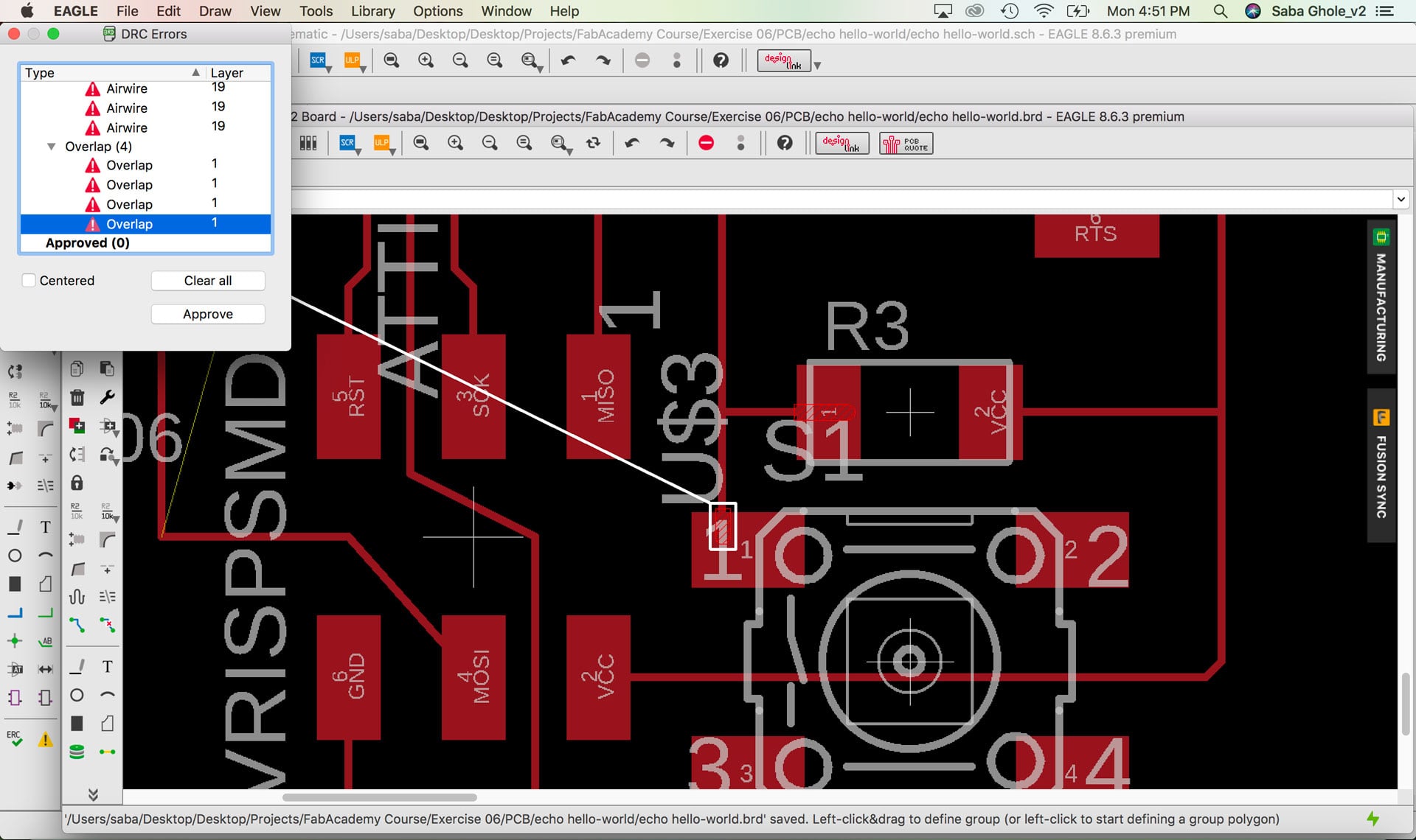
I downloaded the Fab Academy Design Rules Check (DRC) script to verify that all my spacing between components and traces is adequate. Given that I will be using an endmill of 1/64”, it needs to be able to to go between all the traces so the machine is able to cut the board successfully. There were a number of issues when I ran the “drc” command, which I slowly worked through to fix. It seems that many were related to components not being properly connected to GRD via the NET as well as overlaps in the component and trace. I went back into Schematic View to correct many of the errors until I had no errors (ya!).
Preparing Board for Milling
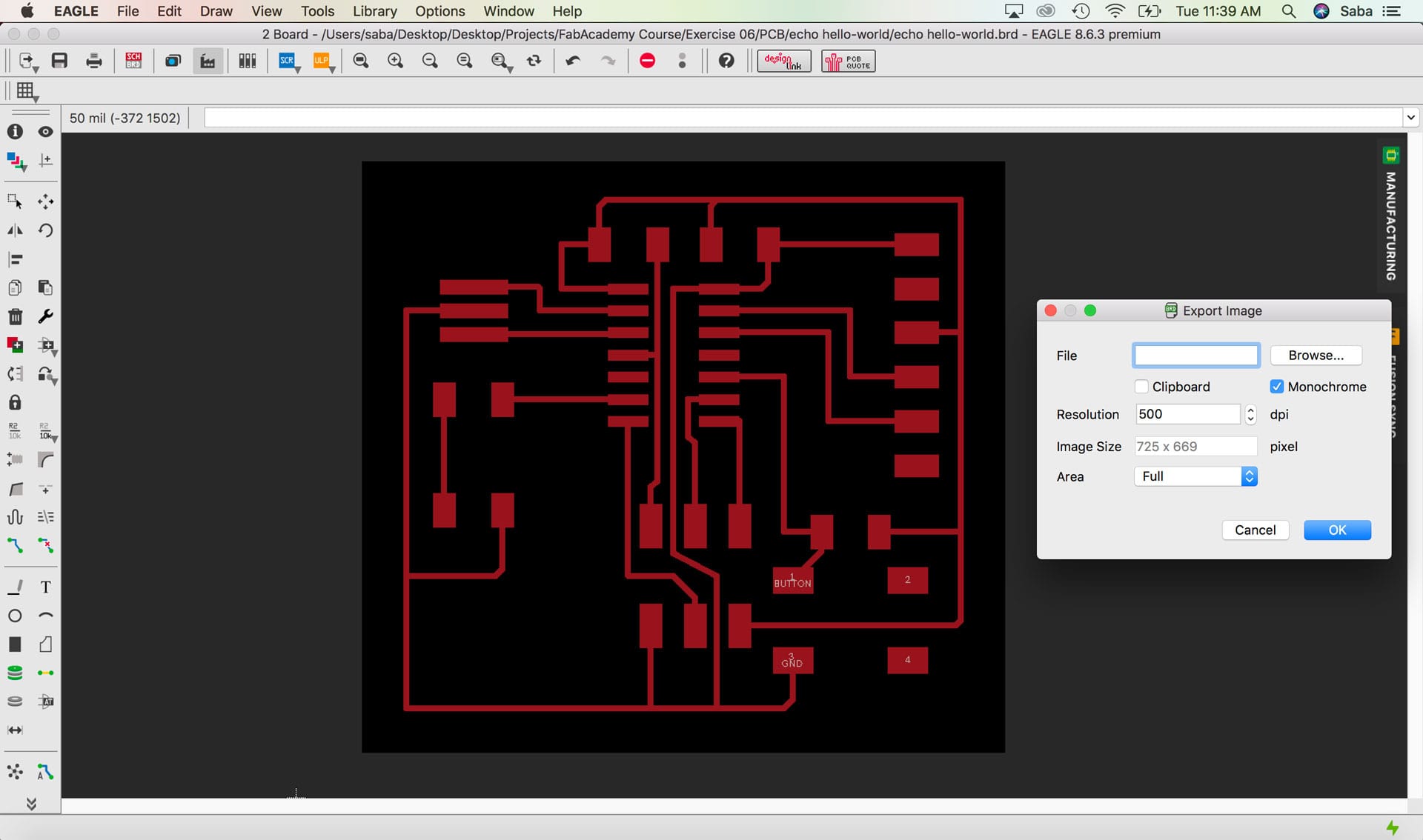
To prepare the board for milling, I went to layers menu and selected only the top layer and exported the file as a PNG with settings for monochrome and 500 DPI. This created a black and white image of the traces of my echo hello-world board. To create the outline PNG file, I added a white border of 20px in Photoshop.
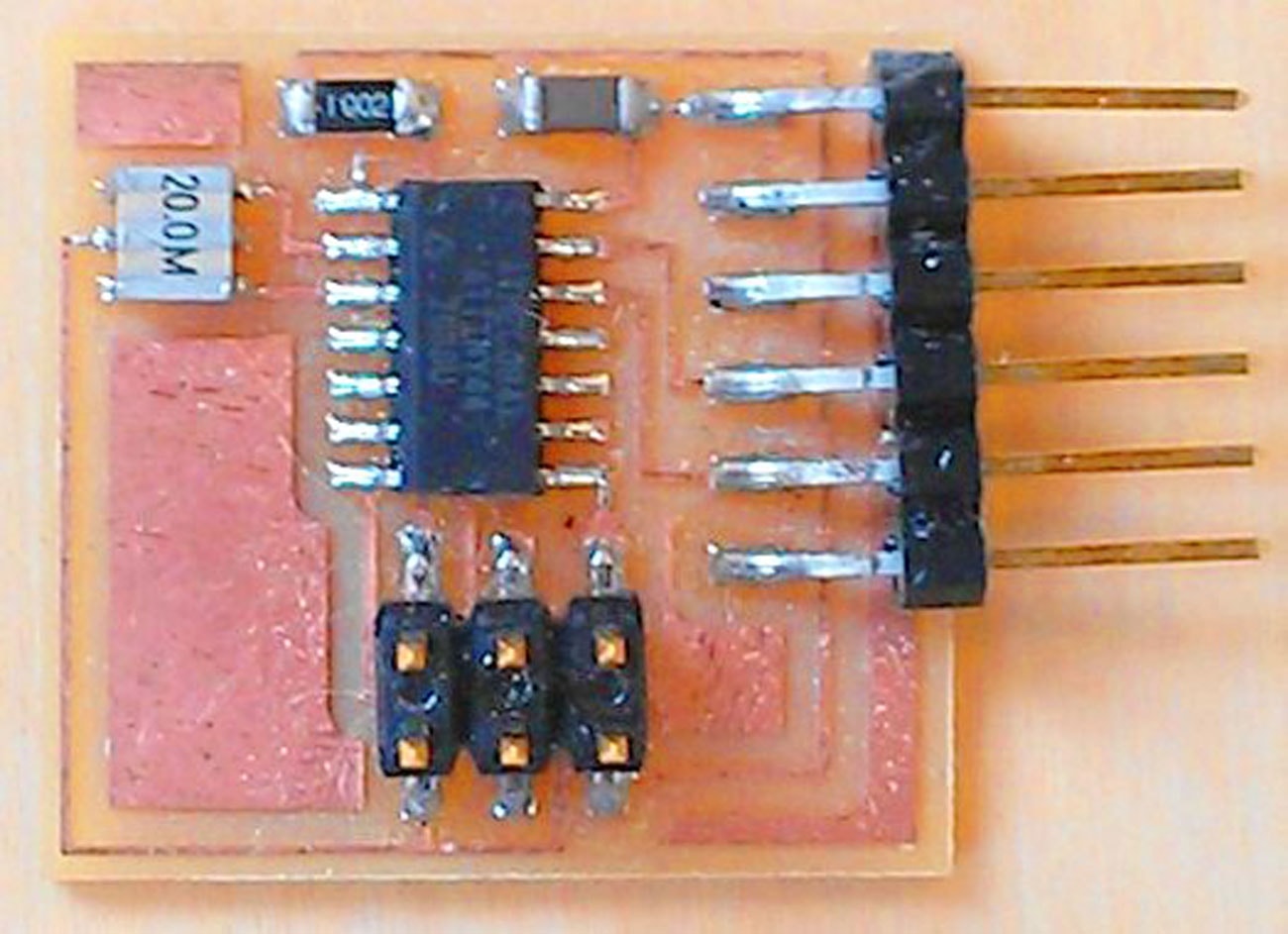
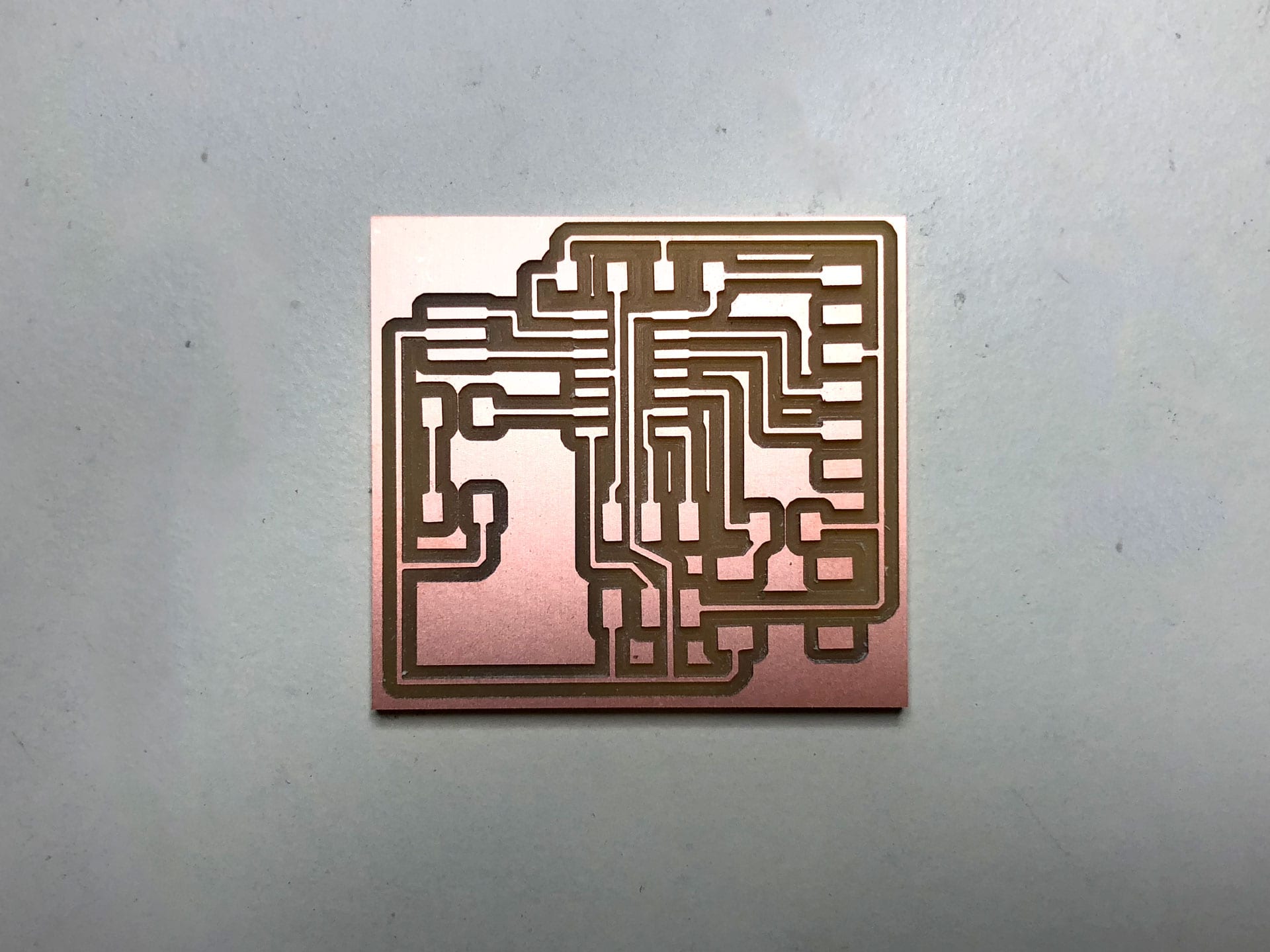
Milling the Board
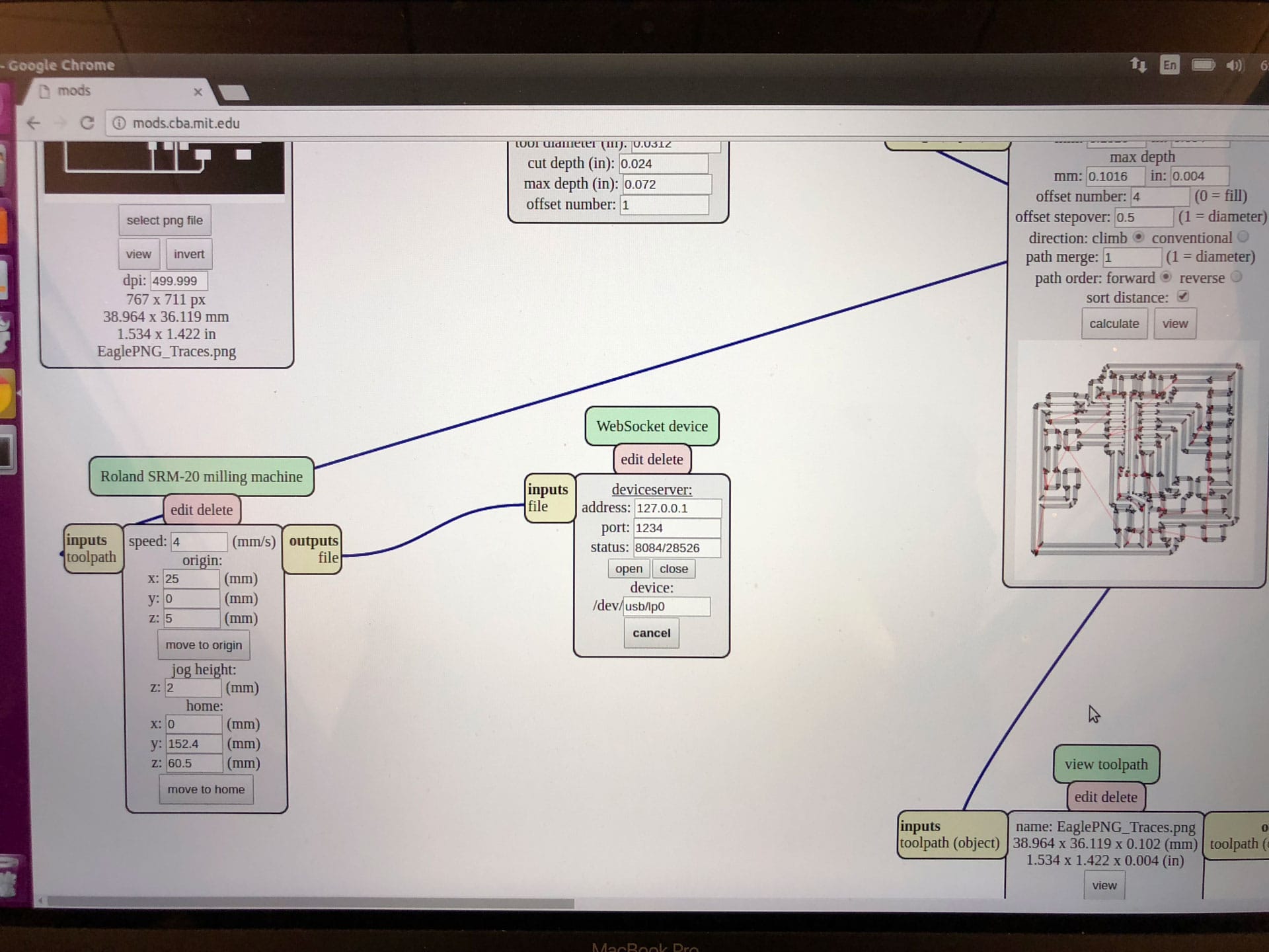
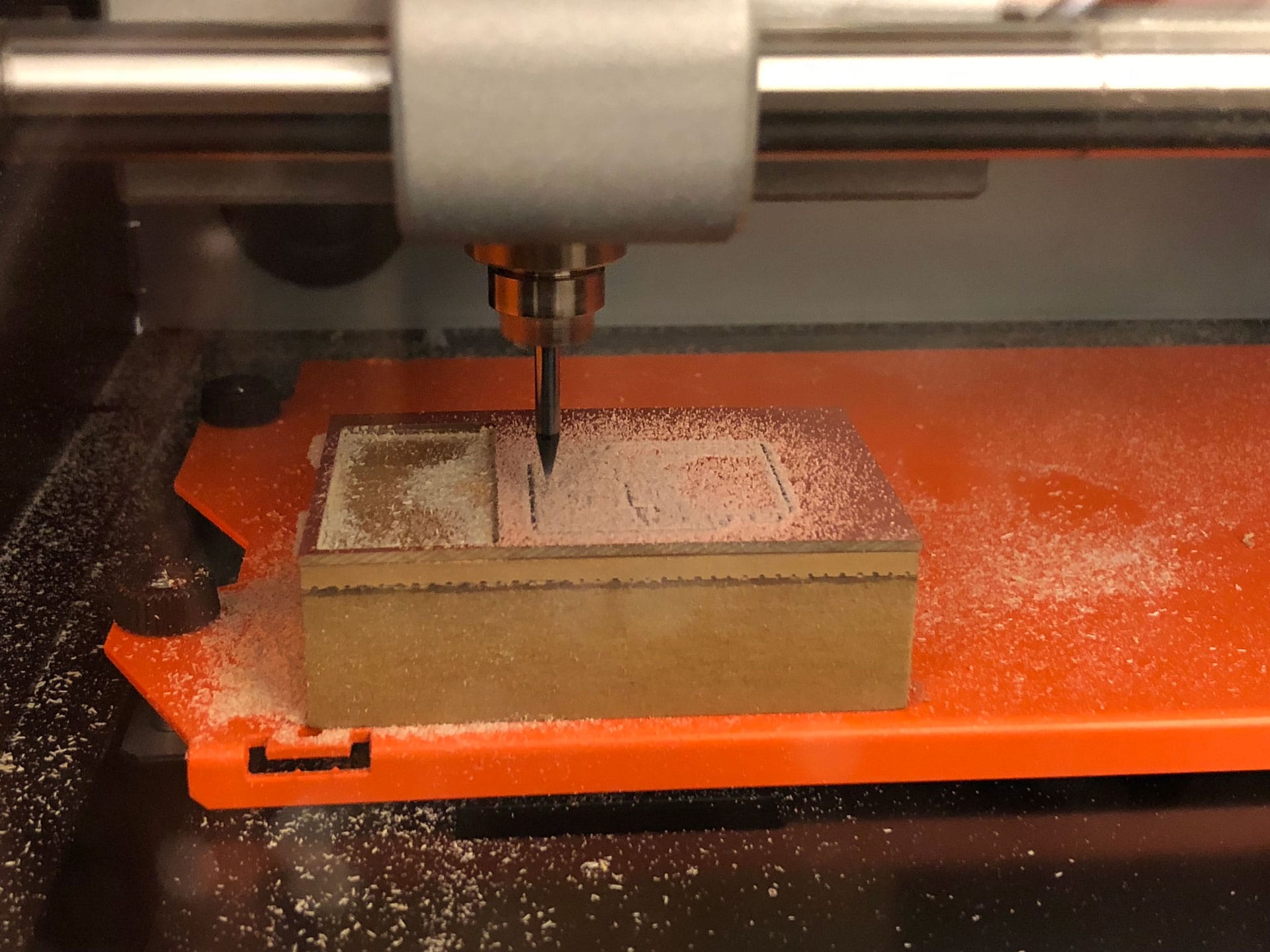
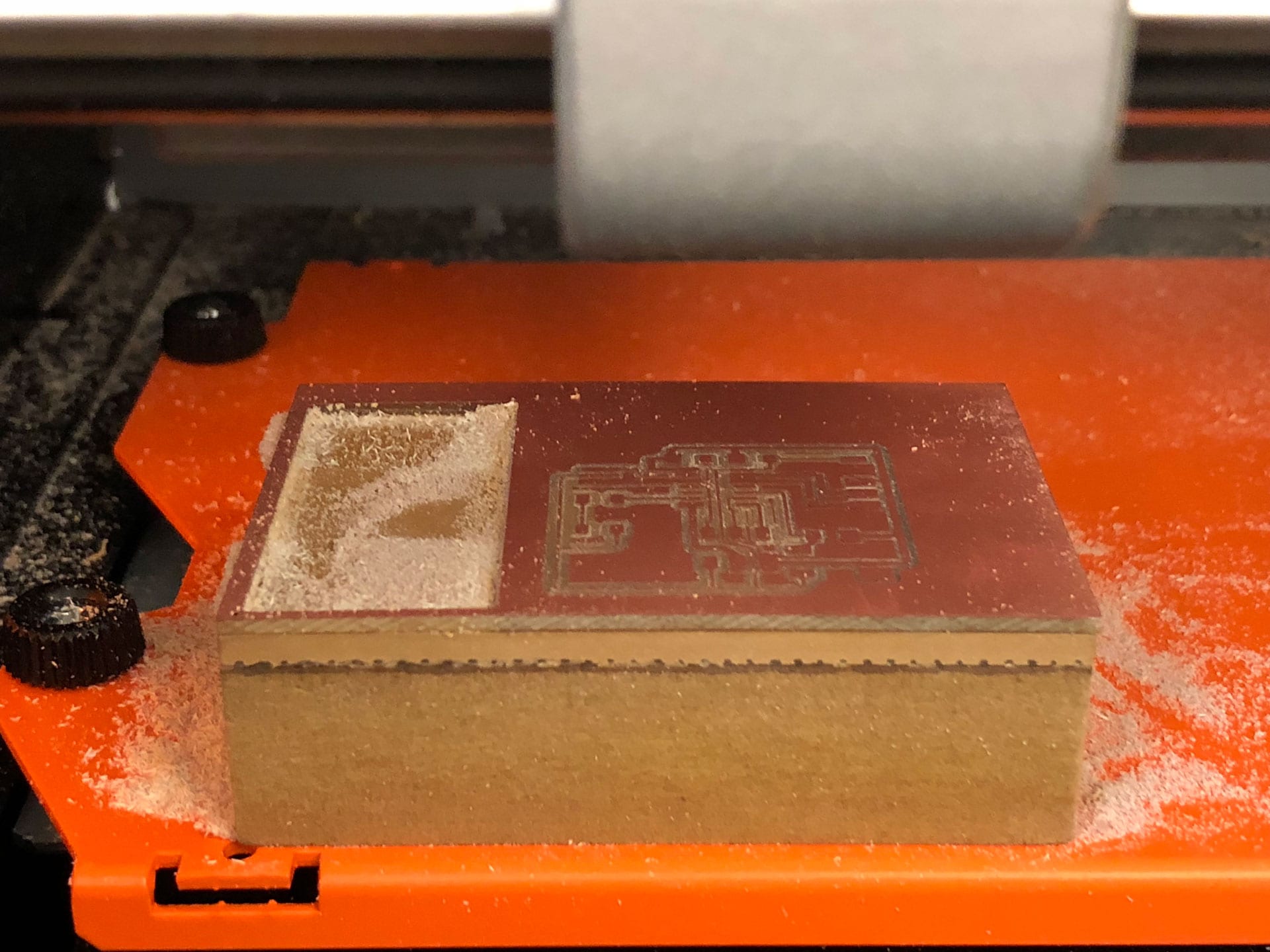
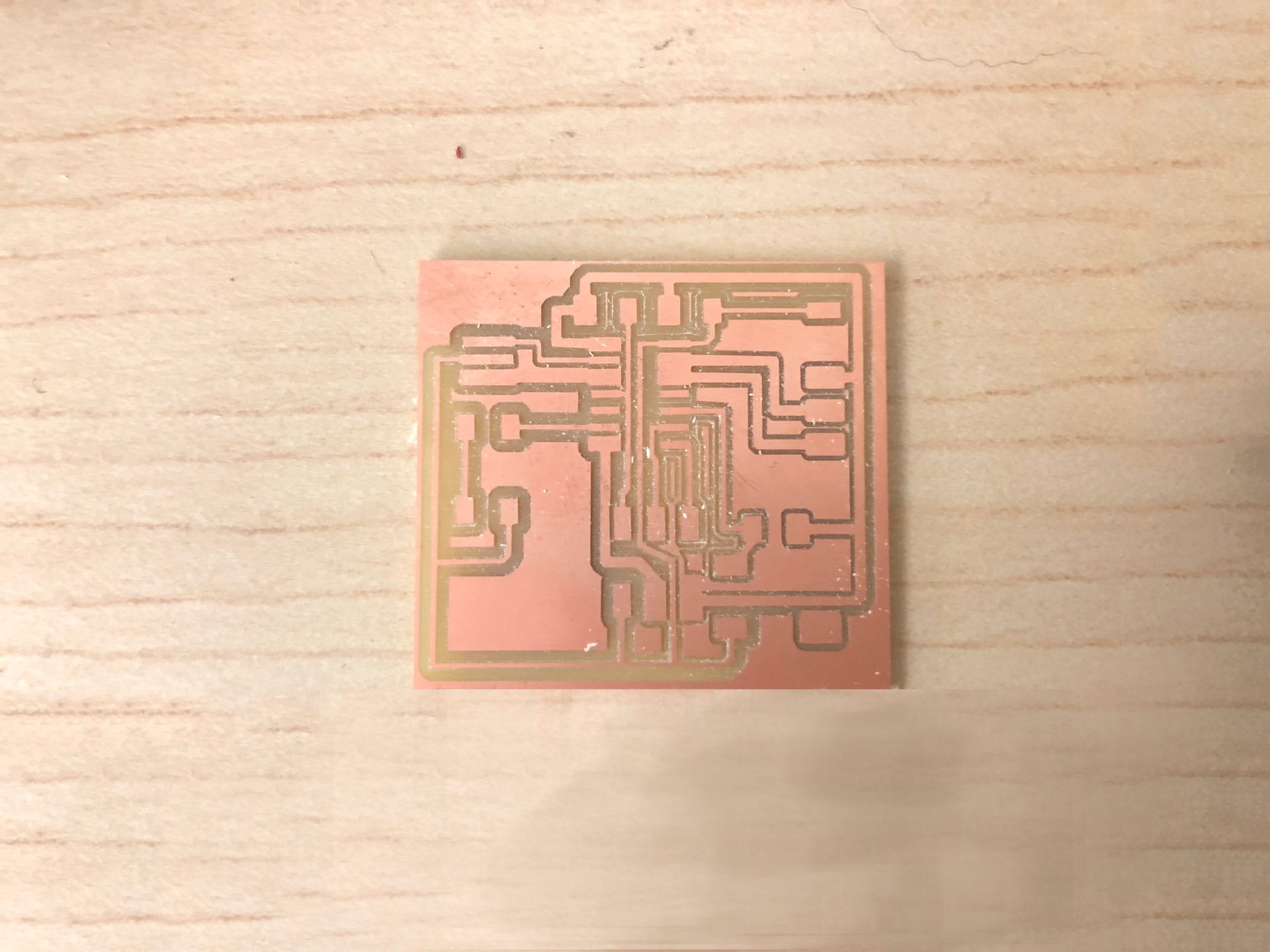
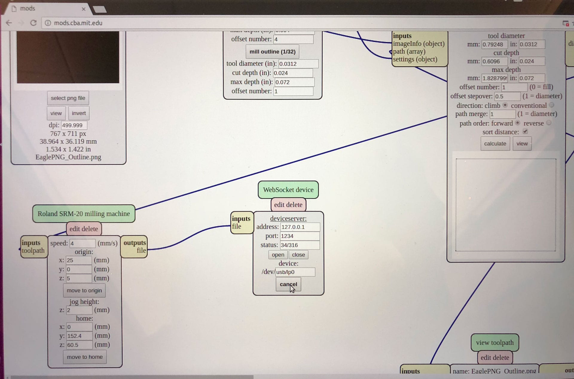
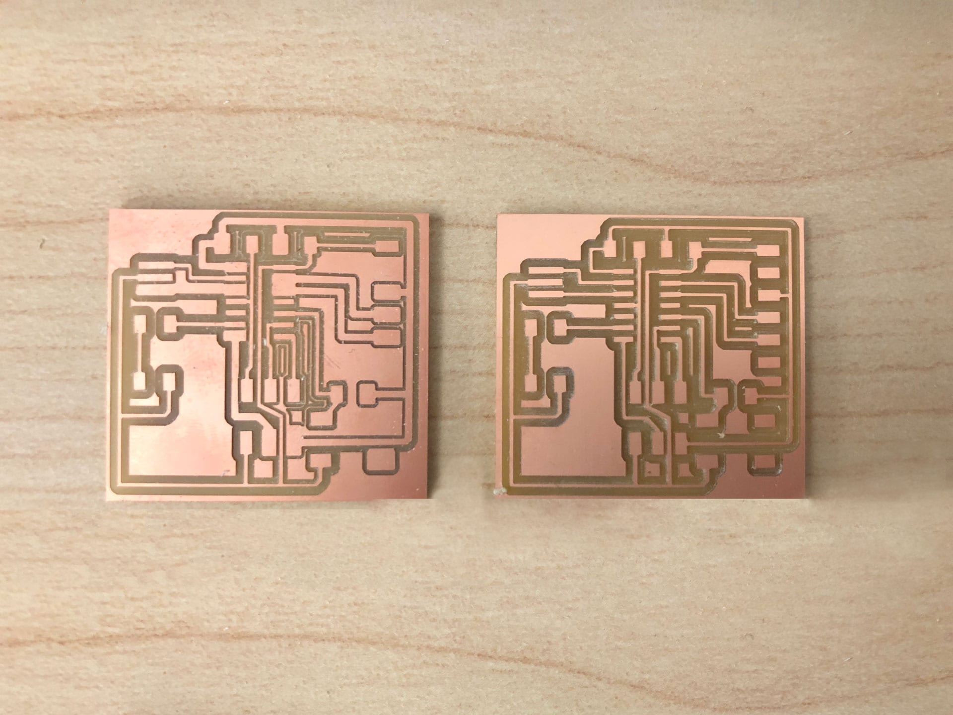
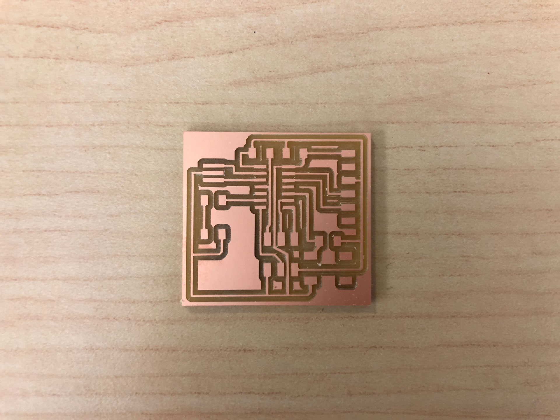
I used the Modela machine at the CiC to mill my board finally (thanks Luciano for helping through this process!). I used Mods to set up the machine to cut my traces PNG file first. Unfortunately, the Modela did not complete the full milling process and many of the traces were left uncut or partially cut on my board. I had to repeat the process and the second time. Things worked much better the second time around and my board was milled successfully. My traces turned out a bit thinner than expected, so next time, I will try to vary the offset number to get a thicker trace.
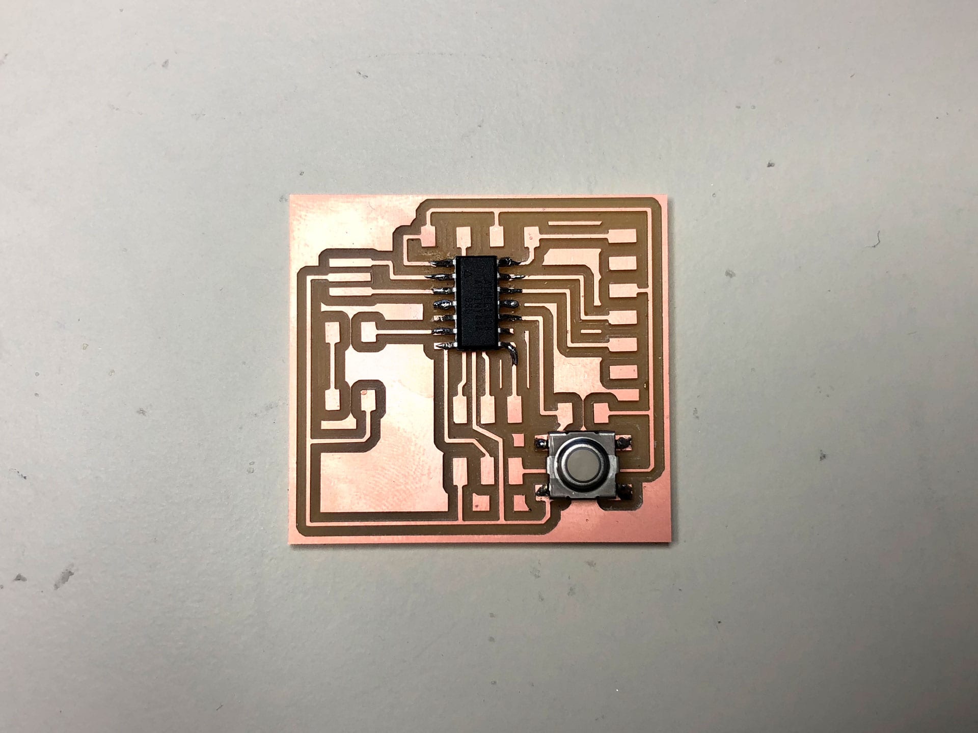
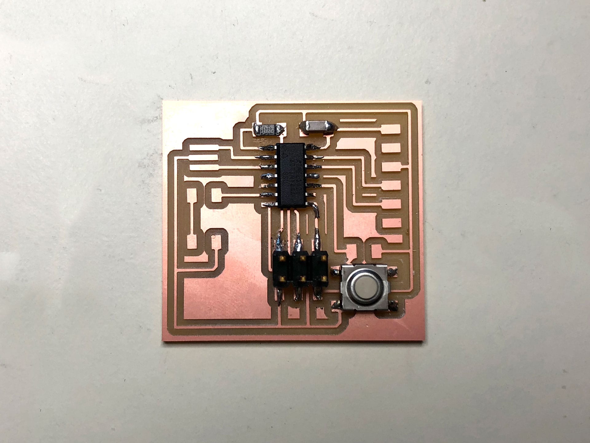
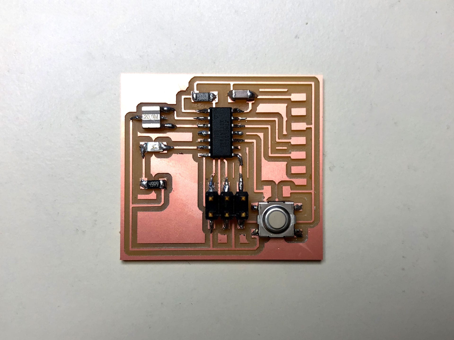
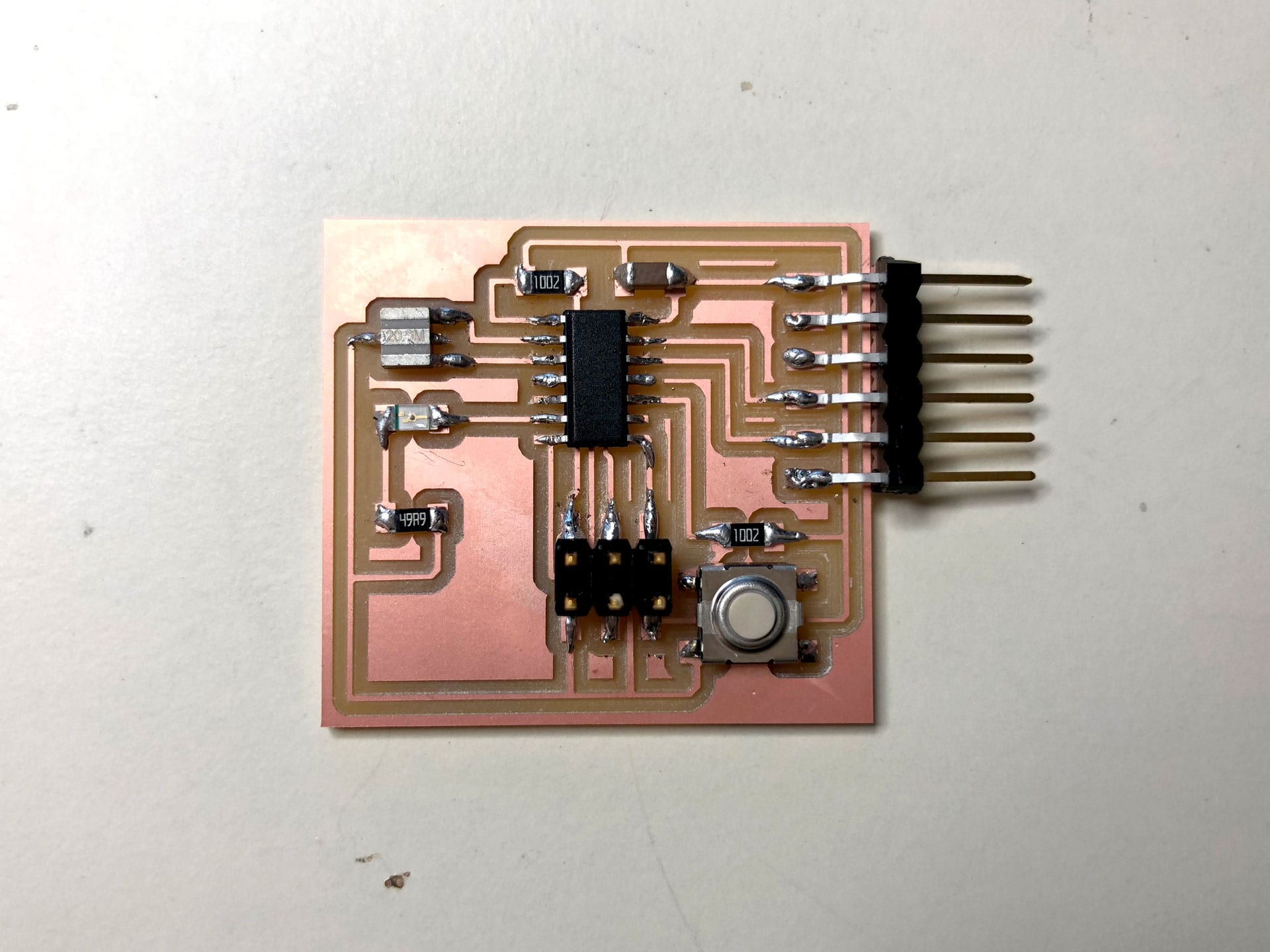
Soldering the Components
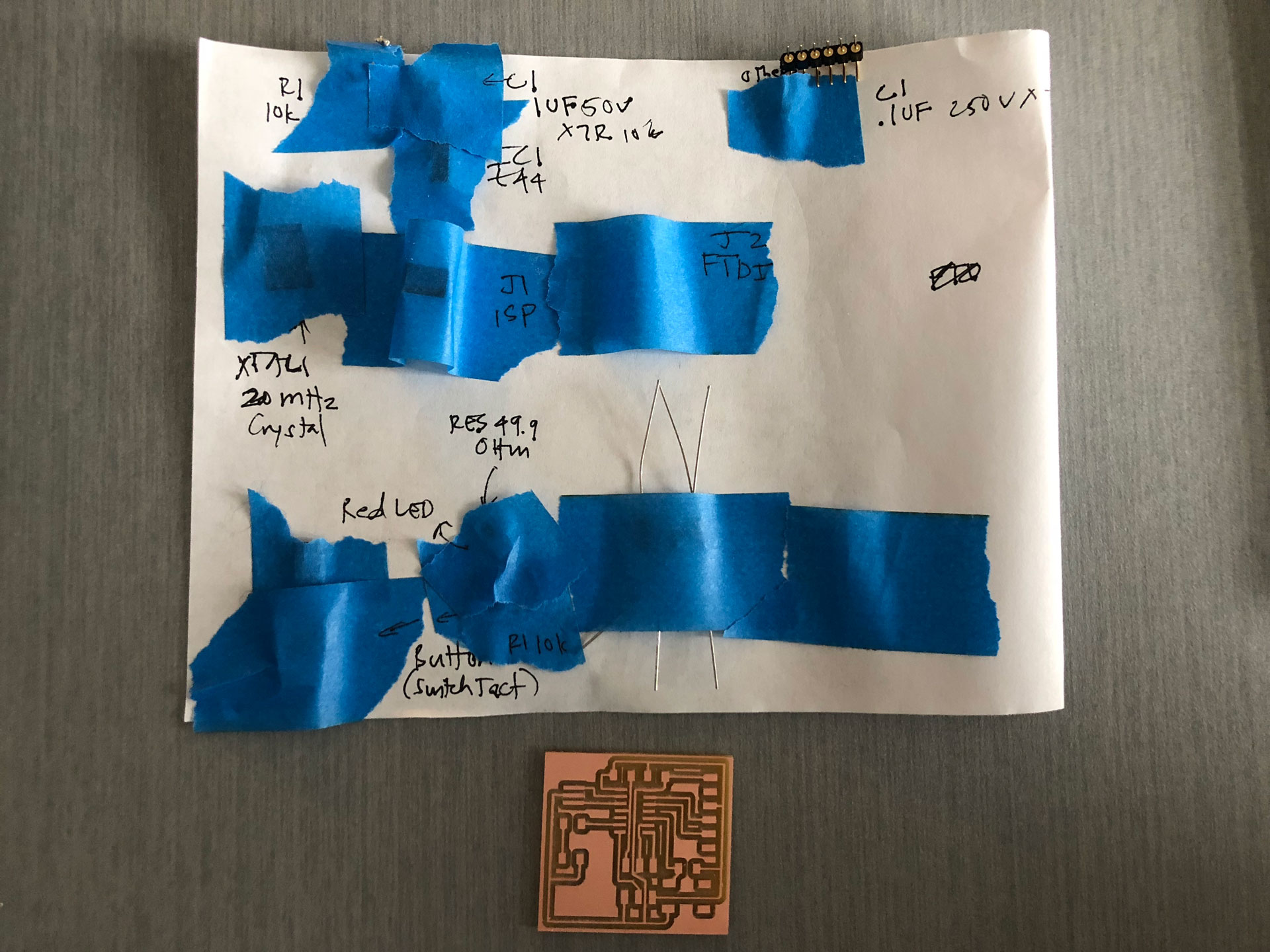
For soldering the components, I first figured out the order for soldering the various components based on their location and height as well the directionality of the components.
Programming the Board
The next step was programming the board. This took some time and many iterations to get right. I wanted to use my FabTiny Programmer (that I had built a few weeks ago) to program the ATtiny. I decided to use the Arduino IDE with an to program my ATtiny board. I referenced the tutorial on Fab Academy for support while going through this process as well as the support of my instructors (thank you Luciano & Jeanmichel!!).
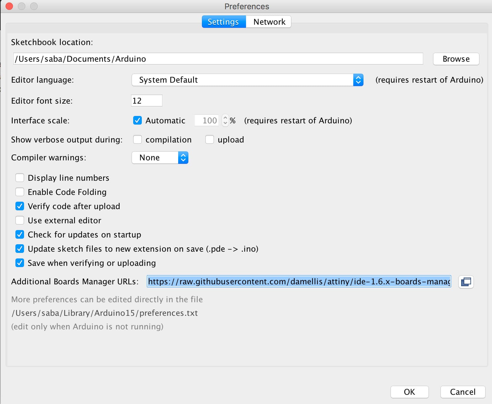
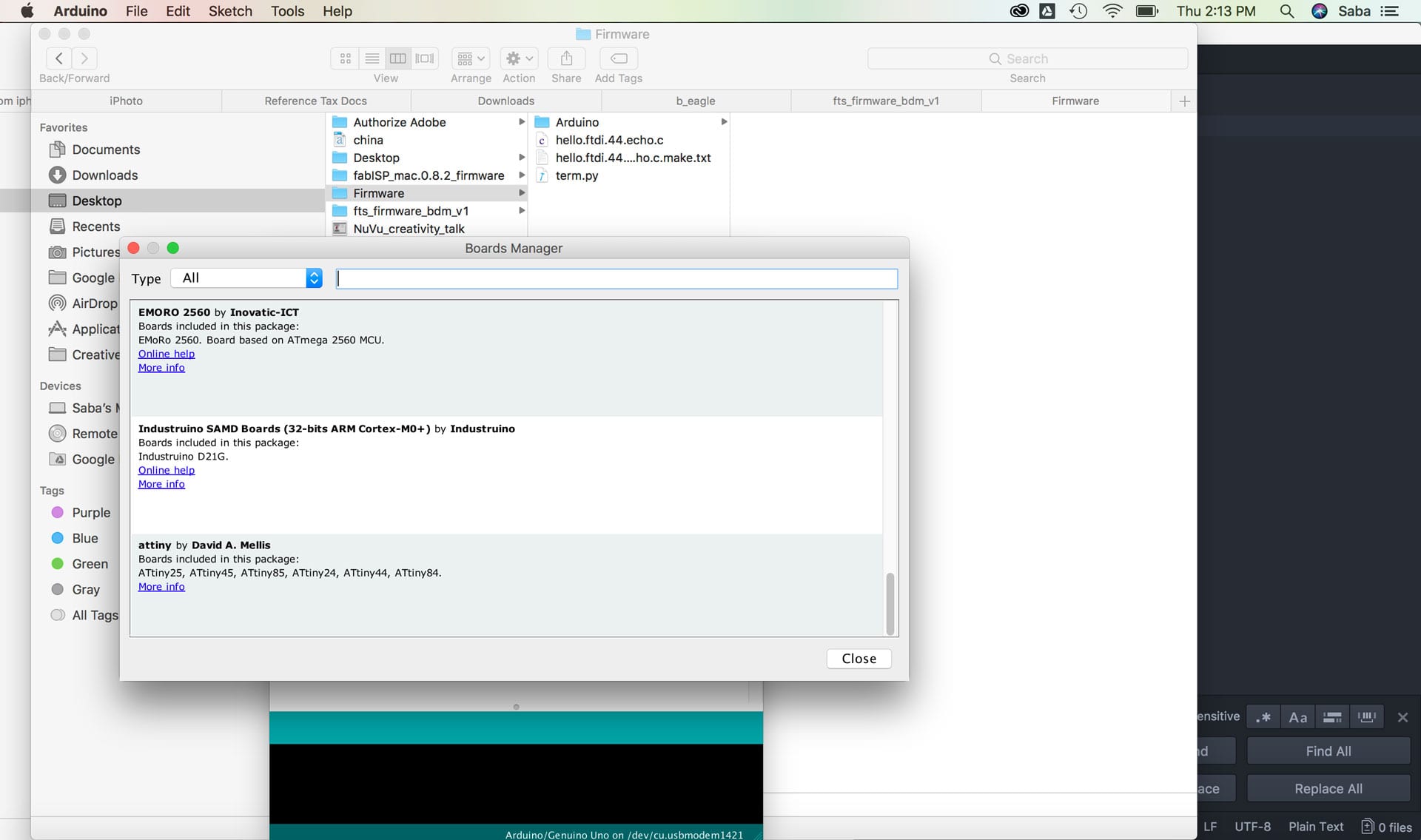
I began by installing the ATtiny support in Arduino. To make arduino ATtiny compatible we need to install the ATtiny support. Details are explained at the High Low Tech group site. I installed the ATtiny support using the built-in boards manager. I had to paste the following URL into the field (use a comma to separate it from any URLs you’ve already added):
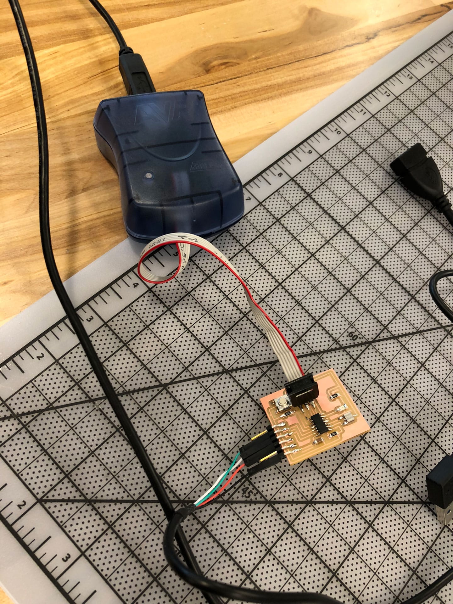
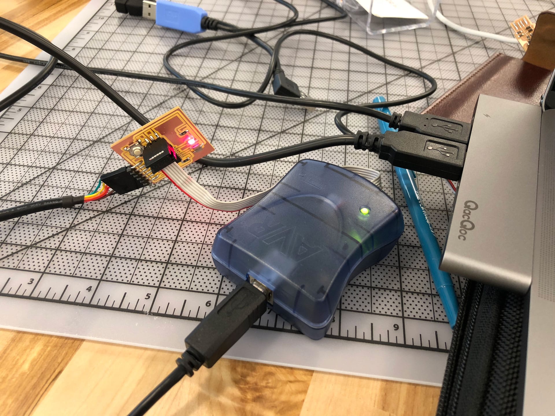
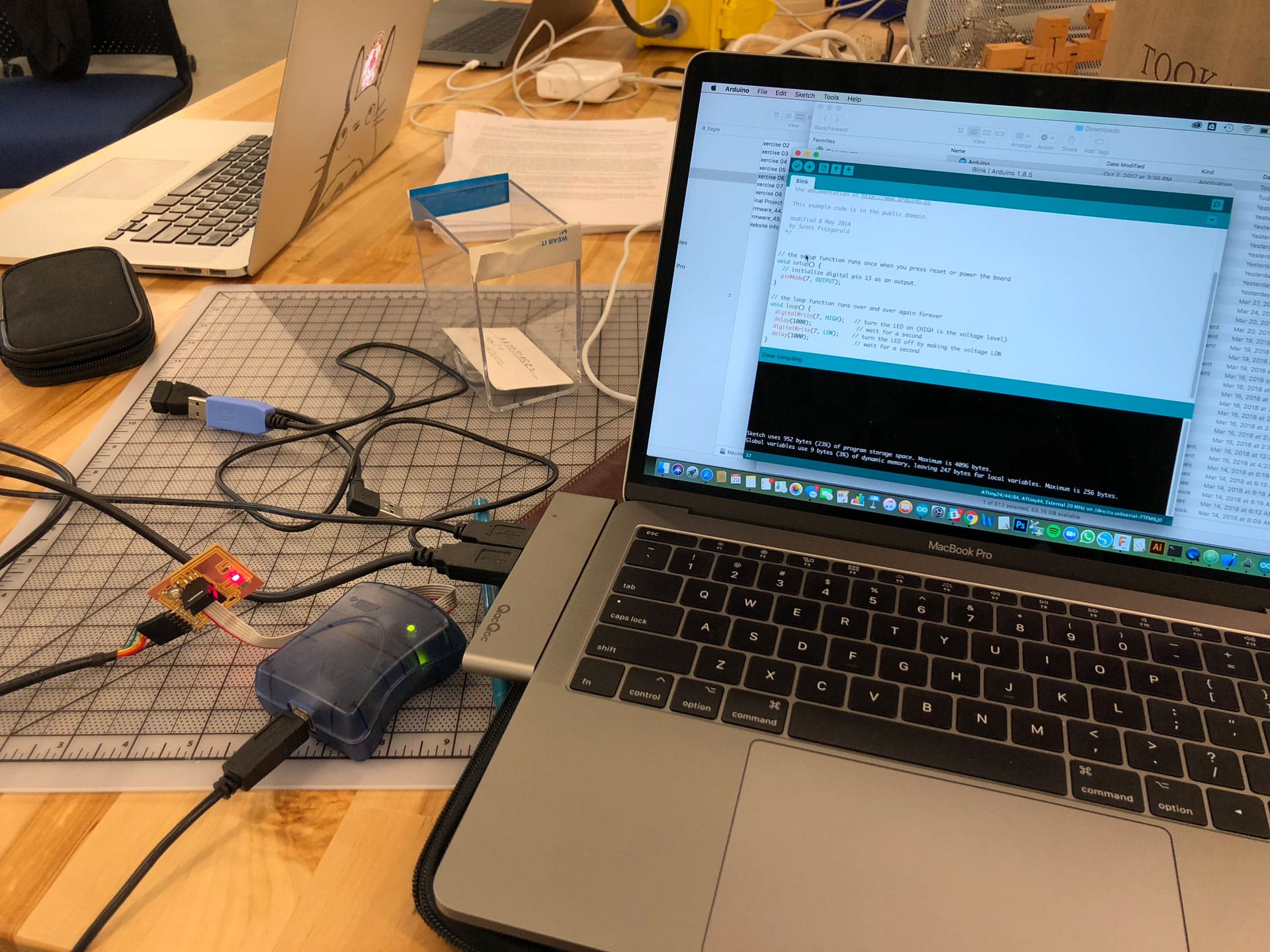
I then needed to provide power to the ATtiny and connect it to my Programmer (FabISP) and make sure that I was connecting MISO, MOSI, SCK, RESET, VCC, and GND of the Programmer to the corresponding pins on the ATtiny. I connected my FabISP to the ATtiny using the ISP header. I then connected the FabISP to my computer’s USB port and then powered the ATtiny using an FTDI cable.
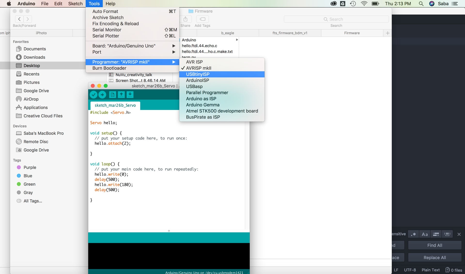
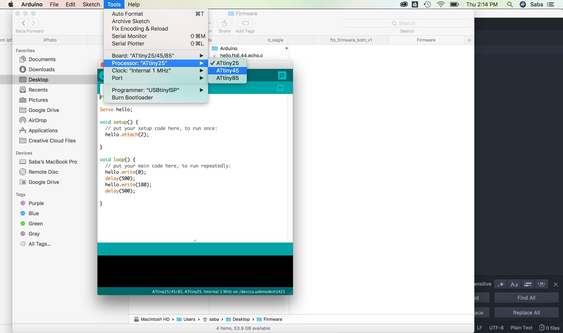
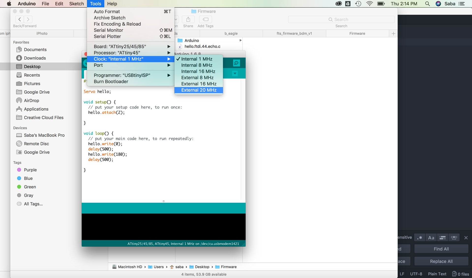
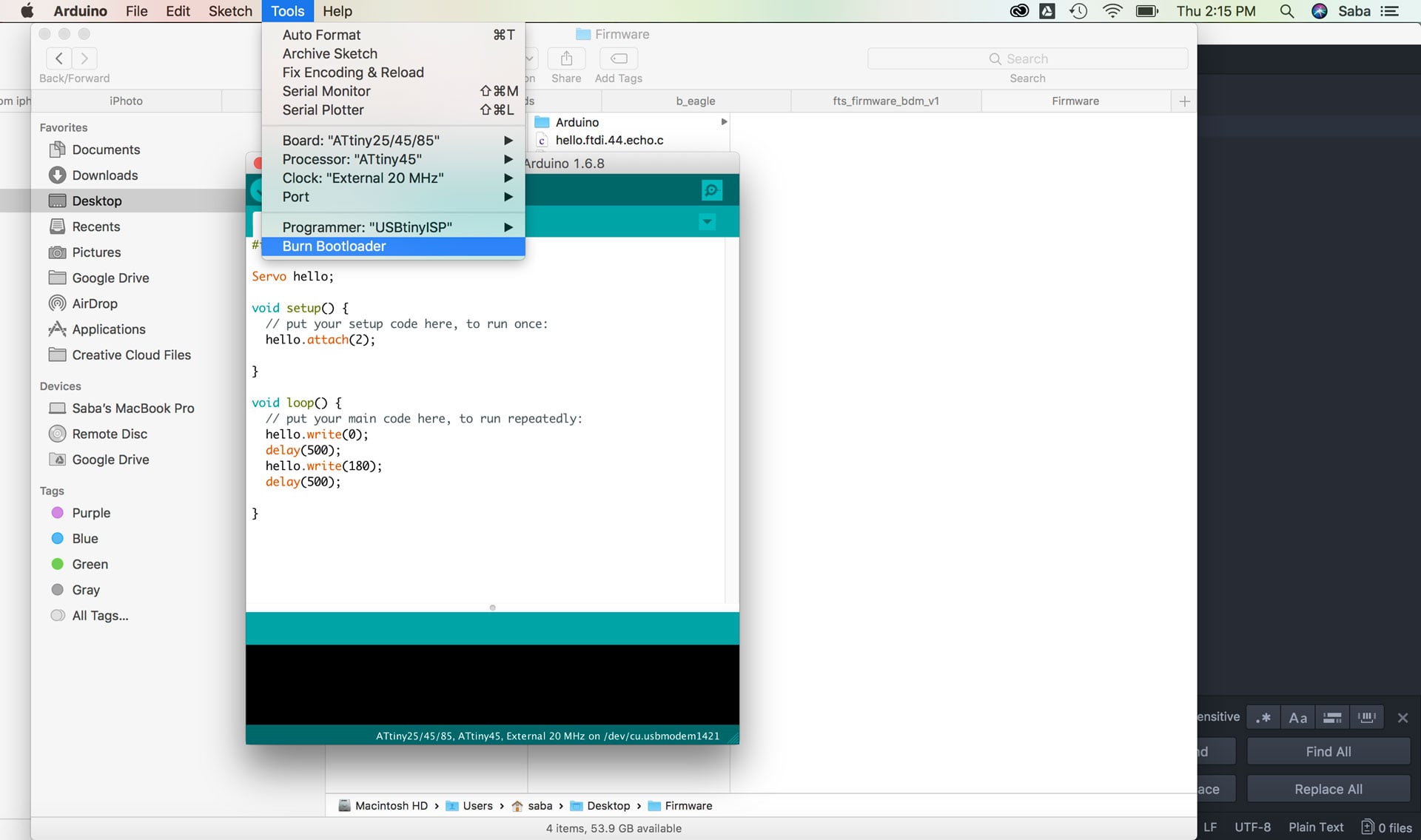
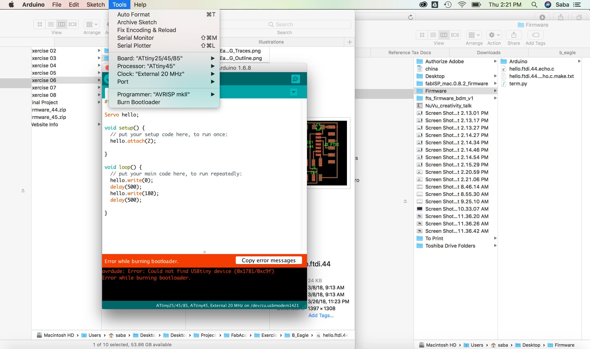
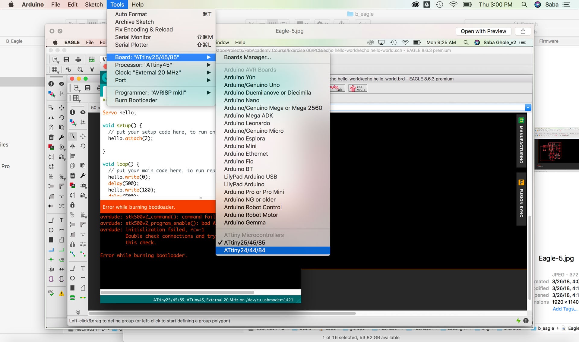
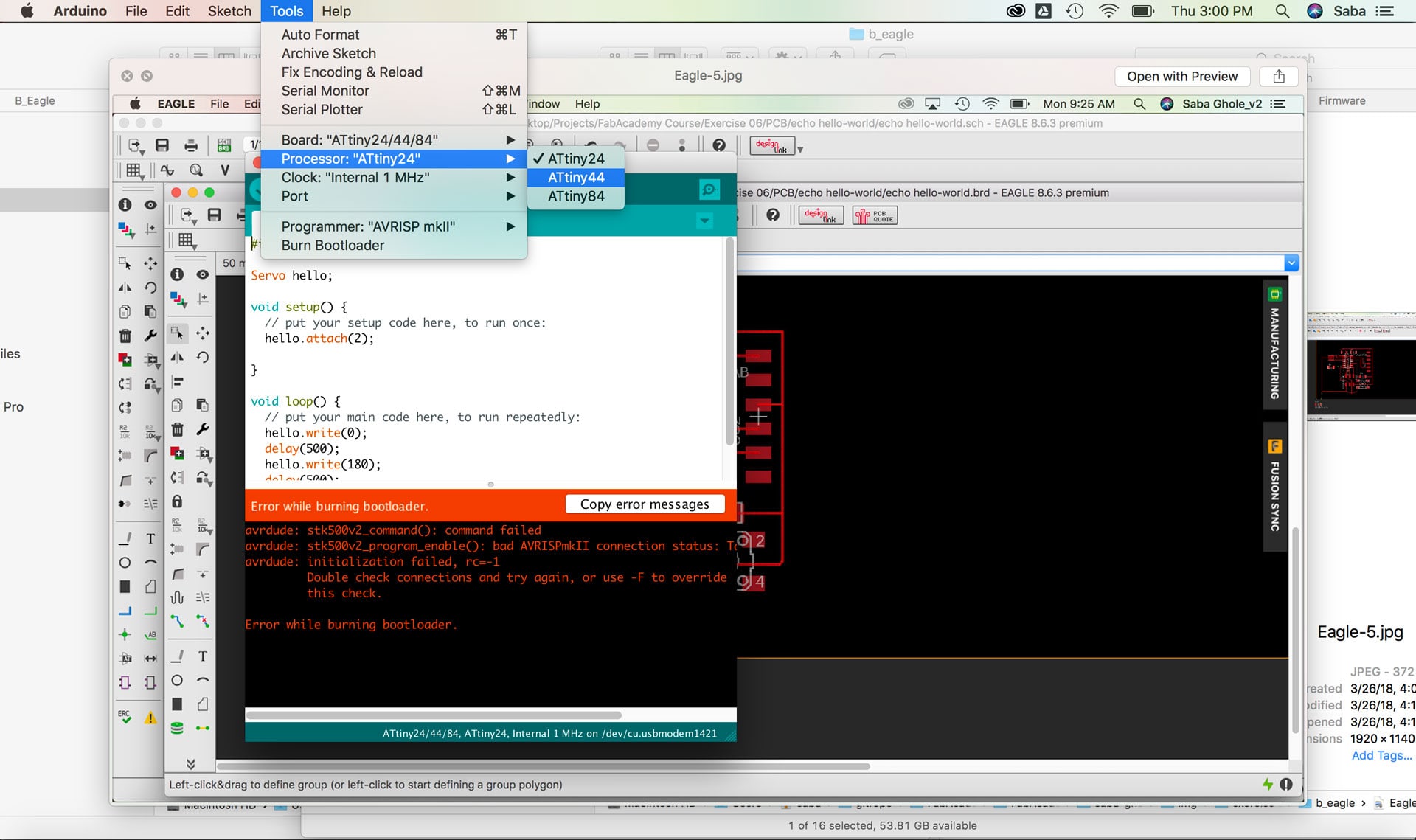
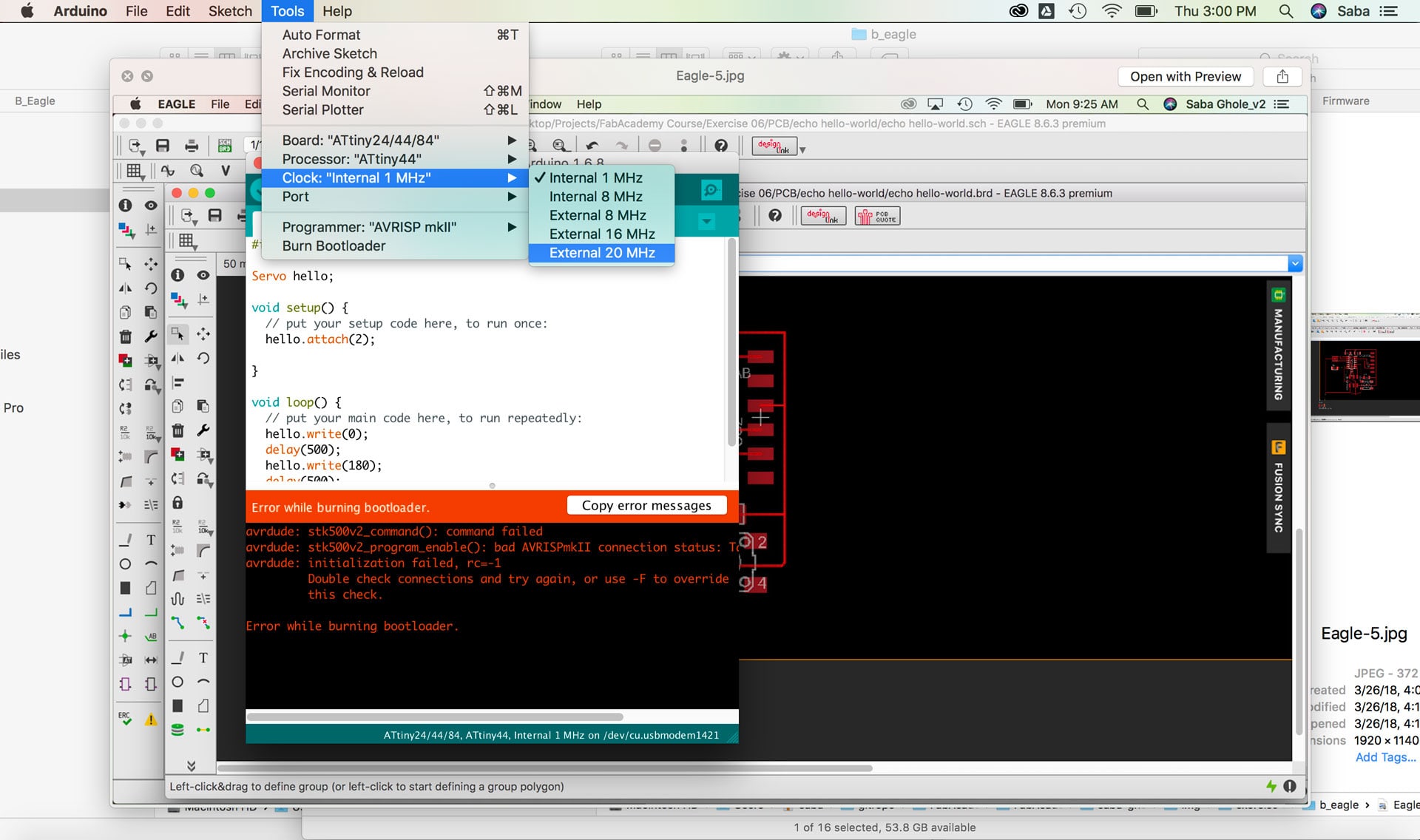
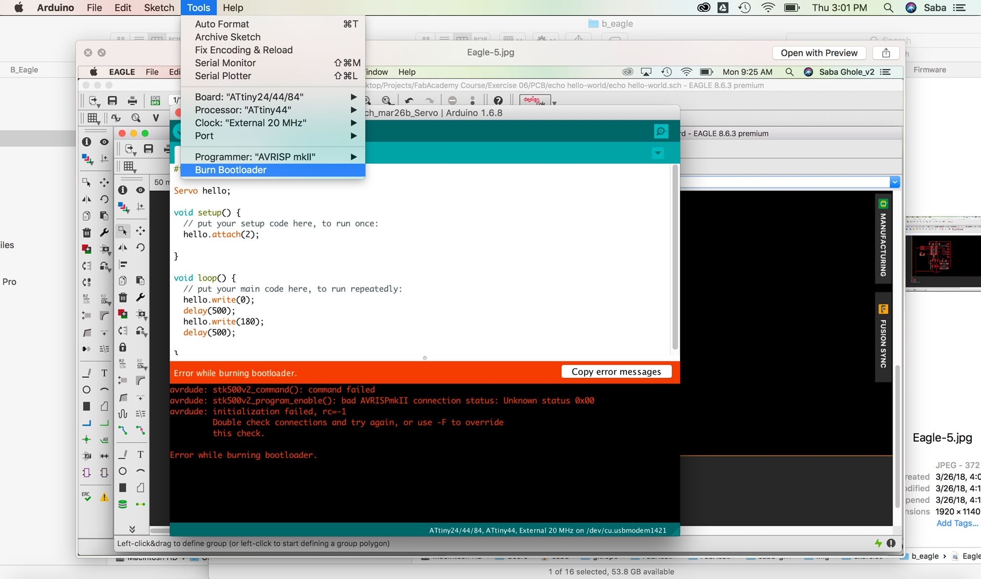
Under the tools menu, I updated the Programmer (USBtinyISP), Board (ATtiny24/44/84), Processor (ATtiny44), and Clock (External 40 MHz) and then ran the Burn Bootloader command which configures the fuse bits of the microcontroller. I only need to do this step once for the microcontroller. This doesn't actually burn a program code onto the board; I’ll still need to upload new programs using an external programmer in the future.
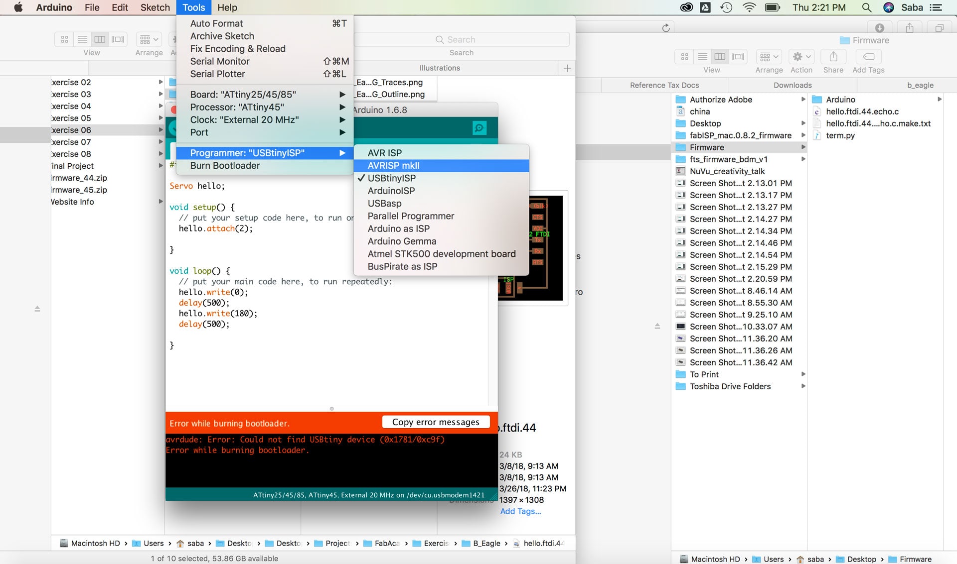
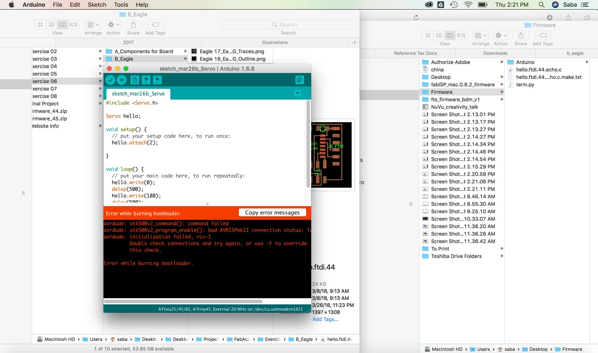
I received an error message: “Error while burning bootloader.” I decided to put my USBtinyISP to the side and try our in-house Programmer (AVRISP mkII)I to troubleshoot. I once again tried the Burn Bootloader command and still received an error message.
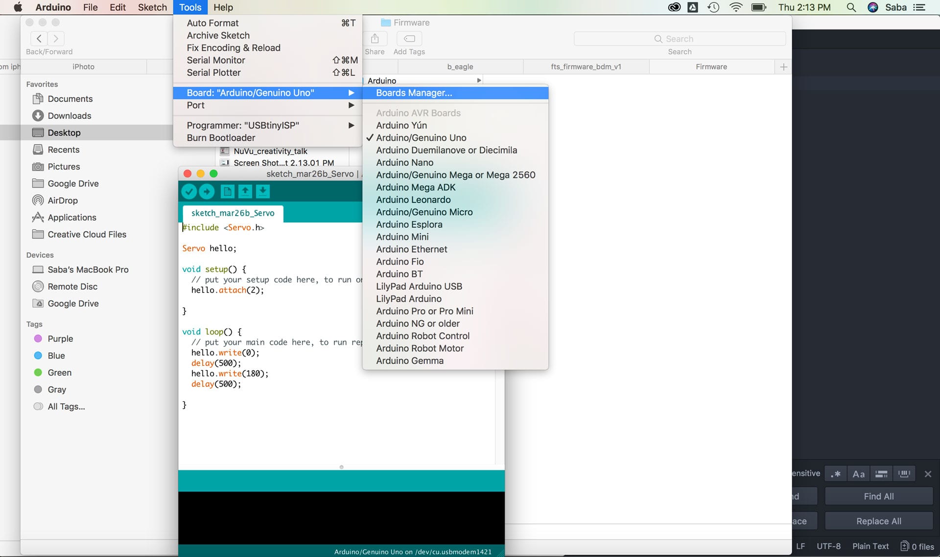
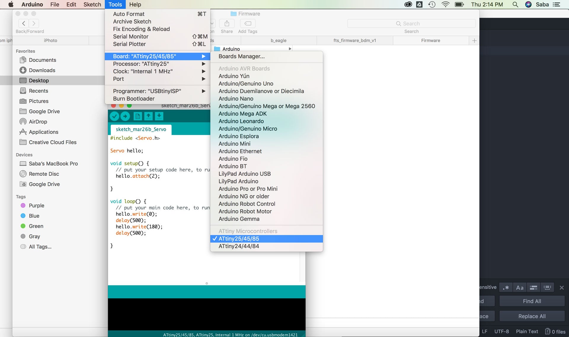
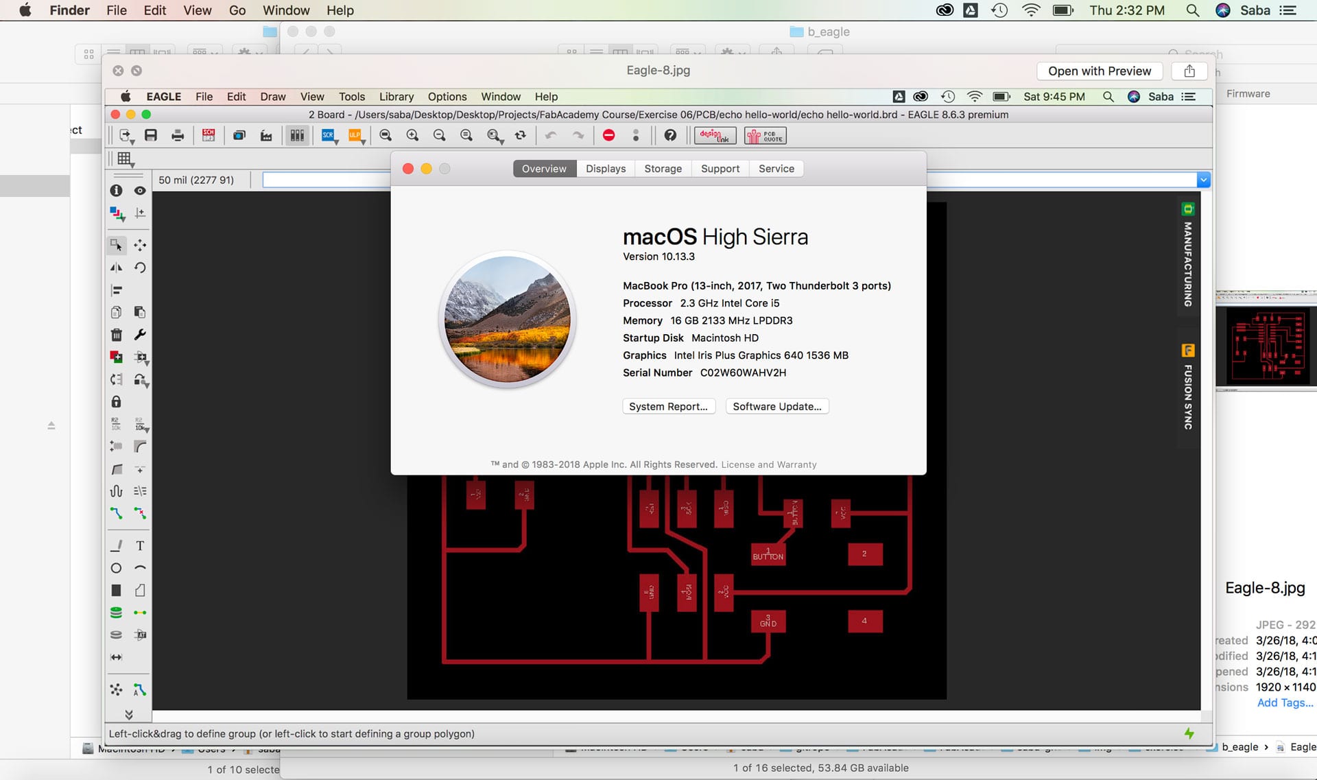
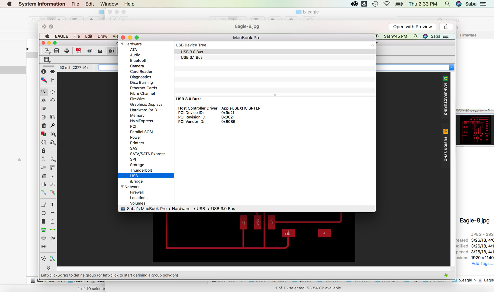
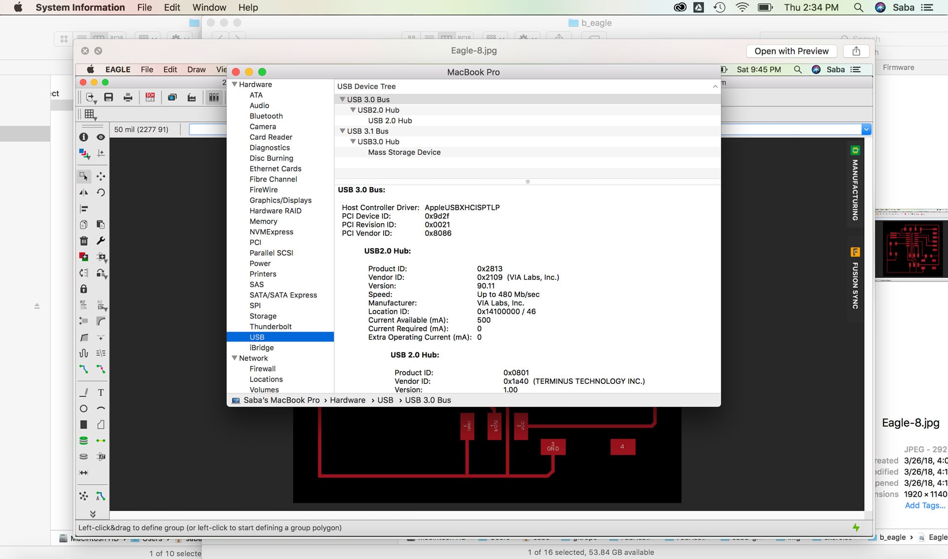
I then went to my System Report and checked under USB to see if my computer was reading my FabISP, and it wasn’t. Time for trouble shooting. I re-checked my settings in Arduino and realized that I had selected the wrong microcontroller and updated it to ATtiny44. And tried the Burn Bootloader command again.
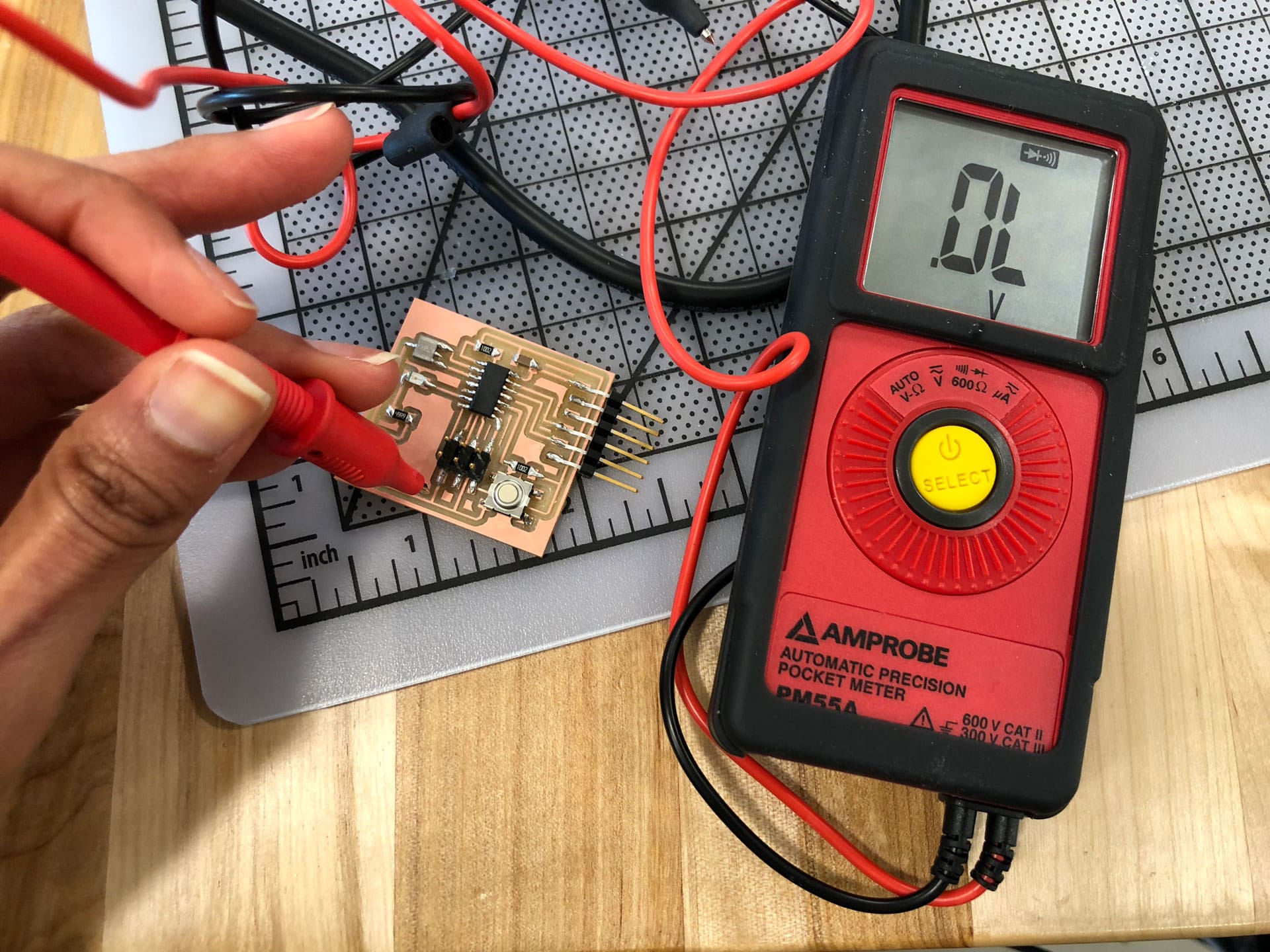
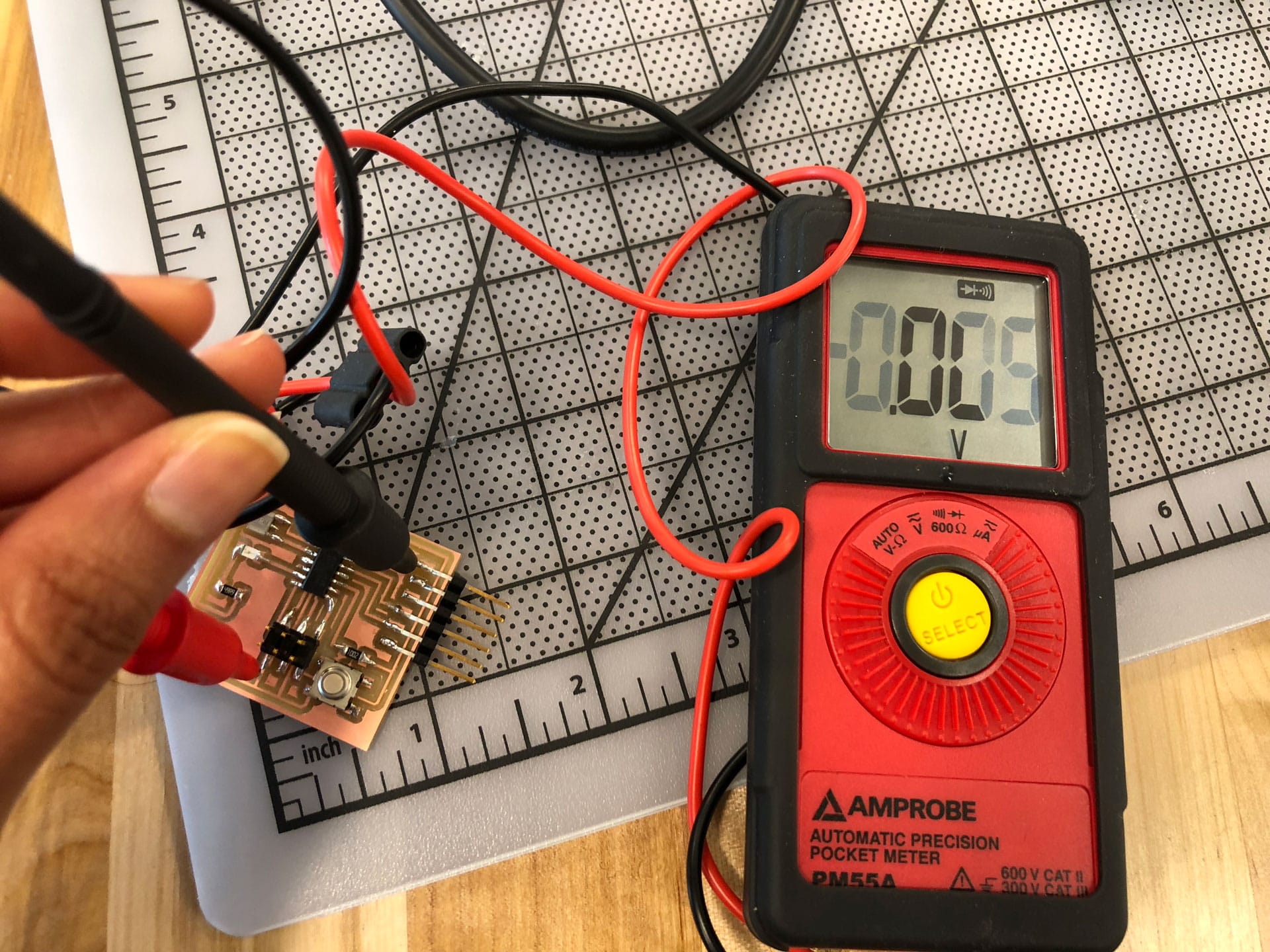
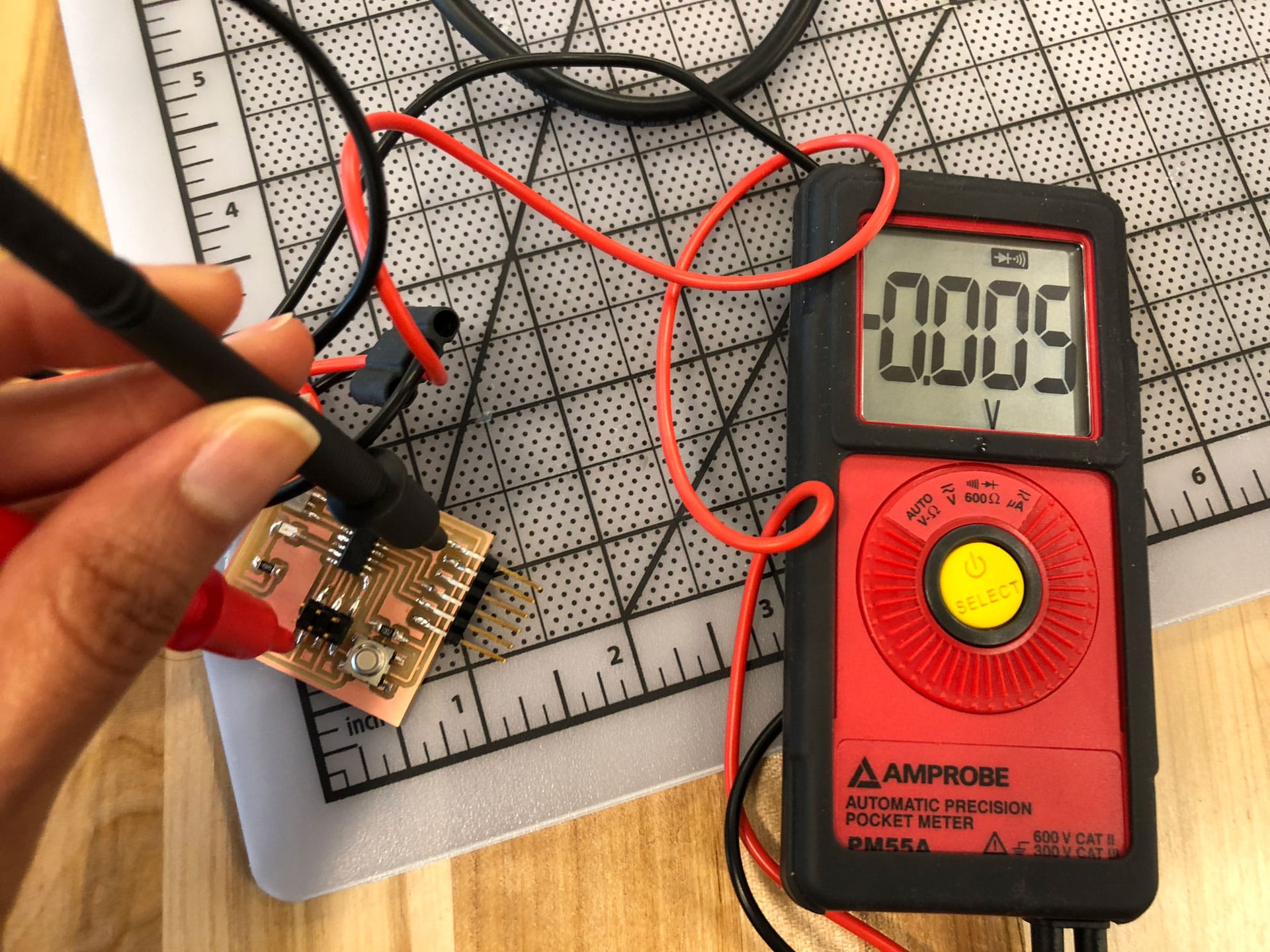
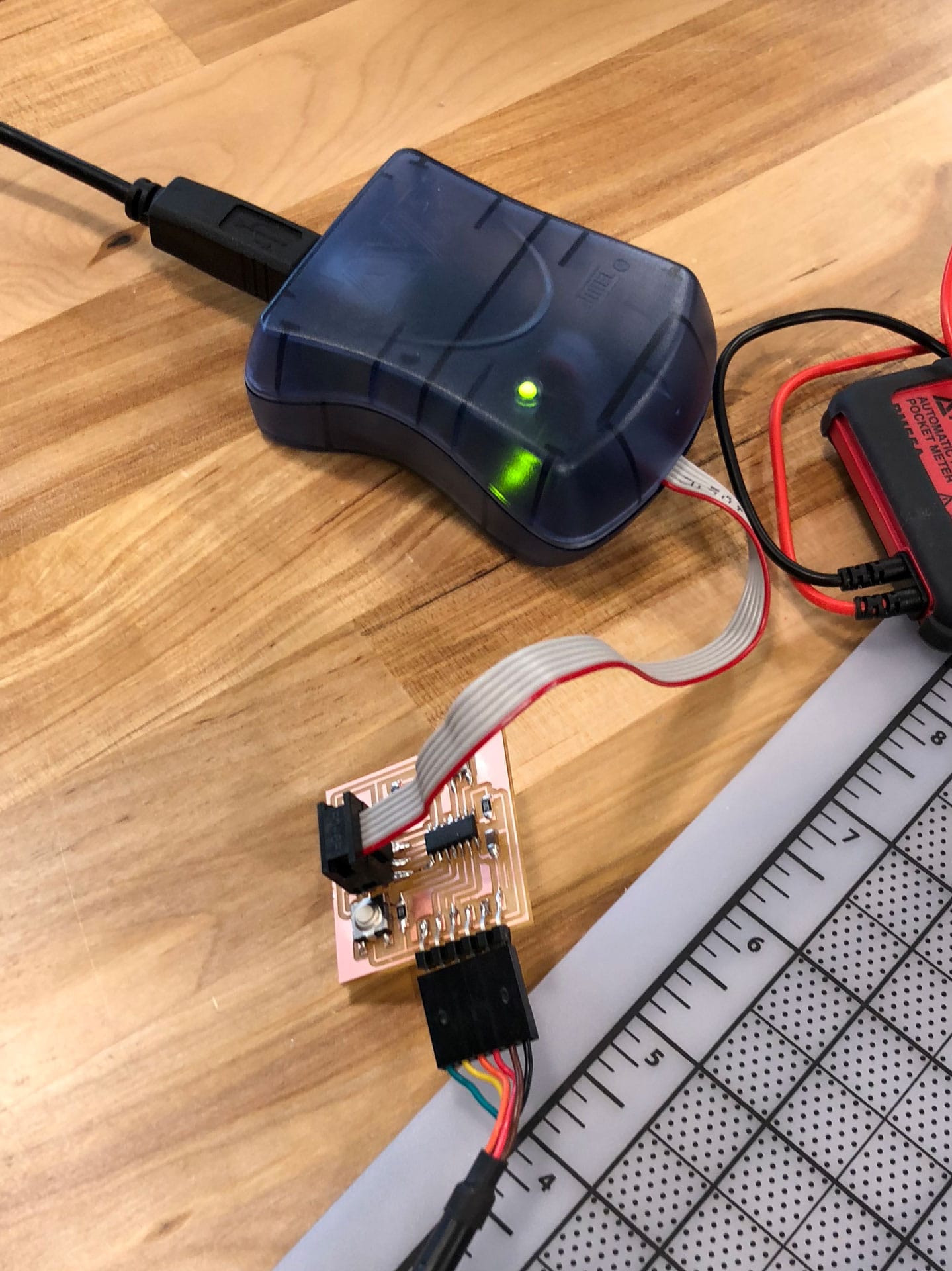
Clearly there was something wrong beyond the settings. I then checked the voltage readings on my board using a multimeter and realized that I wasn’t getting any power between my ground traces on a few components. Ok, we are getting somewhere now. It could be a soldering issue. I re-soldered my weak connections, and re-checked the voltage and viola! 5V reading between all my ground connections. I reconnected my board to the AVRISP mkII Programmer and both to my computer and viola! Green light on the Programmer suggesting that the Programmer and my board were communicating now.
I ran the Burn Bootloader command once more and finally success!!! A small tear of joy rolled down my cheek (ok...almost).
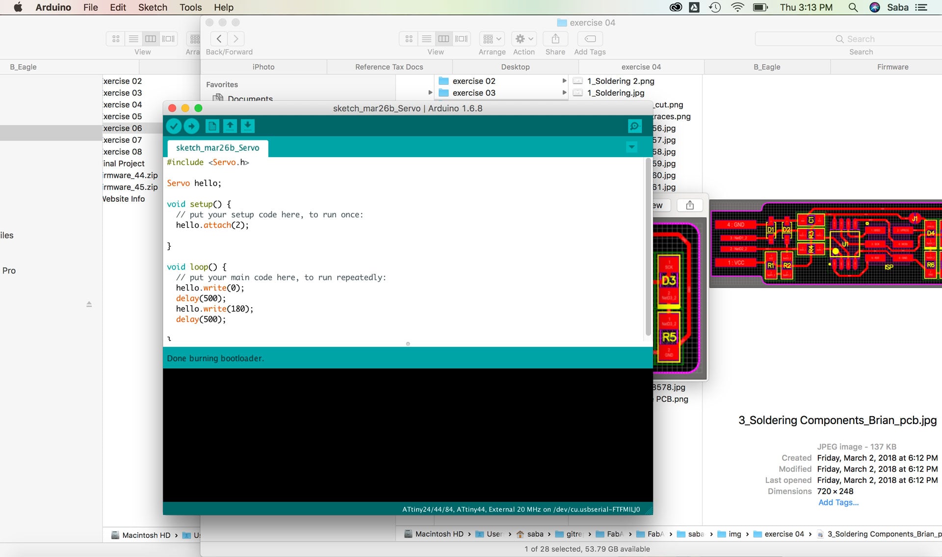
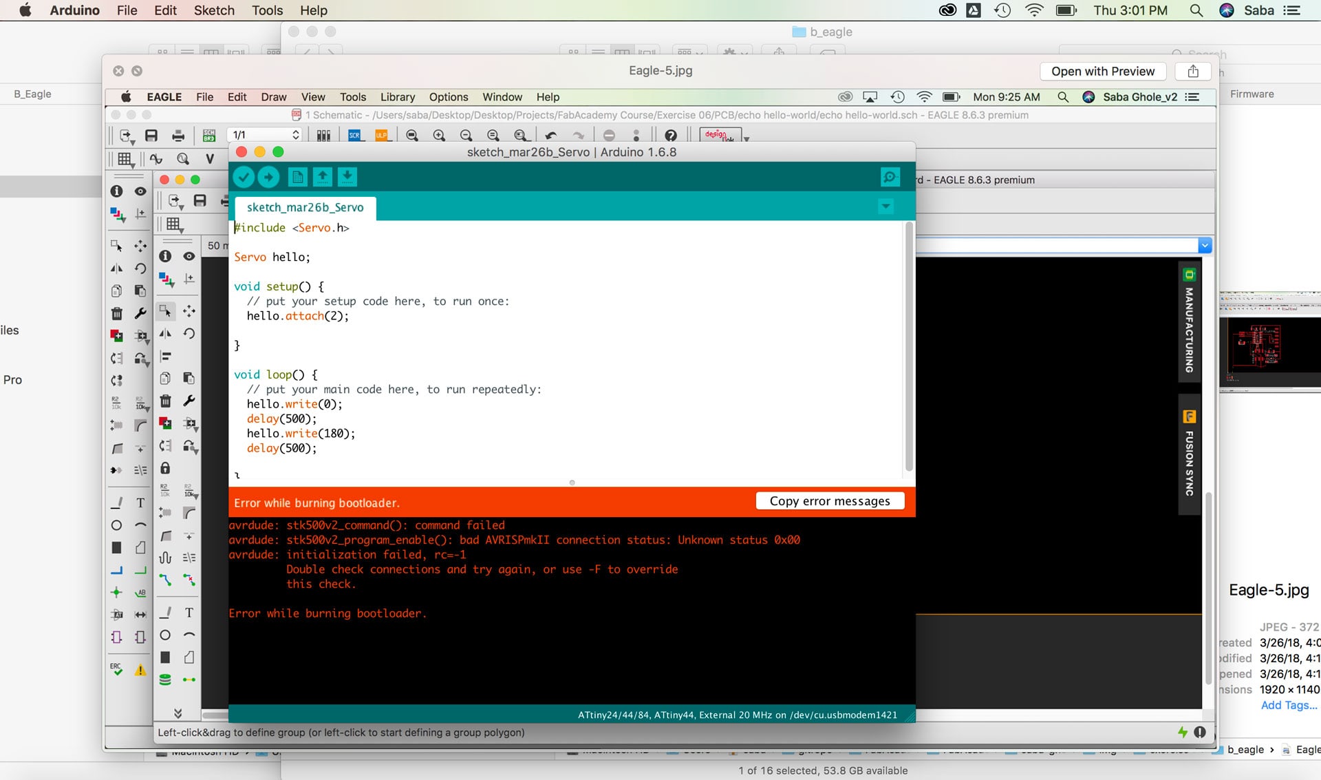
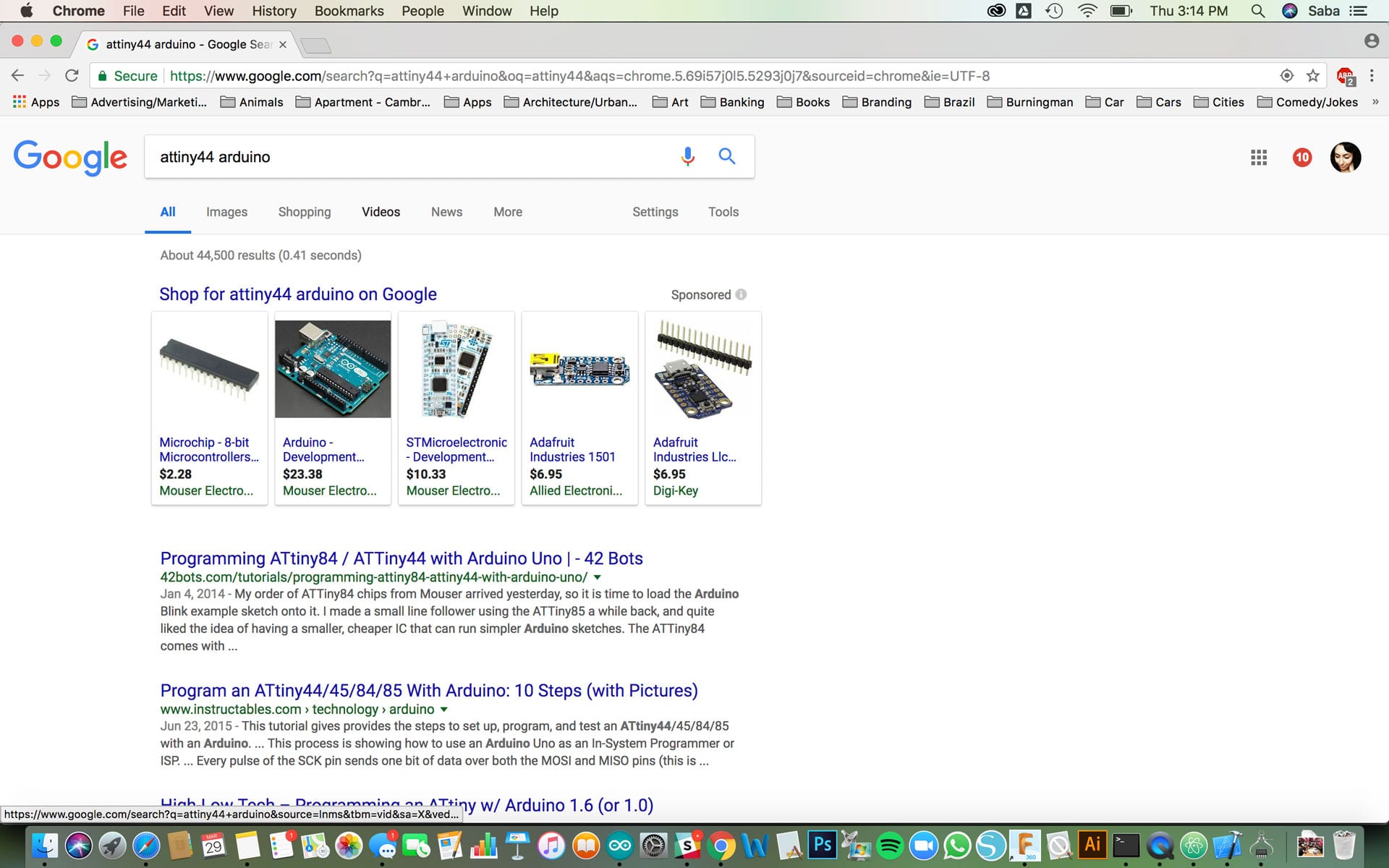
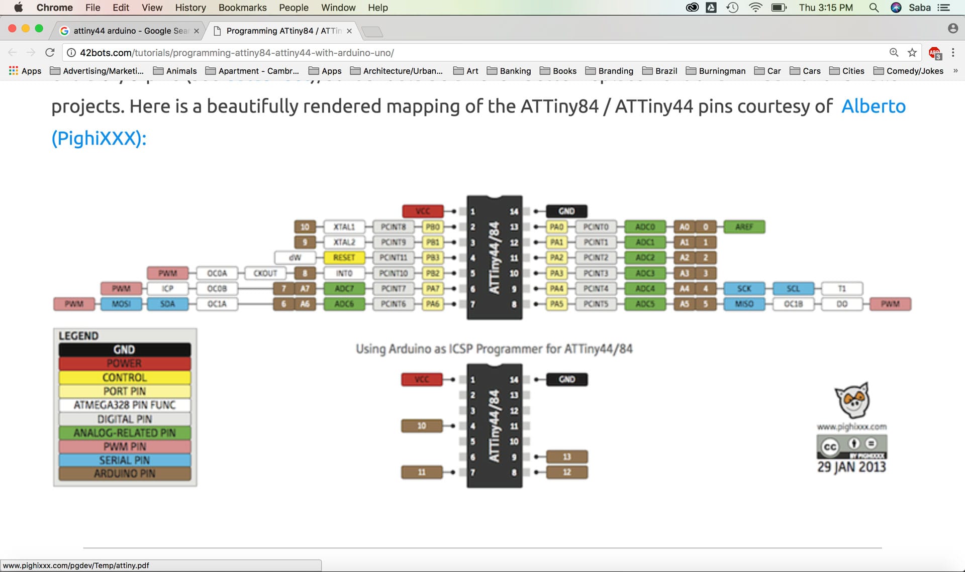
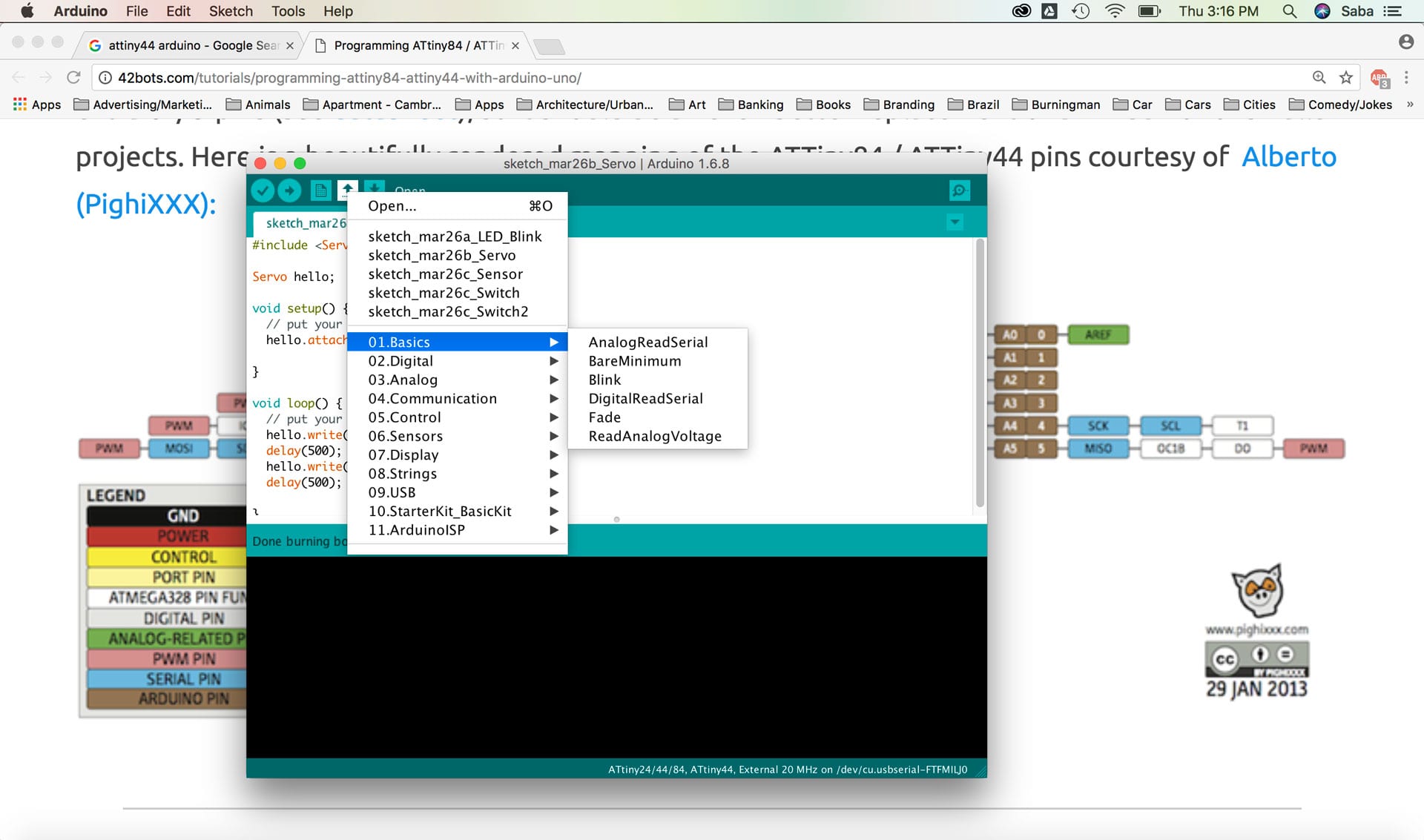
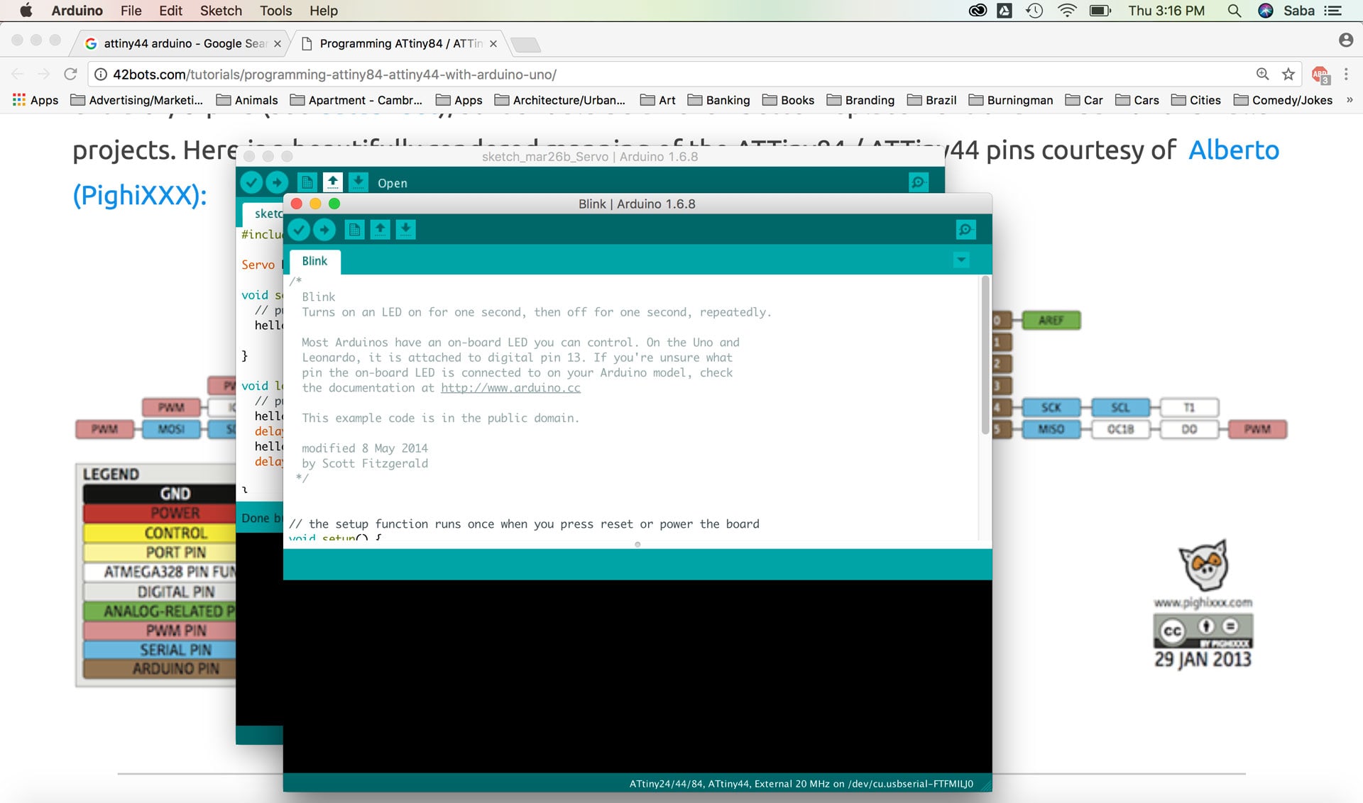
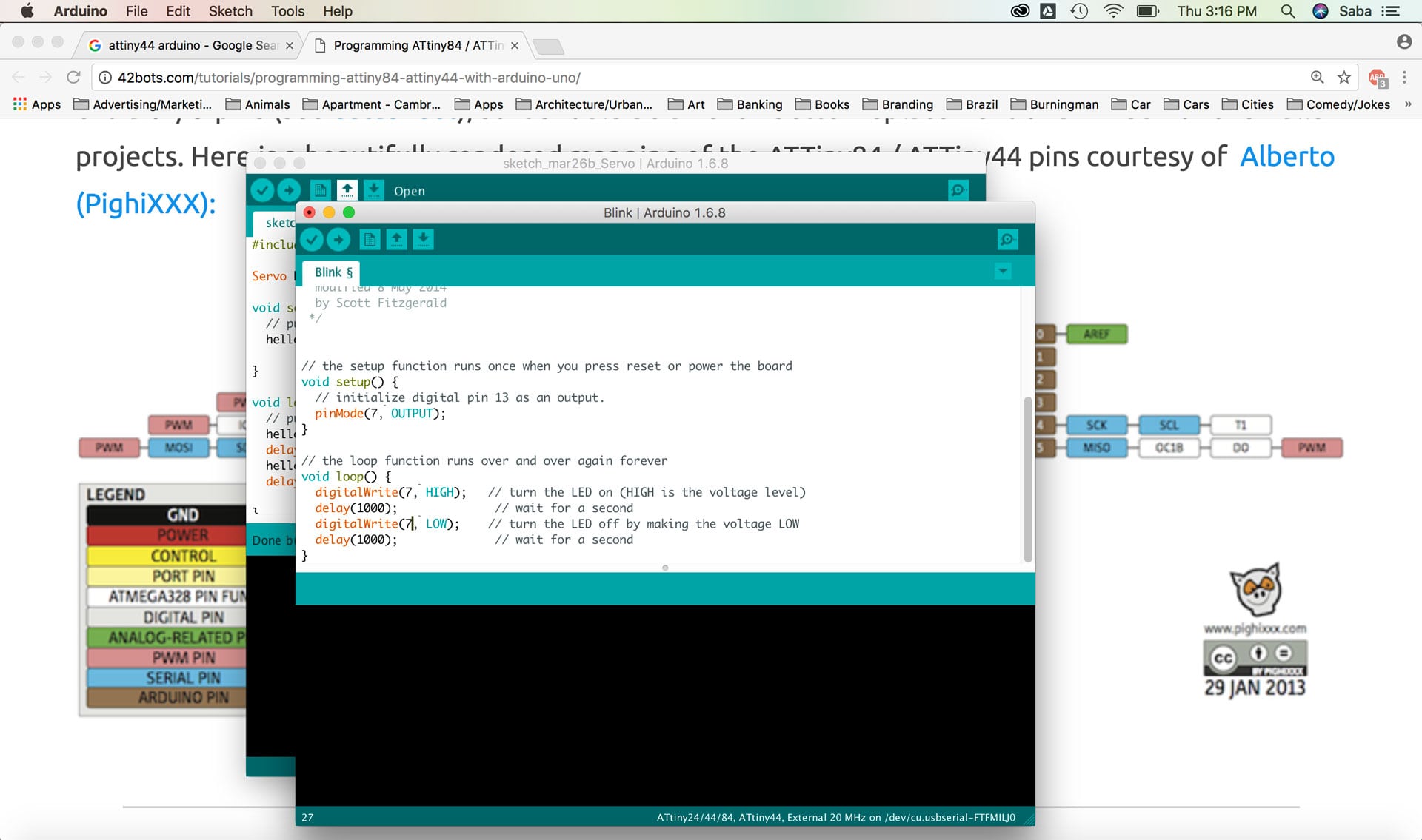
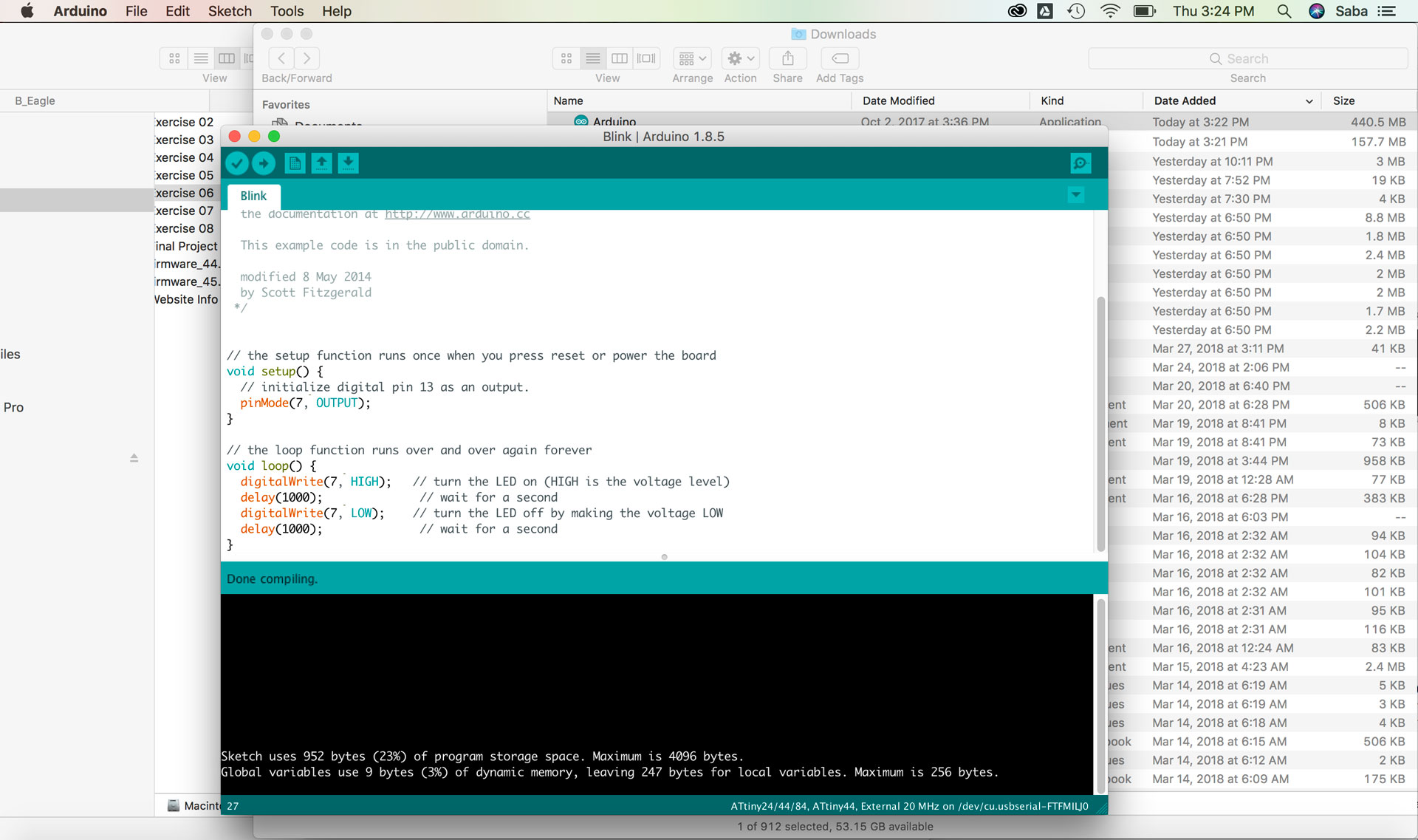
I then wanted to program the light on my board to blink to further test that everything was working well. I checked the Arduino datasheet online to see the pin translation between the ATtiny44 and Arduino pins, and saw that Pin 6 (which is connected to my diode) on the ATtiny44 maps to Pin 7 on Arduino. I updated these numbers in Arduino, verified the code and hit upload. Yessss! My LED was blinking!!
I also found a few of my colleagues blogs helpful through this week's assignments, including:
Download the Echo Hello-World Board, Traces, Arduino LED Blink Code, and Fab Libary.
Click to download Eagle Echo Hello-World Board .sch file.
Click to download Eagle Echo Hello-World Board .brd file.
Click to download Arduino LED Blink .ino file.
Click to download Fab Library for Eagle .lbr file.
Click to download Fab Academy Design Rules Check .dru file.