WEEK 11
OUTPUT Devices
Assignment:
- Add an output device to a microcontroller board you'ved designed and program it to do something
Software(s):
- Arduino
- Adobe Illustrator
Skill(s):
- Electric Design
- Electrical Prototyping
- Programming
QUICK RECAP: In Week 10 I built and programmed my Barduino along with a peripheral thermistor board to read and record temperature. My next addition to the board is adding a peripheral RGB board that will react to the change in temperature. Ideally I want the RGB to turn blue if the temperature drops a certain amount and to turn red if the temperature rises pass a certain amount. In this week I plan to design, build and program my Barduino to do this.
SHEMATIC DESIGN
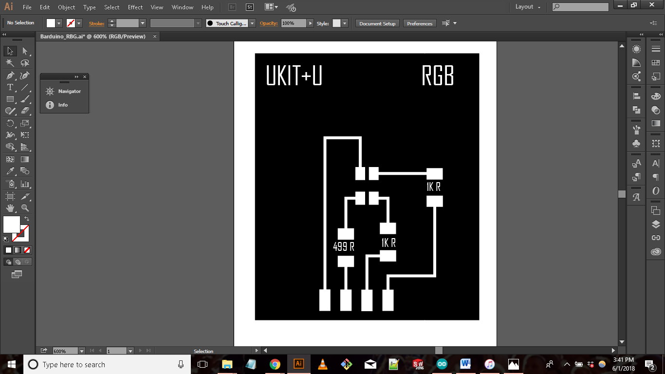
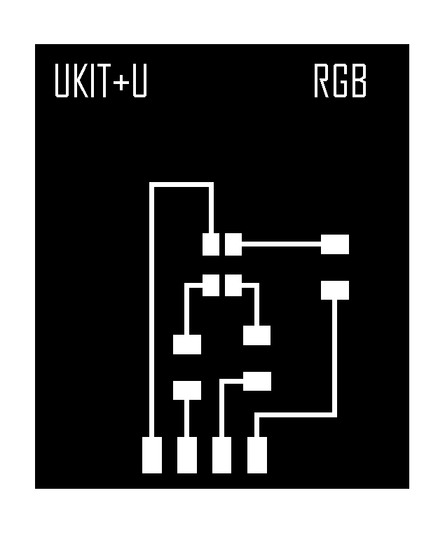
For this week I wanted to create an RGB board that reacted to the change in temperature. For this board I referenced the board I made in Week 8 (http://archive.fabacademy.org/2018/labs/fablabdassault/students/oyedotun-ajweole/exercise08.html) and stripped it down. The new board no longer needs its own microcontroller.
- 1 x RGB LED
- 2 x 1k Resistors
- 1 x 499 Ohm Resistor


MILLING & STUFFING
Milling and Stuffing went without a hitch
PROGRAMMING
Programming the board was pretty straight forward. During week 10, I programmed my board to successfully read temperature. All that is left for me is to do is program the board to react to the change in temperature. In Week 8 I wrote a simple code that blinked a RGB LED between red, blue and green. I took the code I wrote in week 8 and added to my Barduino code. I used “if” “else” logic functions to set parameters so the board knows how to react to specific situations.
int Temperature= 1; //determine the type of data and signal the pin
float sensorValue;

int bluePin = 5;
int greenPin = 6;
int redPin = 7;

// the setup function runs once when you press reset or power the board
void setup()
{
  // initialize digital pin 13 as an output.
  pinMode(13, OUTPUT); // Make pin13  an output pin
  pinMode(bluePin,OUTPUT);
  pinMode(redPin,OUTPUT);
  pinMode(greenPin,OUTPUT);


  Serial.begin(9600);
  Serial.println ("Hello I am Working");

 }

// the loop function runs over and over again forever
void loop() {

//QUICK NOTE:
//0 = open
// 255 = close
//Since this is a common anode rgb the numbers are reversed. When pin is at 0 or ground that is when the highest brightness comes through for the pin.
//Color Settings:

// RED: setColor(255,250,0);
// GREEN: setColor(250,0,250);
// BLUE: setColor(0,250,255);


sensorValue = analogRead(Temperature);              // Read and store the analog input value coming from the temp sensor pin

double TempC, TempF, T;                                 // Define the variables to show the temperature data
double R = 10000 / (1023.0 / sensorValue - 1);  // Steinhart - Hart    /// Resistance = 10 k ohm     /// (2^10 = 1024)
double L = 10000 / R;                           // L = R0/R // 10000/R = ReferenceResistance/ NominalResistance = ResistanceInNominalTemperature25oC)

  //T = 1.0/((1.0/(25.0 + 273.15)) + (log(R0/R))/3750))
  //T = 1.0/((1.0/(25.0 + 273.15)) + (log(L))/3750) * log(L))
  T = (0.0033540164 + 0.00026666666 * log(L));    // Steinhart-Hart 1/T=1/T0 + 1/B*ln(R0/R)
  T = 1/T;

  TempC = T - 273.15;                              // To get Celcius degrees Temperature = T - 273.15 (Kelvin degrees)
  TempF = TempC * (9.0/5.0) + 32;                 //Convert Celcius to Fahrenheit

  Serial.print("Celsius ");                   // To print information to the Serial Monitor
  Serial.print(TempC);
  Serial.print(" C ");
  Serial.print("  |   ");
  Serial.print("Fahrenheit ");
  Serial.print(TempF);
  Serial.println(" F ");


if ( TempF > 85 ) {
setColor(255,255,0); //if Fahrenheit is higher than 85 degrees turn  RGB red
}

else if (TempF < 70)
{
  setColor(0,255,255); //if Farhrenheit is lower than 70 degrees turn RGB blue
}
else{
  setColor(255,0,255); //turn RGB green if both above settings are met
}

delay(500);


  //digitalWrite(13, HIGH);   // turn the LED on (HIGH is the voltage level)
  //delay(1000);              // wait for a second
  //digitalWrite(13, LOW);    // turn the LED off by making the voltage LOW
  //delay(1000);              // wait for a second
  //digitalWrite(5, HIGH);
  //delay(1000);
  //digitalWrite(5,LOW);
  //delay(1000);

}


void setColor(int blue, int green, int red)
{

digitalWrite(redPin, red);
digitalWrite(greenPin, green);
digitalWrite(bluePin, blue);
}
QUICK NOTE: I realized when I uploaded my original RGB blink code; my RGB would not blink green, red, and blue. Instead it would blink a lime green, yellow, and violet. After some research I found out why. Initially I was programming the RGB to work like a normal LED. I would set the pin HIGH to turn the LED on and set it LOW if I wanted to turn the LED off. RGBs work different. RBGs work by controlling the brightness of each of the red, green, and blue parts of the LED separately, making it possible to mix any color you like. The way to do this in code is to write a function that takes three arguments, one for the brightness of red, green and blue. Each argument will be on a scale from 0 to 255, with 0 being off and 255 being maximum brightness.
Ex: setColor(255, 255, 0) = RED
or
setColor(255,0,255) = Green
Now it is time to test run my circuit. At room temperature my sensor was reading temperature around ~76 F. So I used the threshold of 70-85 F as the default settings. I then told the board if the sensor reads temperature to below 70 F turn the RGB blue and if the readings is above 85 turn the RGB red. For my cold source I used an ice pack. For my heat source I used my fingers and pinched the sensor.
The board was is a success! I am happy with the progress I am making. As far as my final project the next steps will be to add a second thermistor and the heating pads to my board.
FILES:
RGB Board:
RGB Illustrator File
RGB Traces
RGB Shape