WEEK 5
3D Printing and Scanning
Assignment:
- Test the design rules of your printer(s)
- Design and 3D print an objet (small, few cm) that could not be made subtractively
- 3D scan an object (and optionally print it)
Software(s):
- SolidWorks
- 3DWox Software
- PreForm
Skill(s):
- Drawing
- Product Design
- 3D-Aided Design
- 3D Printing
- Living Hinges
- Prototyping
- Sindoh's 3DWox DP201
- FormLab's Fuse 1
For this week’s assignment I wanted to create 3D eye glasses with topology designs that would make it hard to manufacture through subtraction . Ive had an affinity for luxury glasses and thought it would be cool to create my own version through 3D printing.
3D PRINTING PT. 1
| Design & Solidworks |
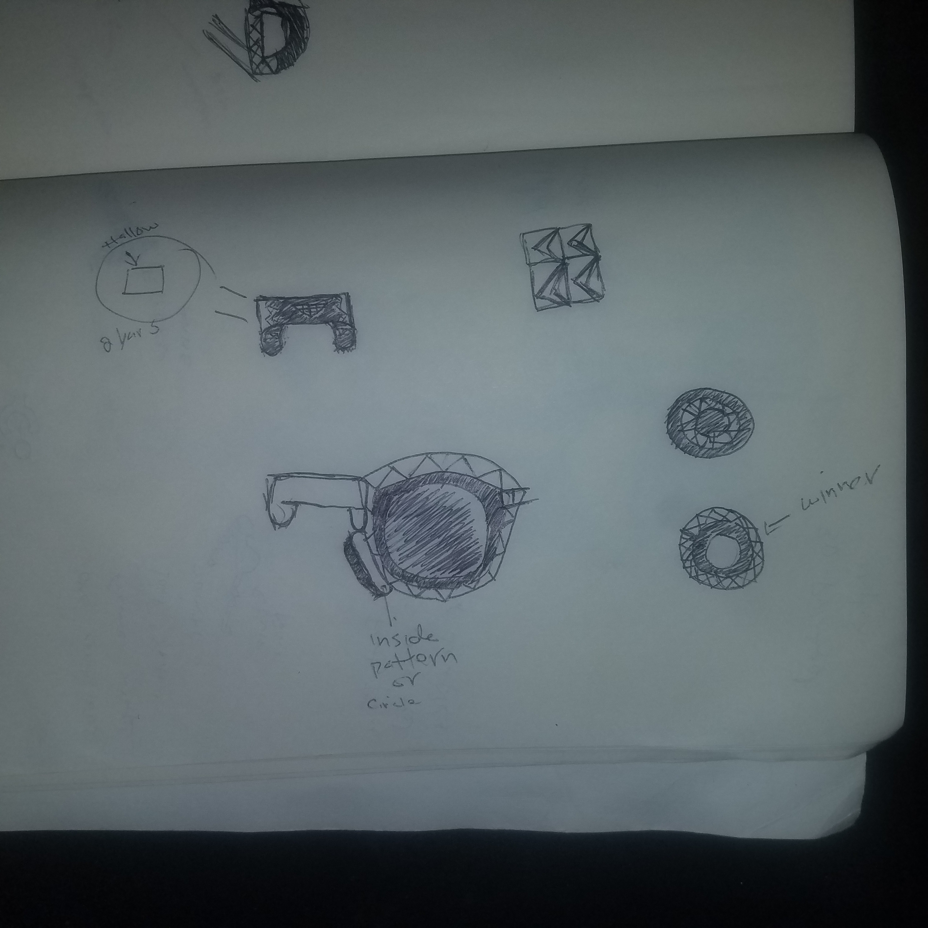
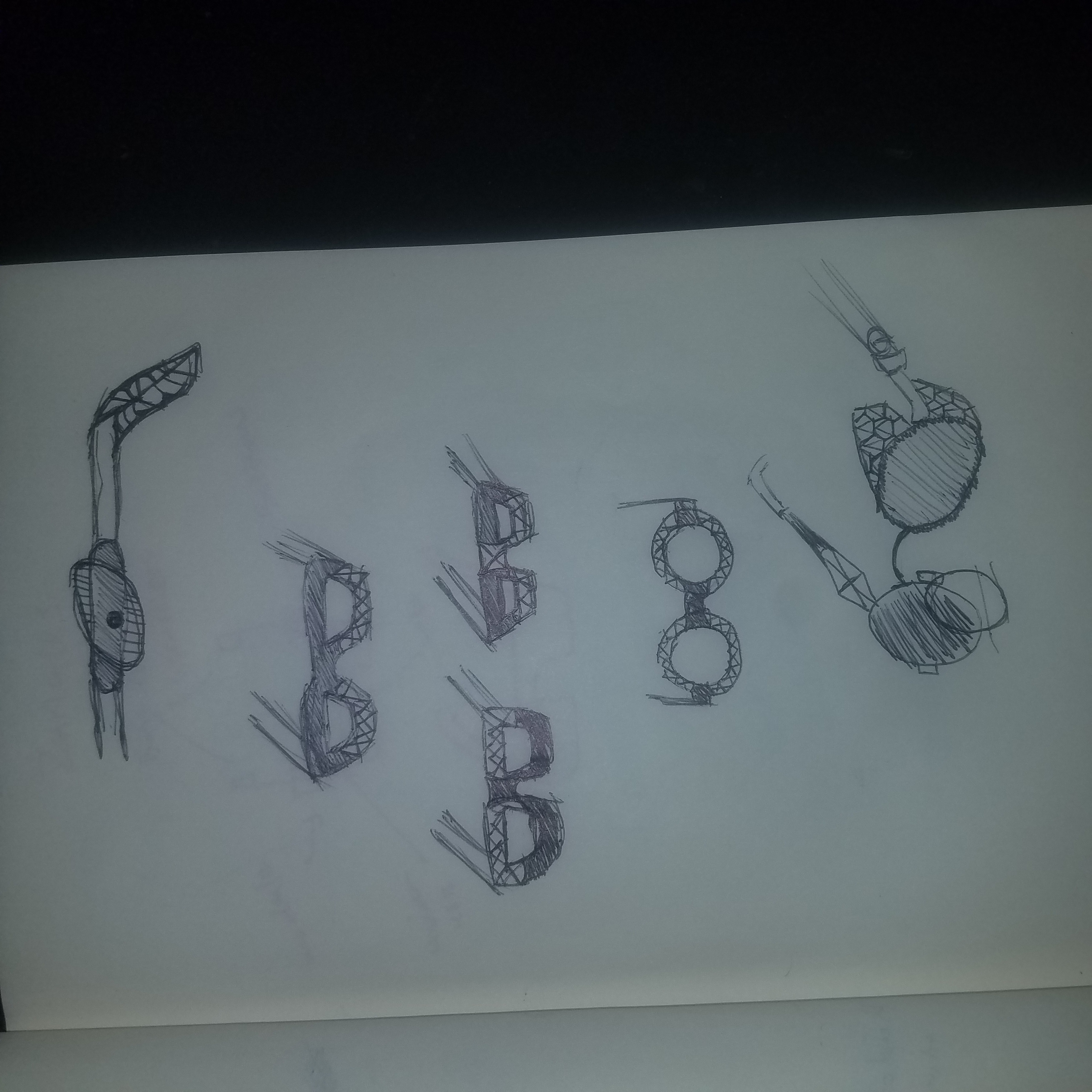
As usual I start my design process with a variety of sketches in order to get a feel and direction for my design. Once the sketch phase is done I move the design process to SolidWorks. Constructing the glasses was slightly tricky. This is my first time designing eyewear, so I decided it would be a good idea to use my own pair of glasses as a reference.
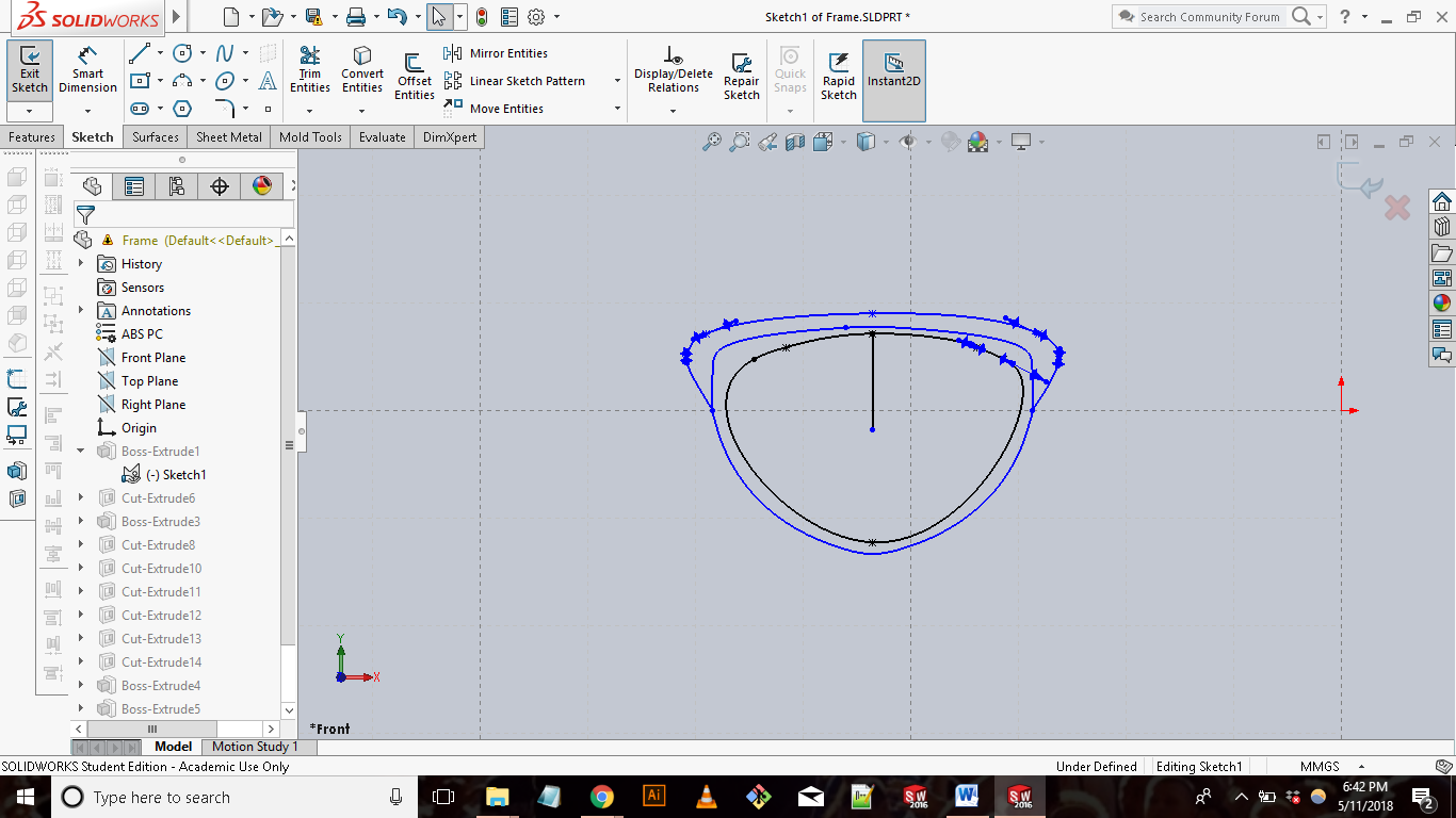
Next step is to dive into creating the 3D model of my glasses. As usually SolidWorks is my infinity gauntlet. My approach to designing the glasses was to break the process down into 2 parts, the frame, and left/right temples. I first started with designing the frames. I began the frame by creating a sketch of the left lens. Using the spline tool I created an oval like shape, and then added the shape of the actual frame around the lens. Once I was satisfied with the shape I then used the extrude tool to create a solid. I thought it would be cool to add some design to the frame to give it some character. So started sketching a repeating pattern across the top of the frame, then used the extrude cut tool to cut out the pattern across the frame.
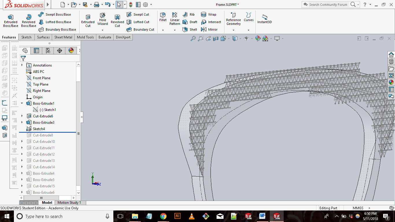
[NOTE:Honestly in hindsight, the design across the top of the frame wasn’t the best lol (smiley emoji)
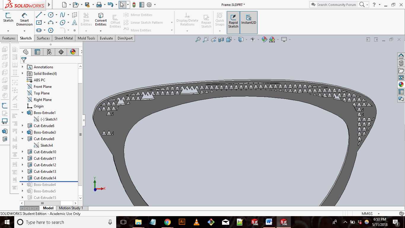
The next step was creating half of the bridge and place for the left and right temples to connect to. I then mirrored the left lens to create the right and the frames were done. Now on to the temples.
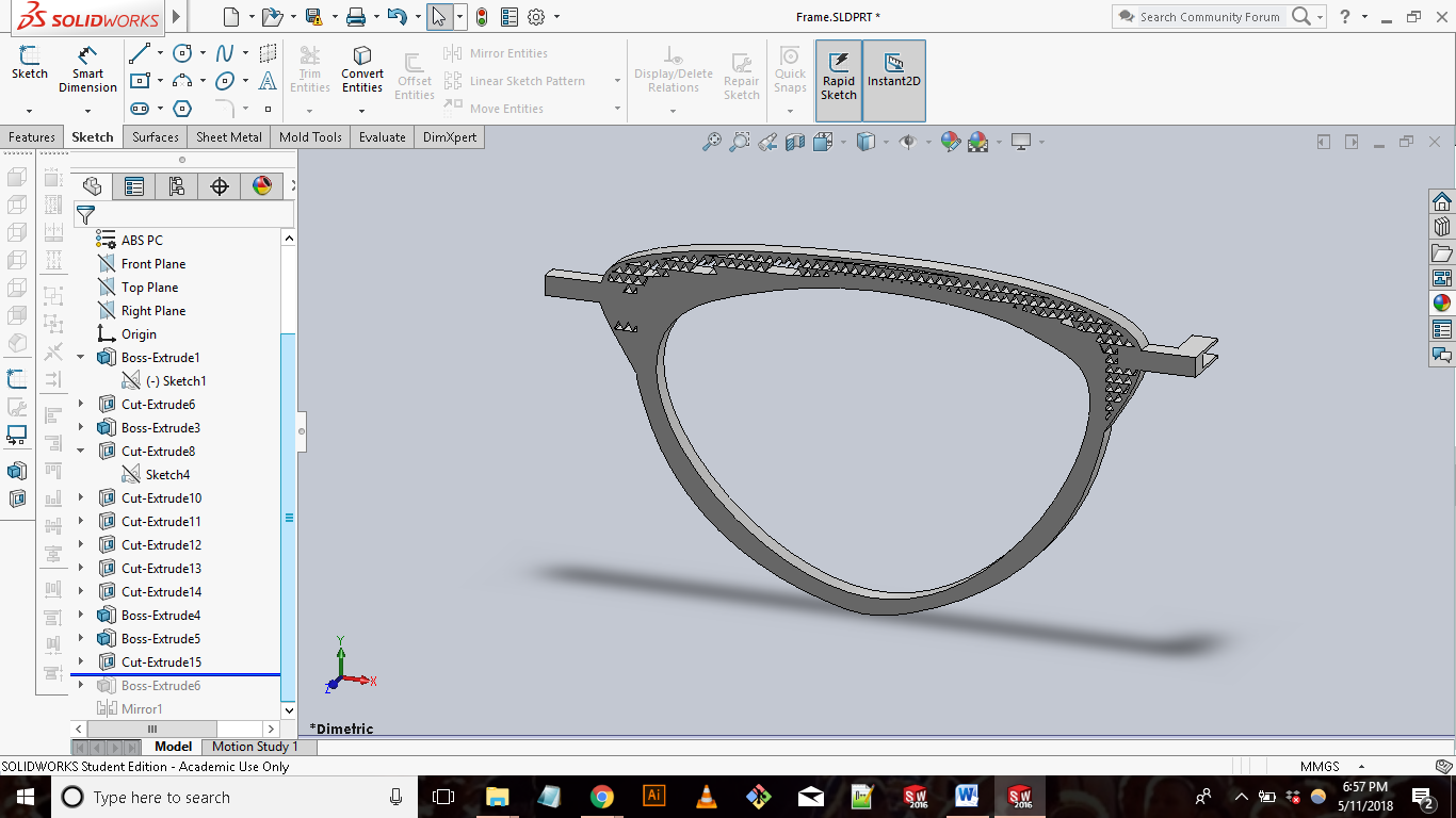
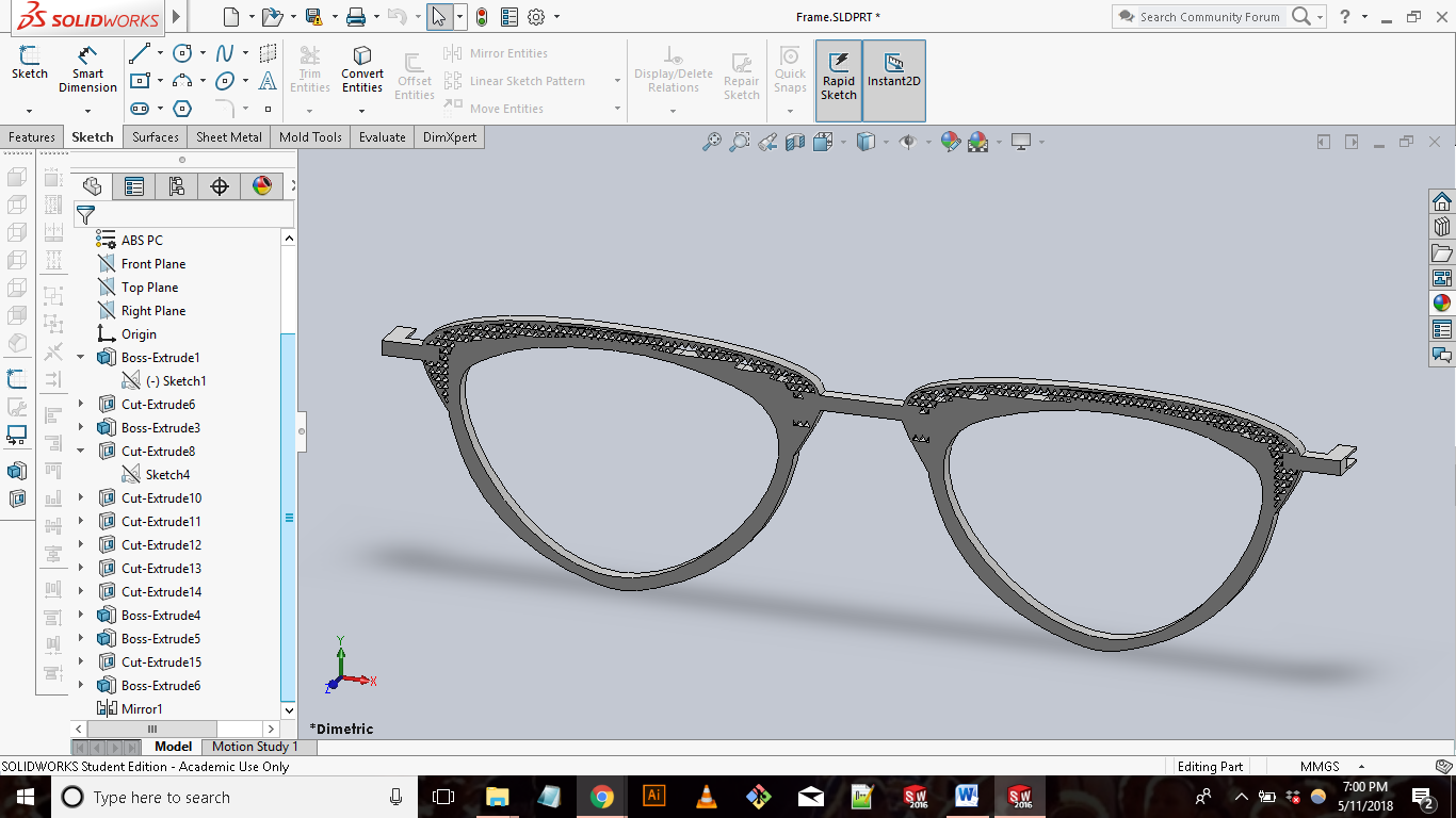
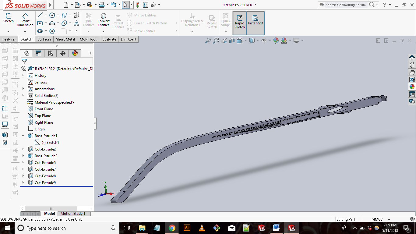
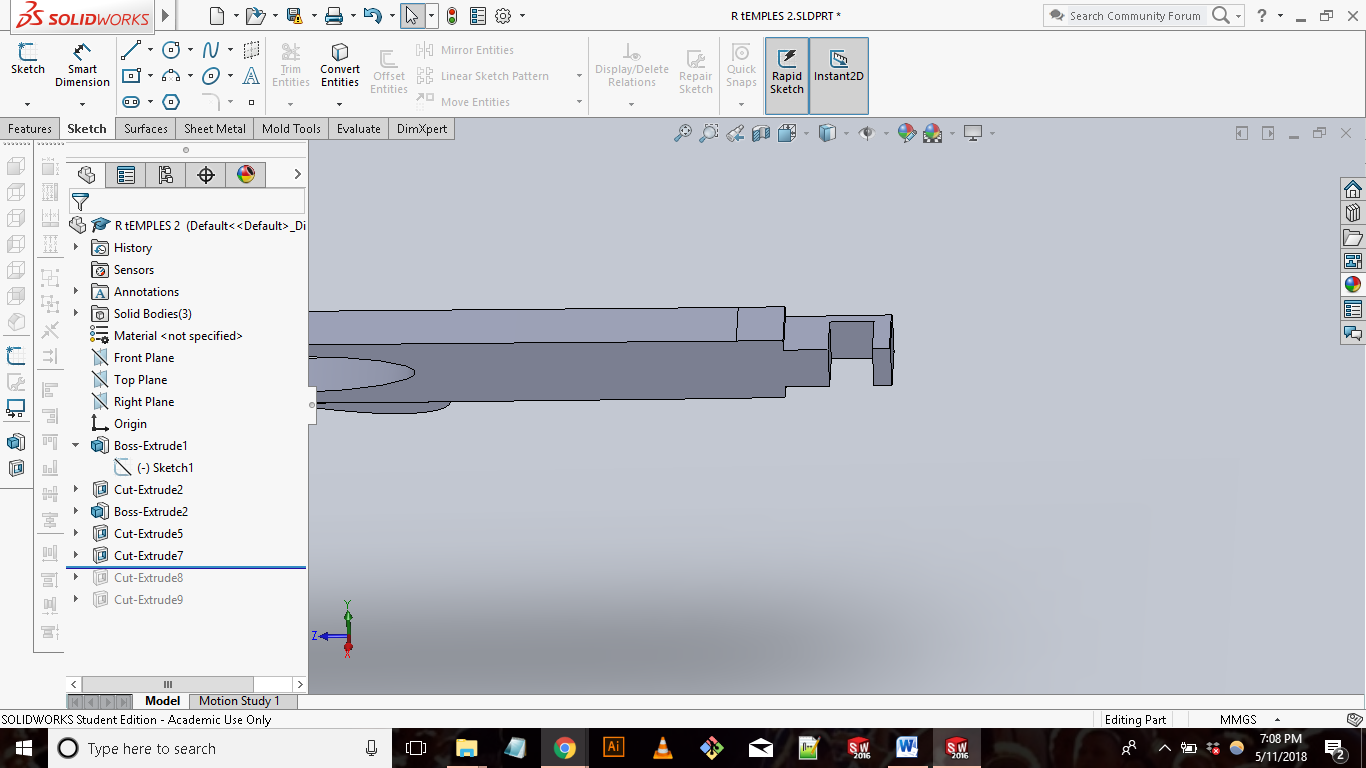
The temples were pretty straight forward. I started by creating a sketch on the right place. Switching between the spline and line tool, I was able to create the shape for my part. I then extruded the sketch to make it solid. When I was thinking about how to connect the temples to the frame I came up with a hook idea. The temples would hook onto a rod on the frame which will allow movement in the x-axis and prevent movement in the y. At the time I thought this was a good idea. After making the hook I then added a few design aspects to the temple to make it match the frames.
|Printing|
MFor me to be able to print my model it is absolutely essential for me to first convert my file into an STL file. Usually this is done using the 3d printer’s native software or free software that specifies in this. For me I was able to export my file directly as a STL through Solidworks. My first go at printing the glasses was with the Makerbot Replicator 5th Generation 3D printer with standard ABS. I loaded my STl into the Makerbot software, used the “generate supports” tool and printed the file. The print didn’t take long, around 5 hours but the print came out pretty bad. The temples were to thin and broke when I tried to remove them from the printing bed. The dimensions I used were realty off which made the frames really huge and the temples tiny. Reviewing the disaster it was easy for me to recognize the problem lied in my design and not the printer. Back to my design!
3D PRINTING PT.2
|Design|
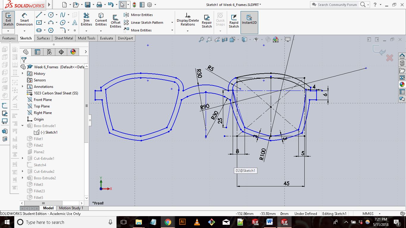
There were a few takeaways from my first attempt. The first takeaway was that my dimensions were completely off. This time I measured two pair of glasses instead of one. I then used the average of both as my dimension reference. In my SolidWorks model I was also careful and made sure to use the parametric tools to maximize accuracy. Using the same tools as the last frame sketch I created the shape of the frame.
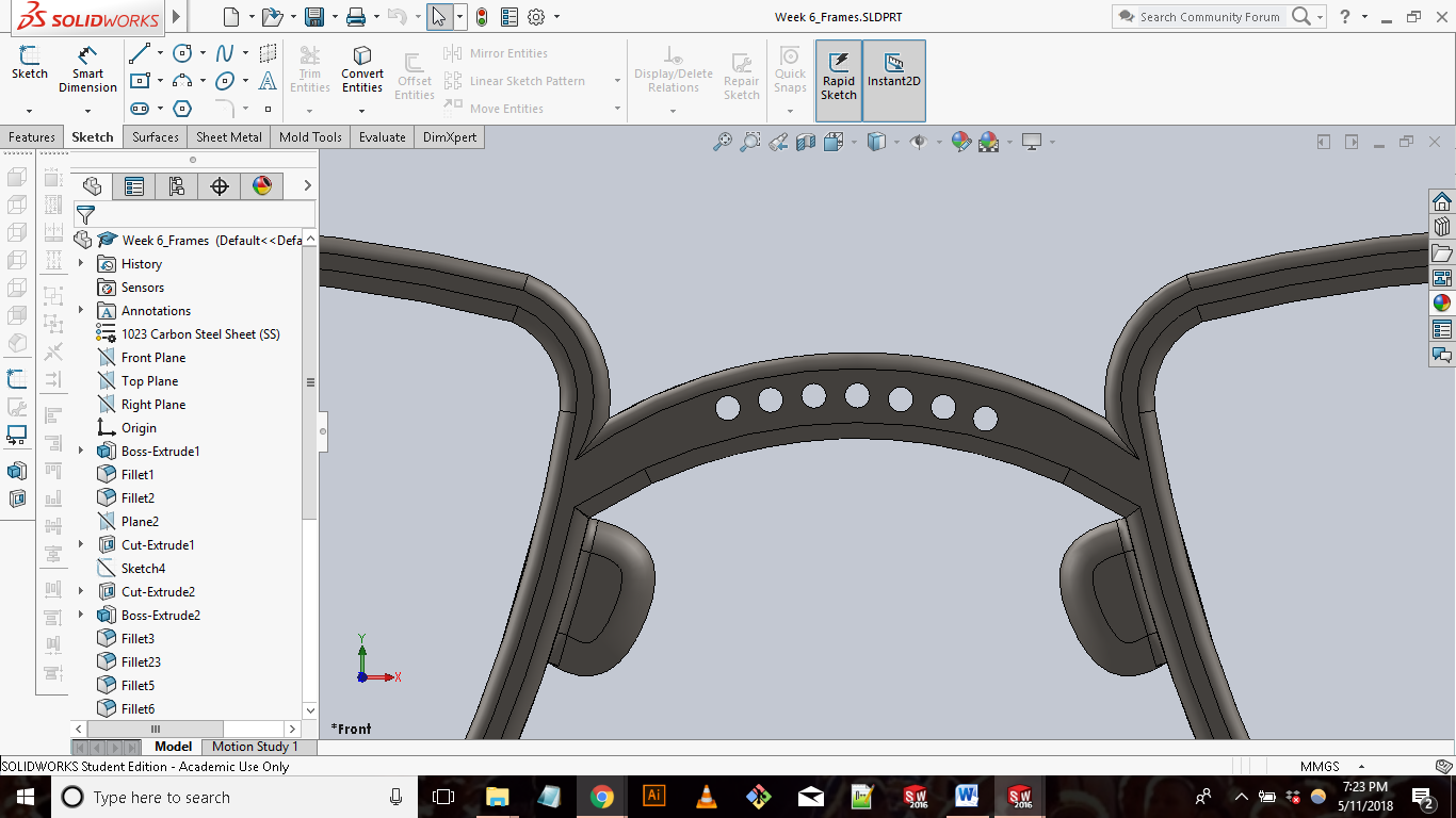
The second set of changes I made was to add a few extra features to the frame. Originally when designing the frames I only focused on the lens portion of the design, neglecting all the other features that come with realistic eyewear. This time around I added NOSE PADS and a CURVED BRIDGE to increase comfort and fit. Also I added fillets all around the design to improve the finish.
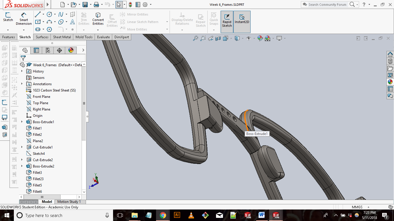
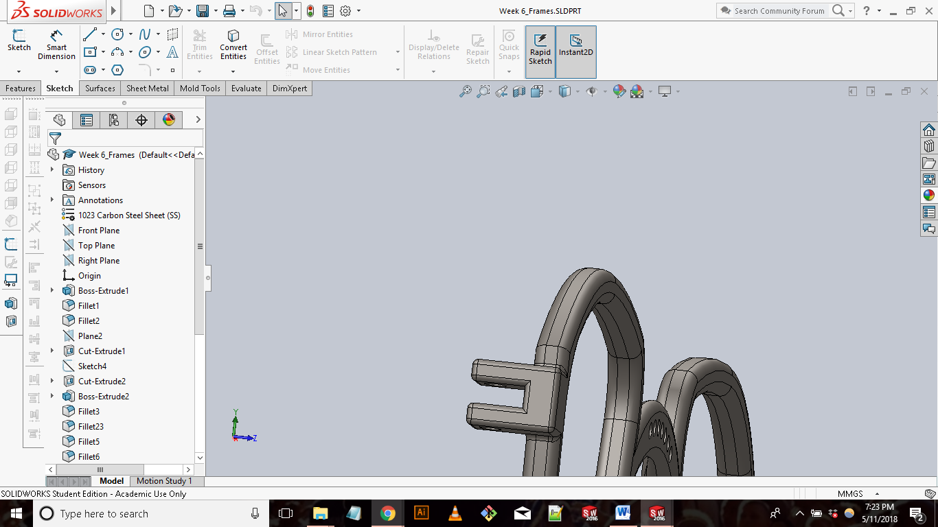
The third set of changes implemented was targeted at the hinges. Doing my own research and google kung-fu I found various 3D printed eyewear that utilized living hinges to create hinge-less glasses. I really liked this idea. I chose to explore this and created simple living hinges on the temples.
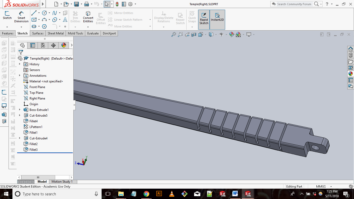
[NOTE: I also removed all the aesthetic designs that my older version had. They were poorly designed and were not functional. They actually compromised the integrity of the print.]
|Print|
For my second attempt at printing the glasses, I decided to use two different printers, the WoxD200 and FormLabs. Since both printers use different
printing methods and material I wanted to compare the results to see which gave me a better product. I used the native Preform and 3DWox’s native software
to convert my STL Files into gcode. For the 3DWox I used the standards ABS resin. The estimated print time was 2h 30mins. For the Formlab Fuse 1 I used to
different resins, Flex and Tough. Both prints on the Fuse 1 were estimated to take 12h 30mins.
I was able to record a wide variety of results from my prints. First the print made on the 3DWox was the worst out of the three prints. With the 3DWox Instead of printing the glasses as one solid print, I tried printing the glasses as three separate prints for assembly. This ended up being the wrong approach. ABS is pretty stiff which makes is brittle and does not allow the living hinges feature translate well. Also removing the pieces from the support tray proved to be almost impossible. The glasses made on the Fuse 1 with Flex resin also had bad results. The glass came out pretty well but due to the charactieristics of Flex the glasses easily snapped when handling, especially at the living hinges location. I got the best results from my print on the Fuse 1 with Tough resin. Tough as a resin is pretty durable, the glasses printed out really well. I was impressed by how well the living hinges worked. I was able to bend the temples almost flush to the frames without feeling like the temples would snap.
While 3D printers are great for complete customization, they are relatively pretty slow when it comes to producing objects. The four prints I made in total took around 30 hours to complete. That is pretty long for four small glass without out any great details.
3D SCANNING
For the 3D scanning portion of this week I decided to use the high end Creaform HandyScan 3d scanner. The Creaform scanner requires the use of "positioning dots" or small circular stickers to capture an object. Depending on the object you are trying to scan you can either place the positioning dots on directly on the object or in the background in relation to the object. For my item I decided to try and scan using the Creaform 3D laser scanner.
I placed the positioning dots on wooden speakers we had in the lab and proceeded to scanning. The scan didn’t come out that great. Im assuming it was due to me not being familiar with optimal positioning dots location and the size and shape of the speaker.
My take away is 3D scanning isn’t perfect. I can see there being a good amount of post fixing and patching after the initial scan. Even though, 3D scanning does provide a good base for someone who wants to capture an object in real life.
FILES:
3D Printed Glasses