WEEK 3
Computer-Controlled Cutting
Assignment:
Vinyl Cutting
- Identify and explain processess involved in using this machine
- Design and Create the final Project
Laser Cutting
- Demonstrate and describe parametric 2D modeling processess
- Identify and explain processes involved in using the laser cutter
- Develop, evaluate and construct the final prototype
- SolidWorks
- Rhino
- Adobe Illustrator
- Parametric Design
- Laser Cutting
- Vinyl Curtting
Software:
Skills/Concepts:
VINYL CUTTER
I am really excited about this week’s assignment. I have always been interested in creating and making stickers of my own. For the vinyl portion of this week’s assignment I wanted to design a sticker for my friends.
The first step in creating my sticker was designing the sticker. For the design process I used Adobe Illustrator as my main software. I found a picture that I like. The image I decided to choose was a picture of two young children hugging each other. I thought it would be dope to flip this image and add some of my own creativity to it. After finding an image I imported the picture into Illustrator and used the Image trace feature on the image. Image trace is a tool that allows you to edit artwork by creating vector lines of from the original file. Image trace is a great tool because it provides you with tracing presets that are really helpful. For this assignment I used the “black and white” art work preset.
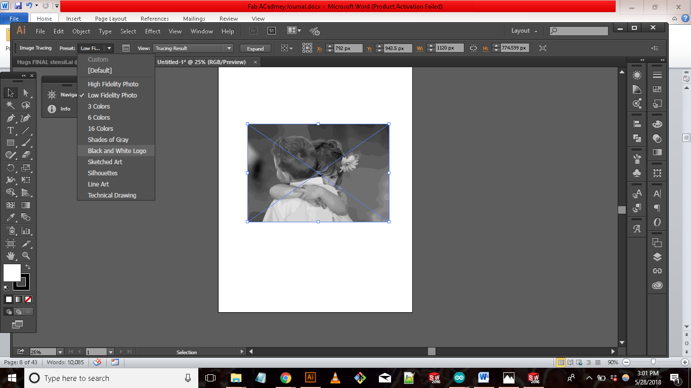
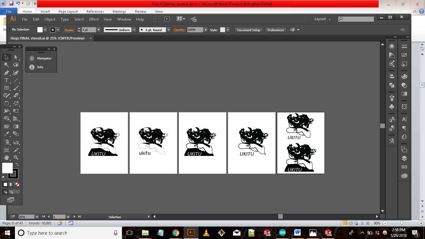
After image tracing the picture is pretty much ready for the vinyl cutter. All that was left was exporting the file as a png file. I did add “UKITU” to the image as my signature.


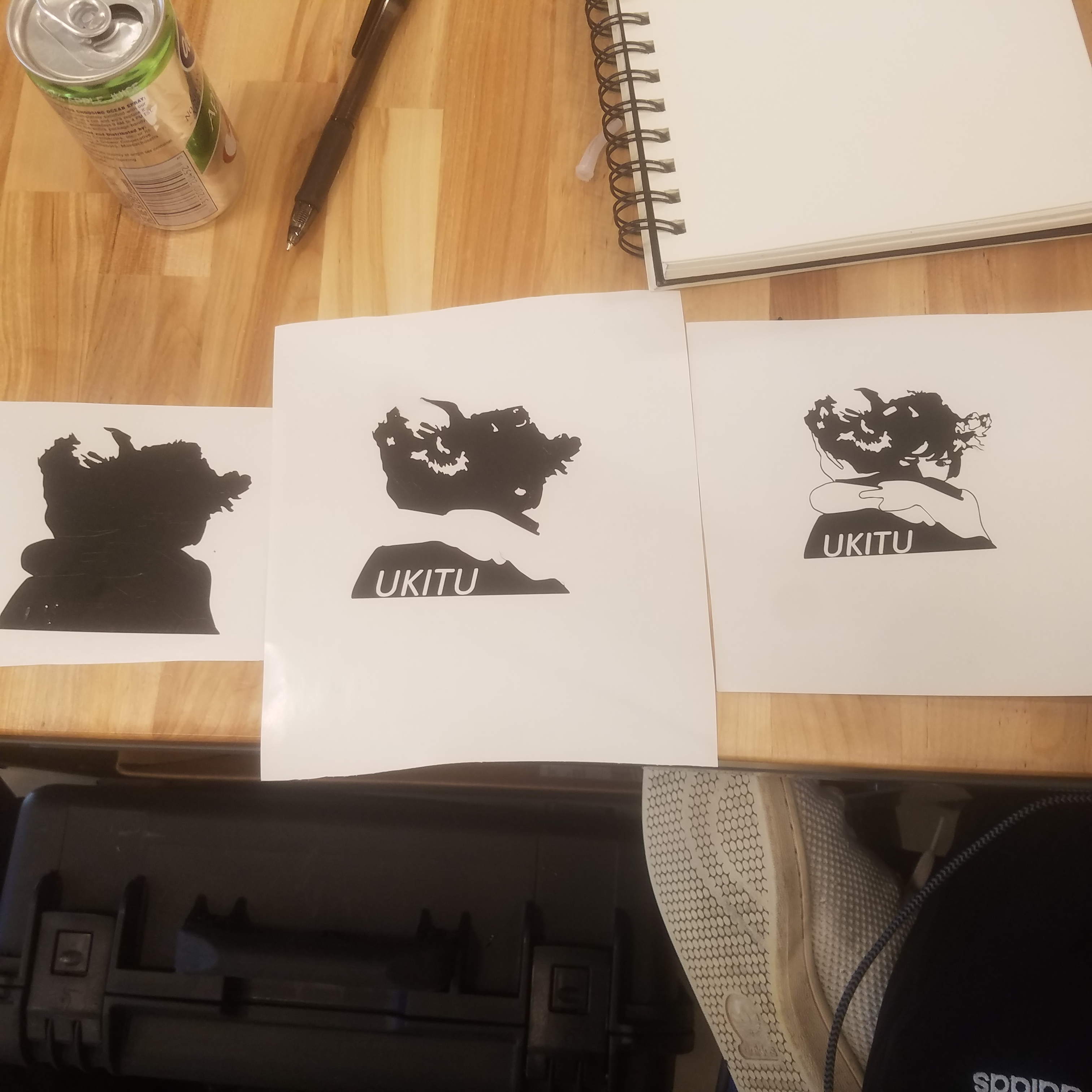
Once the file is exported, I then loaded up mods.cba.mit.edu (mods.cba.mit.edu link). I chose program > open server program > Roland > vinyl cutter. I then loaded black vinyl into the machine and sent the file to print. On the first go at creating my sticker the cut did not go all the way through, which made the sticker hard to peel. I then did a second print with and changed the force from 50g to 65g, which resulted in a better print but there were still problems with the sticker. During the second print I realized I needed to make some of the lines in my design thicker so the mods could pick them better. I also increase the force from 65g to 100g. Im happy with the results. The sticker came out well.


LASER CUTTING
"Folding Furniture"
The inspiration behind this portion of week 3’s assignment was Neil’s challenge to create 3d object from 2 dimension material. I have always been fascinated by furniture and thought this would be a good time to try my hand at creating some.
The first step I took was brainstorming design concepts. For my design I was inspired by “pop-up” cards. I found these two great books called “Folding Techniques for Designers: From Sheet to Form” and “Cut and Fold Techniques for Pop-up Designs”. I found both books to be very inspiration during my brainstorming process. From these books I was able to make a few mock designs using paper from a sticky pad.
After creating a few mock ups , I found a design that would work.
Now that I have a working design, the next step I took was transferring the design to a parametric software. Before using SolidWorks, I had to think about how I can use the laser cutter to mimic “folding and cutting” a piece of paper. My solution was to create panels that would be assembled in manner that can be folded and unfolded.
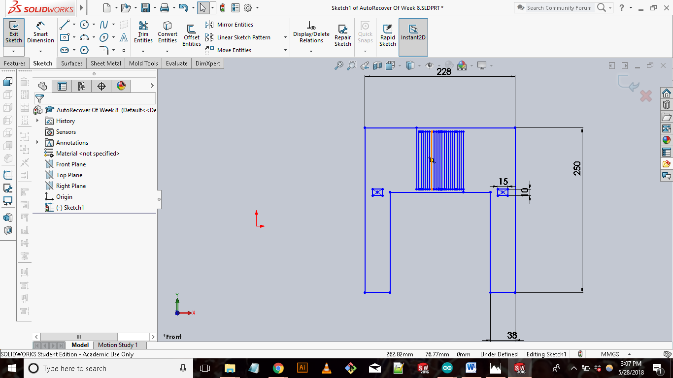
To begin my sketch I created an 228mm x 250mm rectangle. The reason for the box is that it acts as a design boundary. The laser cutter in our lab has a limited width and height, and in order to keep my design inside these limitations I made all my designs inside the box I sketched. The next step is to add the cut lines within the box. The first thing I did was creating a 152mmx152 square within the box and added lines to the square that mimicked the folding lines of my prototype.
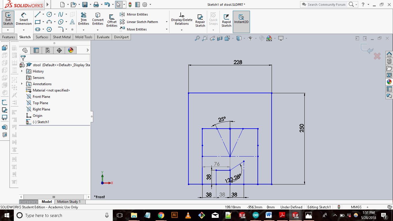
With the rest of the larger rectangle, I created the back rest of the chair. I add kerf cut lines in the middle of the back rest to allow it bend during its assembly.
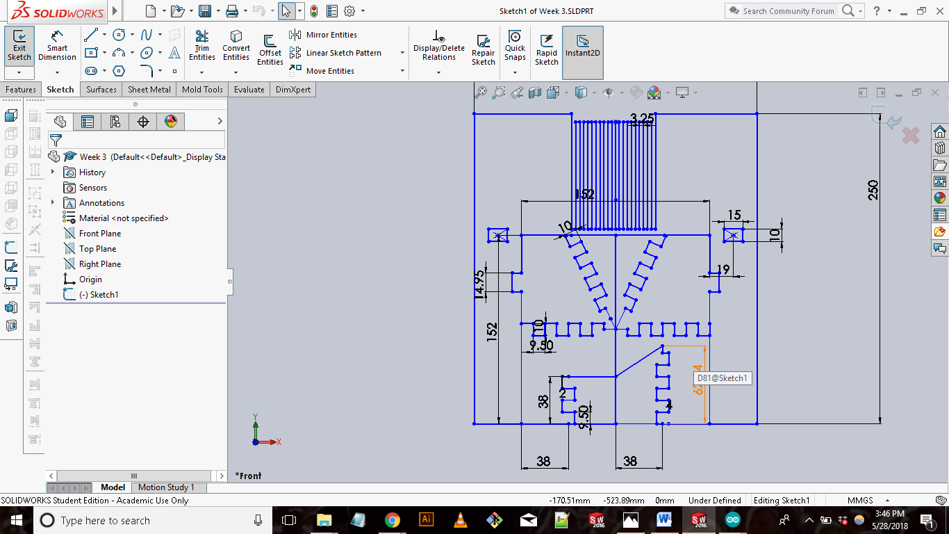
Once I was done with the design I exported the file as a dxf to work with the computer hooked up to the Laser cutter. In our lab the laser cutters is connected to a computer that has Rhino and Adobe Illustrator. The process of setting up a drawing is similar on both. For this assignment I used Rhino. After opening up Rhino, I imported my dxf file from earlier into a new drawing. I then go to file>print to put in the settings for the laser cutter. I was using an Epilog Mini Laser cutter and cardboard as my material. To vector cut cardboard the laser cutting settings are:
Speed: 40%
Power: 45%
Frequency: 500 Hz
I then selected print after getting the settings ready for my cut. Selecting print sends the cut file to the laser cutter which is then ready to go whenever. Before pressing go I loaded the laser cutter with a 18” x 12” piece of cardboard and turned on the exhaust and ventilation system. All that is left to do is press go. The cutting went well. I was satisfied with how the pieces came out. I then assembled the pieces together. I used bamboo sticks I had lying around my house as a rod to connect the panels together. The chair came out better than expected! In hindsight there are a few fixes I would add to the design but as a first time furniture maker, Im happy with the outcome.
FILES:
Laser Cut Chair (SolidWorks)
Week 3 Stencil (Adobe Illustrator)
Week 3 Stencil (PNG)