WEEK 2
Computer-Aided Design
Assignment:
- Model (draw, render, animate, simulate,....) a possible final project and post it on your class page with original 2D and 3D files
Software:
- SolidWorks
Skill(s):
- Drawing
- Product Design
- 3D Design
GETTING STARTED
I am excited for this week’s assignment. I would say at the moment my forte is 3D-Aided designing. Entering Fab Academy, I have a fair of amount of experience with a few designing tools, specifically Solidworks. I am interested in trying out the other software that Neil mentioned during this week’s lecture. My goal for this week is to try out Sketchup (https://www.sketchup.com/), Inkscape (https://inkscape.org/en/), Tinkercad (https://www.tinkercad.com/), and Fusion 360(https://www.autodesk.com/products/fusion-360/overview). I am really interested in Fusion 360 because majority of my classmates seem to be gravitating towards this one as their go to 3D design software for the program. I’ve decided to go with Solidworks because1. Even though I am familiar with Solidworks, I am no expert in the software. I would like to increase my skills and become a master of the software before moving to another one.
2. I don’t want learning new software to hinder my chance to learn more important principles and applications during Fab Academy.
3. Dassault Labs gave us a 6 month student license
I also tried looked into a 2D software, specifically Adobe Illustrator . Illustrator is a powerful vector based 2D software. I like Illustrator a lot. The user interface is easy to understand, the controls are fluid and the capabilities are endless. Im not sure how much I will use illustrator when it comes to Fab Academy but I can see myself using illustrator in the future for design work.
CONCEPT/DESIGN
One of the ideas for my final project was to create a “SMART” lamp. I imagined the lamp to have the ability to automatically change lighting color, mood lighting and alarm clock synchronization. At first I was extremely excited to about the idea but as I thought about my final project my excitement started turning towards my functional textile idea. Even though I decided to go a different direction for my final, I still wanted to create a unique type of lamp for my own pleasure. I simplified my original idea. What I came up with was a lamp that uses inductive charging to turn on and off. The lamp will consist of two parts and base, that holds the inductive transmitter and a top that holds the receiver. When the top is placed on the base energy will be transmitted to the top through the receiver and wala la the lamp is on!
Picture of Lamp Sketches
CAD
|BASE|
There were a few CAD programs mentions in this week’s lecture that spark my interest. Inkscape, Sketchup, TinkerCAD and Fusion360 all seem pretty interesting.
Fusion360 specifically since majority of my classmates decided to go with this as their main CAD program.
Ultimately I decided to go with SolidWorks as my main CAD program. I have a fair amount of experience with SolidWorks but if I am to be honest with myself,
Ive only use around 5% of the software’s capabilities. My goal for this week and Fab Academy is to increase my knowledge and mastery of Solidworks.
I believe when I do improve my knowledge of SolidWorks I can then transfer my skills to other Softwares like Fusions360 since they share some similarities in how they operate.
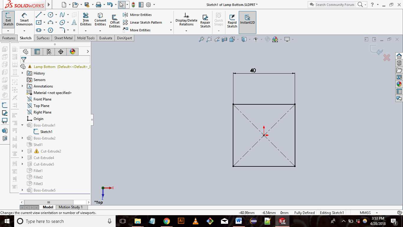
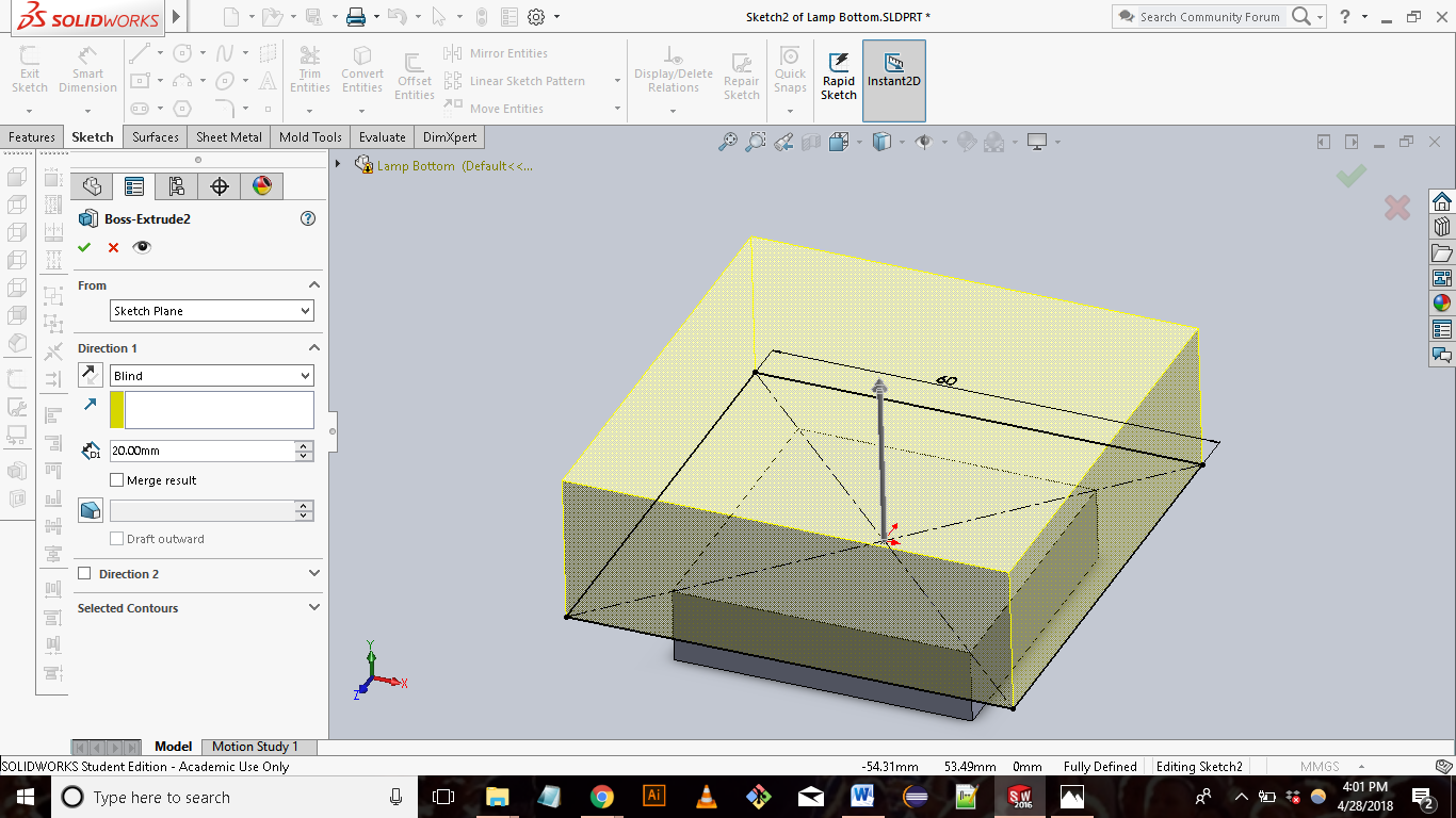
First, I created the 3D model for the base piece of the lamp. I started with a 2D sketch of a 40mmx40mm square then extruded it
10mm to create the foot of the base. On top of the extruded piece I created another 2D sketch of a 60mm x 60mm square and extruded it 20mm.
(Quick Note: Before taking Fab Academy when using Solidworks I use to dimension my designs using inches as this was the unit of
measurement I was most use to. After some discussion in class I switched to using Milimeters as my unit of measure. Millimeters is more
accurate and more widely used which makes designing parts and communicating with other regions, manufacturers etc much smoother.)
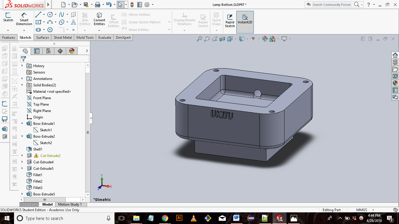
Next, I created a compartment for the electronics using the “shell” tool to create a pocket in the 60mm x 60mm square I just created.
I then used the “cut extrude” tool to create pin holes for a lid and a hole to put slide the wires through. To finish the part added filets
to round the corners and “Ukitu” on the front face.
|TOP|
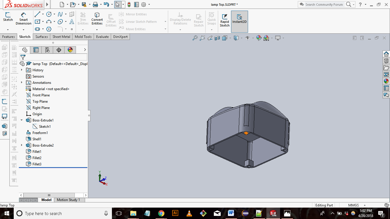
The steps to create the lamp top were similar to the process to create the bottom. I started with a 2d sketch of a 60mm x 60mm square and extruded it 30mm. Next, I used the “freeform” tool ( I nevered used this tool before but I wanted to try something new) to create organic contours on the top face of the extruded piece. I then used the shell tool to hollow out the square, added fillets to the corners and cut out pin holes for the lid.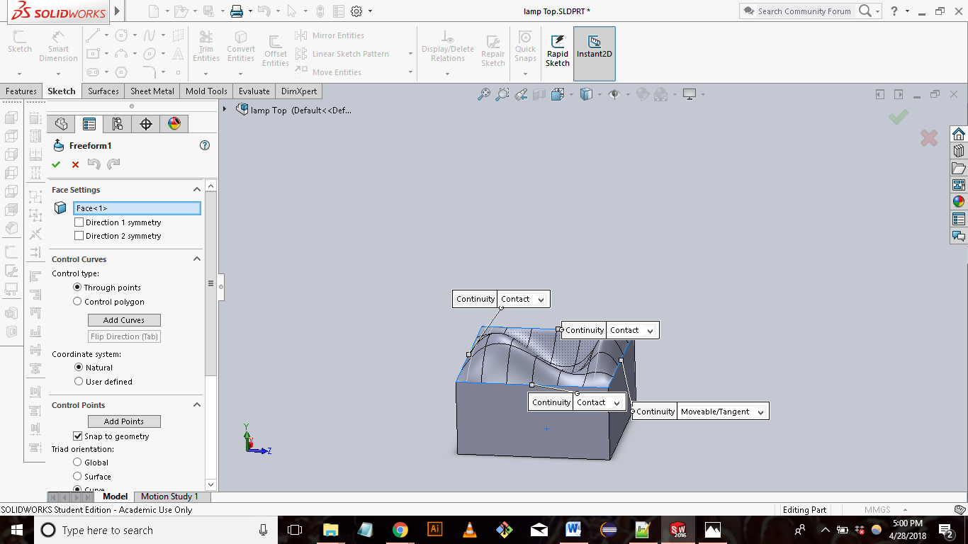
|LIDS|
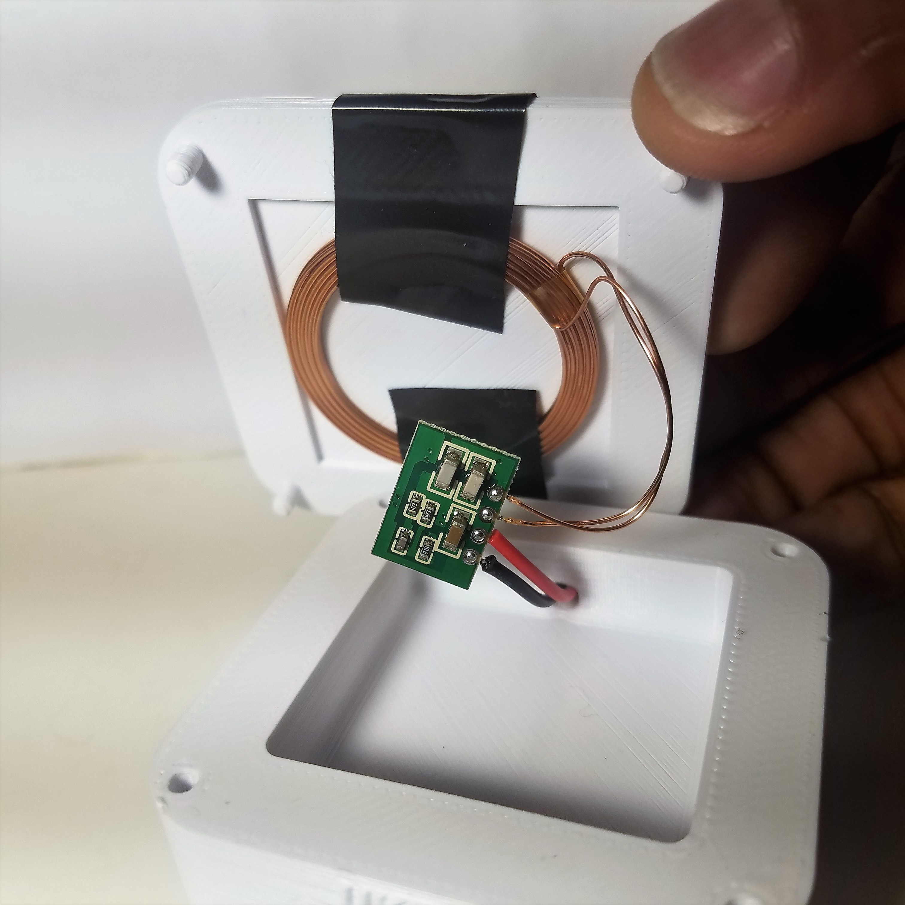
The lids were the simplest part of the lamp. I simply sketched a 2d 60mm x 60mm square, extruded 3mm, and added pins to all four corners. I used the extrude cut tool to cut a small pocket at the center of the lid where I would tape the electronics to. I wanted the lids to be very thin so the energy exchange between the inductive transmitter and receiver could be efficient.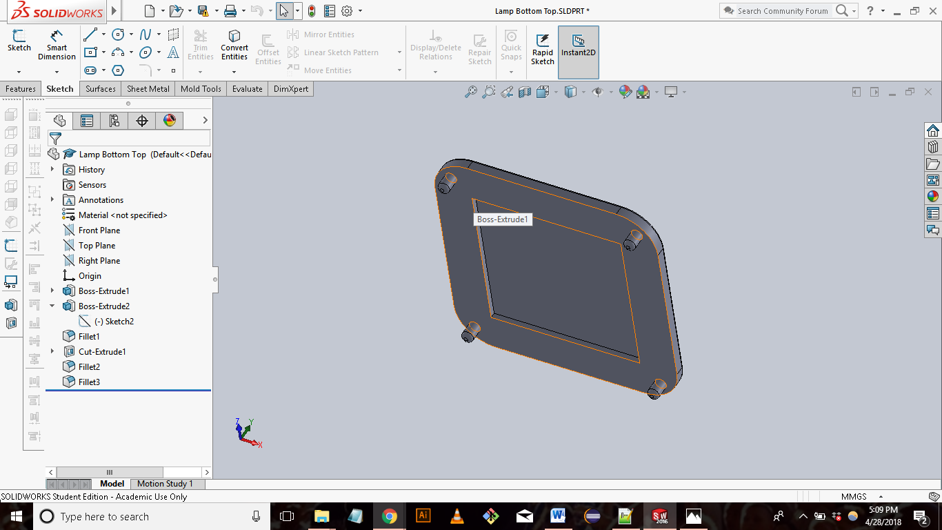
|Assembly|
The next step was to assemble the parts together to make the complete lamp. This is was pretty straight forwards. After creating a new assembly file, I used the “match” tool to align the parts and place them on top of each other.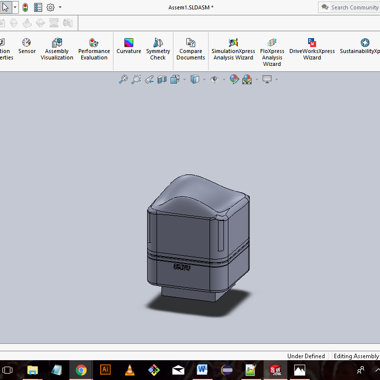
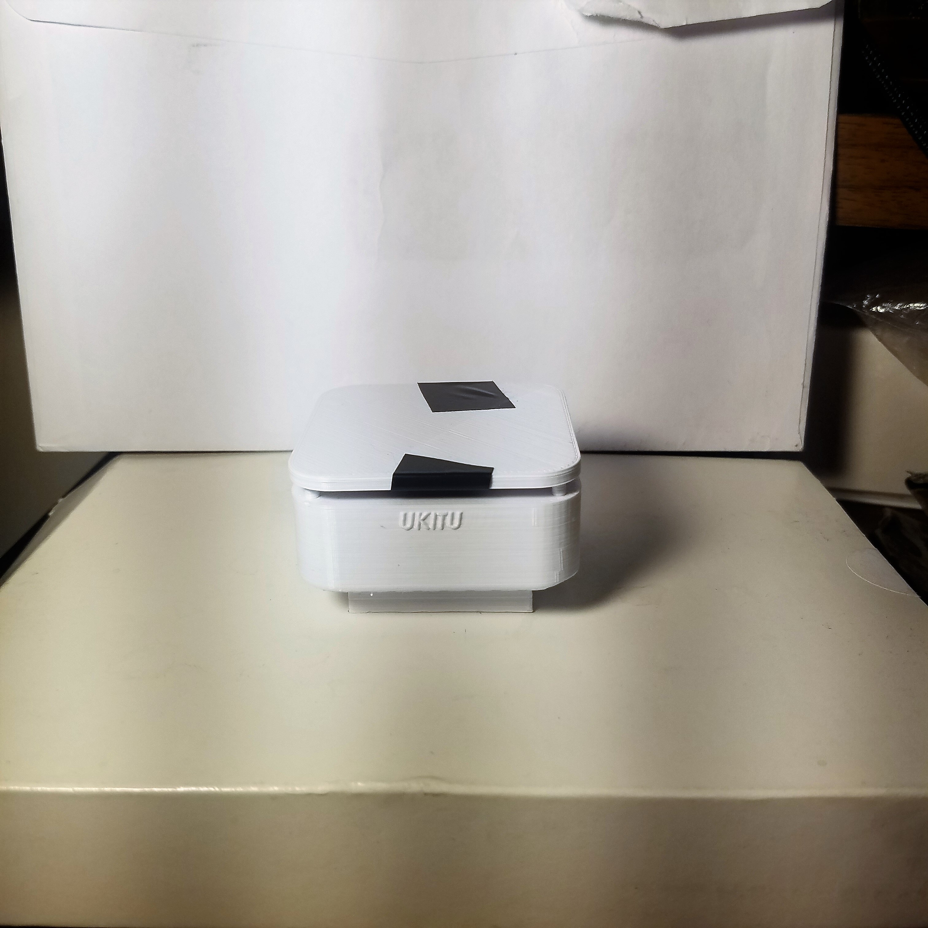
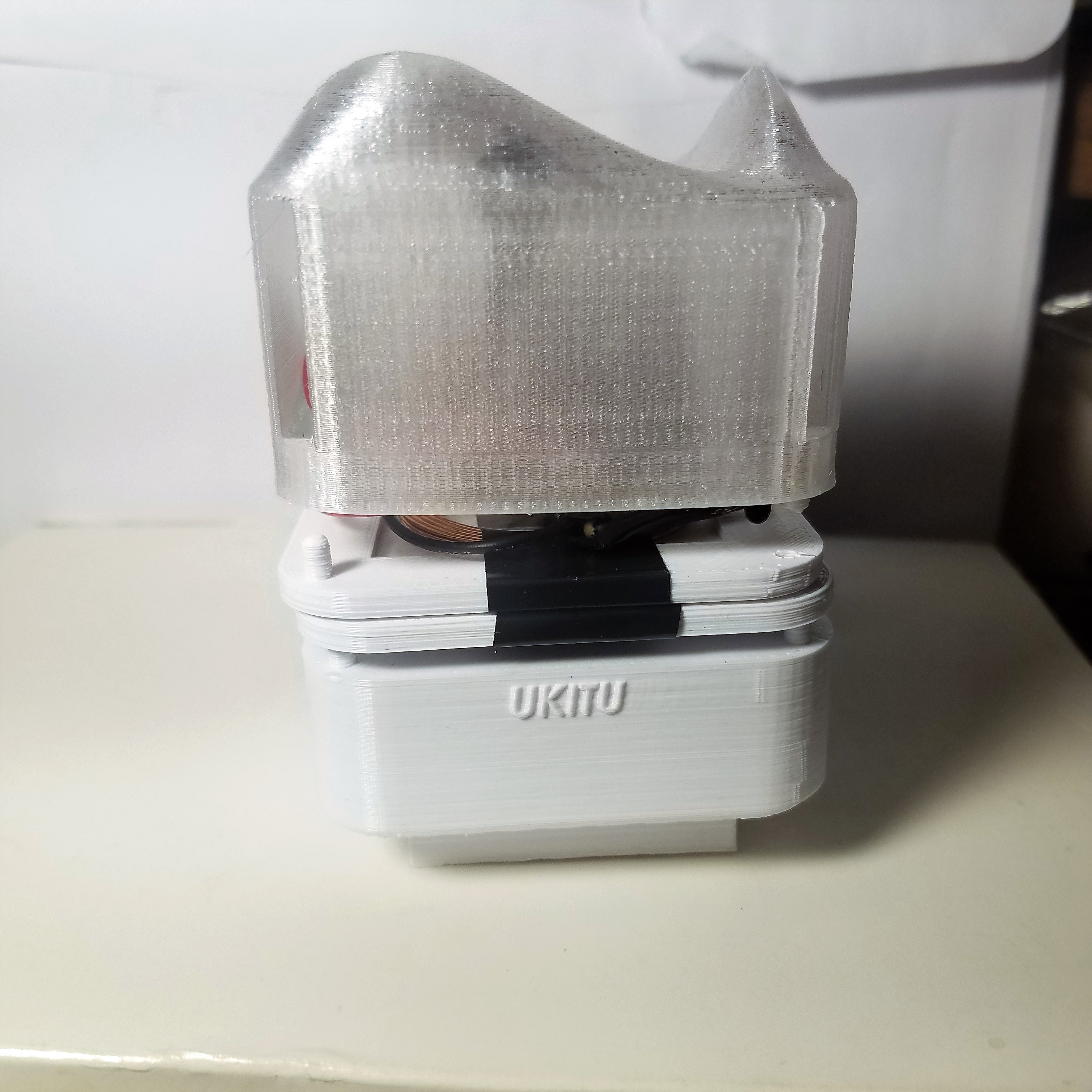
Update: I ended up printing this prototype. For the base I used basic ABS and for the top I used the clearest resin we had in the shop. There are a few changes that can be made to the design but overall the lamp works as a proof of conept.
