Exercise 8. Embedded Programming
Assignment: Embedded Programming
- Read a microcontroller data sheet
- Program your board to do something, with as many different programing environments as possible
- Optionally, experiment with other architectures
- Compare the performance and development workflows for other architectures (group project)
Learning Outcomes
- Identify relevant information in a microcontroller data sheet
- Implement programming protocols
Evidence
Process
I jumped ahead in Exercise 6 because I was eager to program my board. New to programming, I decided to use the Arduino IDE. The tutorial for this week was immensely helpful.
In testing my board I realized that one of my connections wasn't great and in trying to fix it, damaged one of the traces. As a solution I used a piece of wire to reconnect the traces. It's not pretty but it is functional!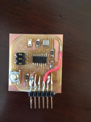
Reading a Datasheet
I downloaded the datasheet for the Attiny 44 microcontroller and started reading. I don't have the knowledge to make sense of much of the datasheet but did find some parts helpful as I tried to understand my board. Sparkfun's tutorial on how to read a datasheet helped break down specific parts that are universal to all datasheets.
Looking at the pin configuration, I was able to understand why components connect to specific pins: the crystal to pins 2 and 3 for example.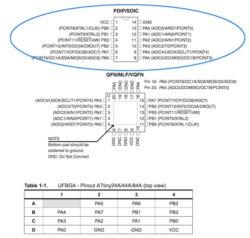
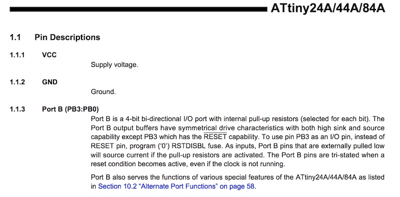
Next in the datasheet is a description of what each pin does.
I suspect that as I continue designing and programming my own boards, I'll make greater use of datasheets.
Programming the Board
I used the steps laid out in Anna Kaziunas' tutorial and in the tutorial from High-Low Tech as guidelines. An additional helpful resource was this Nuts and Volts video.
I already had the Arduino software on my computer so the next step was to add the drivers for FTDI so my computer can communicate with my board.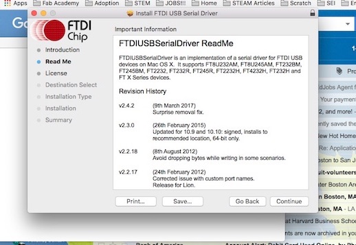
In order for the Arduino IDE to communicate with my board I added the board manager for ATtiny.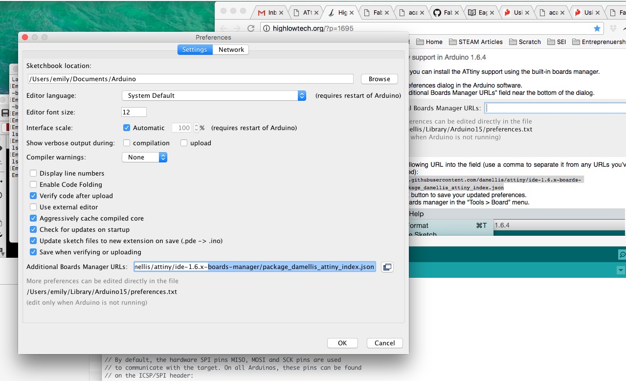
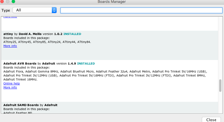
From this point onward ATtiny appeared in my Board menu.
Arduino
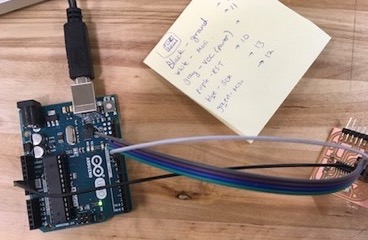
I connected my Arduino to the computer and to my board using this pinout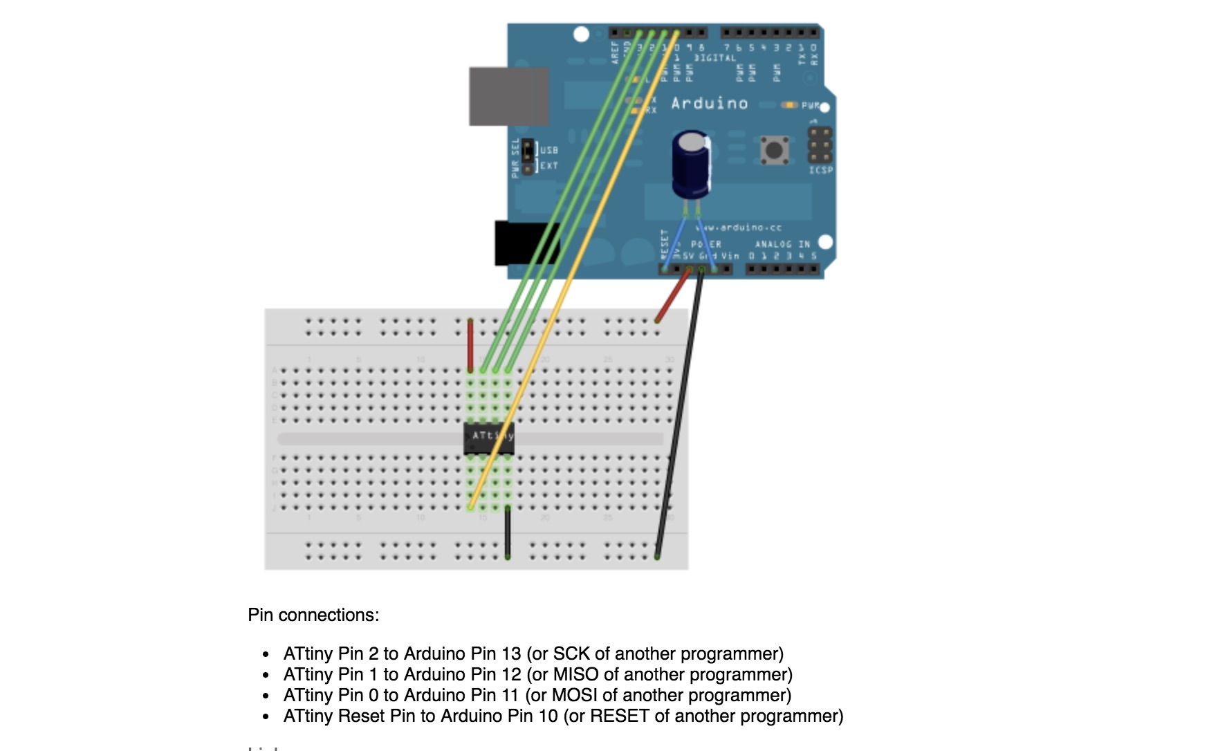
I set my board as the ATtiny44 (external 20MHz clock) in the menu and attempted to burn the bootloader.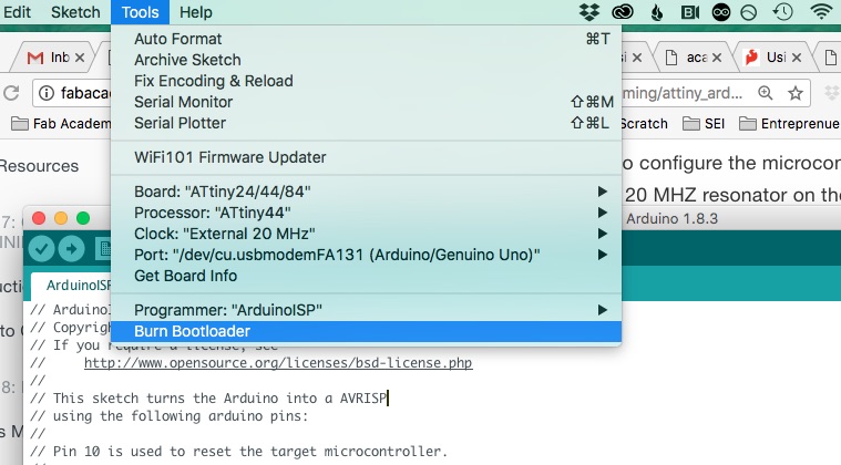
As you'll see below though, this was a fated endeavor as I hadn't supplied power to my board.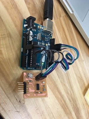
Even with both boards receiving separate power, I was unable to burn the bootloader.
FabISP
Next I tried to program my Hello-World board with my FabISP. I referred to the Eagle board files to make sure I connected my ribbon cable properly and provided power to both boards.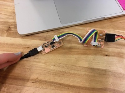 With this setup I was able to burn my bootloader.
Sending code
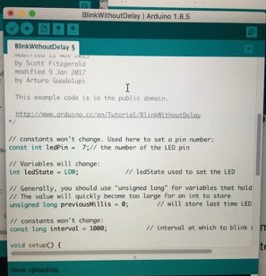
After finally successfully burning the bootloader it was time to program! First I tried the Blink code built into Arduino IDE's examples.
I also tried Blink Without Delay and Button. It was very satisfying to see the LED light up and then to control it with the push button!
Next I moved onto the code from the tutorial.
/*LED Off Until Button PressedBlinks a light emitting diode(LED) connected to digitalpin 7, when pressing a pushbutton attached to pin 3.The circuit:* LED attached from pin 7 to ground* pushbutton attached to pin 3 from +5V* 10K resistor attached to pin 3 to +5V* 10K resistor pulls pin 3 and the button to HIGH by defaultcreated 2005by DojoDavemodified 30 Aug 2011by Tom Igoemodified for Hello Button + LED Board - 19 Mar 2012by Anna Kaziunas France*/// constants won't change.// They're used here to set pin numbers:const int buttonPin = 3; // the number of the pushbutton pinconst int ledPin = 7; // the number of the LED pin// initialize variables:int buttonState = 0; // variable for reading the pushbutton statusvoid setup() {// initialize the LED pin as an output:pinMode(ledPin, OUTPUT);// initialize the pushbutton pin as an input:pinMode(buttonPin, INPUT);}void loop(){// read the state of the pin the pushbutton is connected to:buttonState = digitalRead(buttonPin);// is the push button pressed?// if not pressed - the button state is HIGH// the pull up resistor the button / pin 3 makes the button state HIGH by default.if (buttonState == HIGH) {// turn LED off (LED is off by default)digitalWrite(ledPin, LOW);}//otherwise.....// button is pressedelse {// turn LED on:digitalWrite(ledPin, HIGH);}}
Writing code
The Arduino website has a number of tutorials to break down the basics about the platform, how a microcontroller and its pins function and programming in the IDE.
After a comment section, the first part of a sketch is the setup which preps the board for its task and the second part is the loop, where the bulk of the code lives.
I experimented by changing around the above code. I used the aforementioned codes to remix the Button code by adding longer loops, mixing up the delays, and changing the functionality of the button.
// constants won't change. They're used here to set pin numbers:const int buttonPin = 3; // the number of the pushbutton pinconst int ledPin = 7; // the number of the LED pin// variables will change:int buttonState = 0; // variable for reading the pushbutton statusvoid setup() {// initialize the LED pin as an output:pinMode(ledPin, OUTPUT);// initialize the pushbutton pin as an input:pinMode(buttonPin, INPUT);}void loop() {// read the state of the pushbutton value:buttonState = digitalRead(buttonPin);// check if the pushbutton is pressed. If it is, the buttonState is HIGH:if (buttonState == HIGH) {// turn LED on:digitalWrite(ledPin, HIGH);delay(500);digitalWrite(ledPin, LOW);delay(500);digitalWrite(ledPin, HIGH);delay(1000);digitalWrite(ledPin, LOW);delay(1000);digitalWrite(ledPin, HIGH);delay(250);digitalWrite(ledPin, LOW);delay(250);digitalWrite(ledPin, HIGH);delay(250);digitalWrite(ledPin, LOW);}else {(buttonState == LOW);// turn LED off:digitalWrite(ledPin, LOW);}}
Next steps
I can make small changes to code but don't feel confident that I could write my own scripts yet. Moving forward I would like to gain a better sense of C-based coding. I'm (slowly) working my way through a separate course in C and, in the spirit of spiral development, believe that the more that I remix other people's code to suit my needs I will gain a greater understanding.
I'd like to understand more of the microcontroller datasheet.
- How can I program a board to control a whole matrix of LEDs for my final project- storytime lantern or crankie theater?
- How does a makefile relate to the C/C++ code used in the Arduino IDE?
Architectures
Fab Academy focuses chiefly on use of microcontrollers like the Atttiny 44 used here. Microcontrollers are built with Harvard computer architecture that has two separate storage and signal areas. One of these areas is for commands and the other is for data. Mark I, the first programmable computer in the US, and other early computer systems also utilize this architecture. Most computers today utilize the more complex von Neumann architecture, composed of a central processor with a control unit and arithmatic/logic unit, memory, mass storage, input and output. In von Neumann architecture both commands and data are stored in one memory module. Microcontrollers are reduced instruction set computers (RISC); they perform a smaller set of instructions than a complex instruction set computer (CISC) does, but this enables them to perform at a higher speed. Microcontrollers abound in our everyday lives- they control everything from different systems in our car, to our smart phone, the LCD displays on our appliances, and more. Microcontrollers and their programs are embedded within other devices, usually run one program, are generally cheaper and usually require less power than larger and more complex computing devices. An Arduino Board utilizes a microcontroller. Even after reading up on the differences between microcontrollers and microprocessors, the below diagram found here was helpful in codifying my unnderstanding.

Although you can find them in cars and modern household appliances, they are most widely associated with your standard laptop or desktop computers. A Raspberry Pi, esentially a mini computer, also contains a microprocessor. Field-Programmable Gate Array (FPGA) and Complex Programmaable Logic Device (CPLD) are two other types of logic chips. Both of these are more flexible than microcontrollers and microprocessors becasue they have more programming capability. However, with their complexitiy comes increased cost, set-up time, and decreased speed.
Resources: Technopedia How Stuff Works Difference Between.net