Exercise 11. Output Devices
Assignment: Output Devices
- Add an output device to a microcontroller board you've designed and program it to do something
Learning Outcomes
- Demonstrate workflows used in circuit board design and fabrication
- Implement and interpret programming protocols
Evidence
Process
I wanted to create a LCD display to show data from the Hall Effect sensor. Since this is similar to a number of hamster wheel projects out there made with Arduino Uno, I decided an Arduino-like board would make sense to complete the exercise.
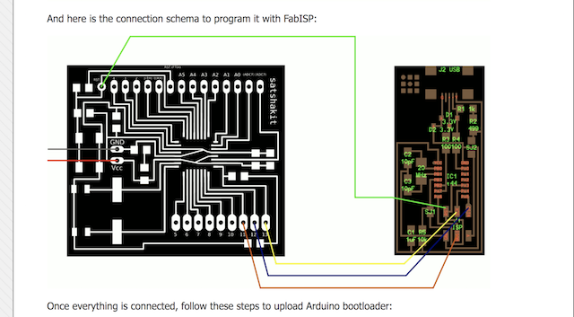
With recommendation, I decided to use Daniele Ingrassia's Satshakit as a base for designing my input/output board.
This more than any other exercise was a set-back week because
- I had difficulty creating a board layout that didn't have any airwires, and allowed for wide enough traces to mill
- I had difficulty milling my board- small close traces, a large board size (about 8cm^2 to accommodate LCD display), and an uneven toolbed all contributed
- Exercises 12 & 13 were dependent on me having a working board
BUT the sense of achievement and relief from a working board were also unmatched!
😄😄😄
Breadboarding
Luciano suggested I start with breadboarding to understand how components are linked and what I would need to add to a satshakit board to suit my needs. My go-to guru for this project was Andriy Baranov, a young Ukranian whose Fidget Spinner RPM documentation was the starting point for my project.
Connections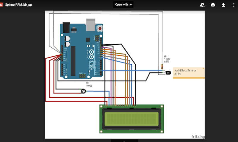
Breadboarding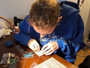
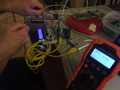
Potentiometer for adjusting brightness of LCD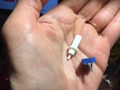
Checking voltage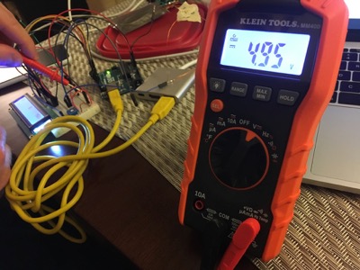
Working Input/Output
Designing board
Schematic
I already knew where to find the hall effect component in Eagle from the previous exercise.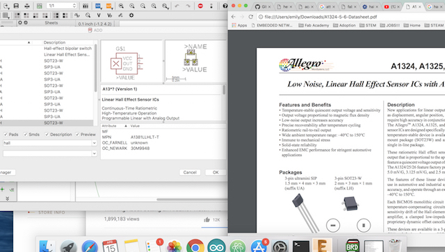
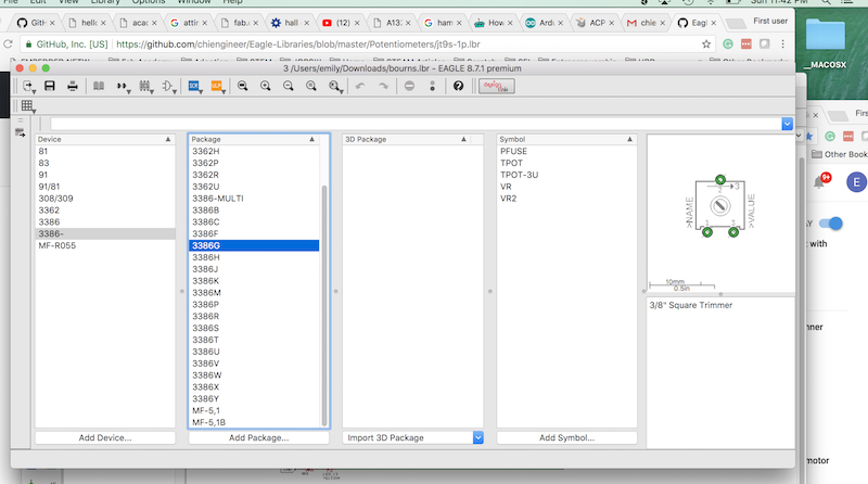
The LCD display I used isn't part of the standard Fab Lab inventory. I was able to find the Eagle library for it and the datasheet.
I had difficulty making sense of everything on the datasheet, but found this
tutorial
that helped break it down. From both documents I gathered what each of the pins were for, which was helpful in connecting them to my microcontroller.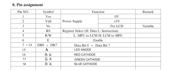
I'd mistakenly started with the micro Satshakit Eagle files.
Below: double-checking microcontrollers on standard build and micro build to ensure I have correct microcontroller and pinouts.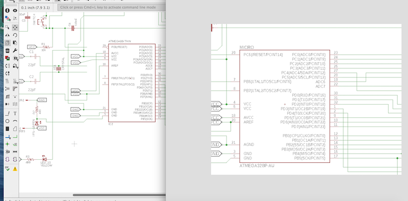
Adding the correct LCD package. I found the library for it here.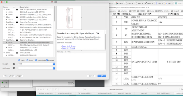
Adding the correct potentiometer package
Board Layout
While previously I'd enjoyed figuring out the best way to layout and connect various components on my boards, after a few days of this without being able to move on, it grew tiresome.
I did a few different iterations to make my board smaller.
In hindsight it would have been significantly easier to connect the LCD display with wires rather than build it into the board design itself or use different boards as shown here.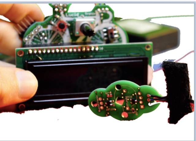
I ended up adding 3 0Ohm resistors in places where I just couldn't connect with traces.
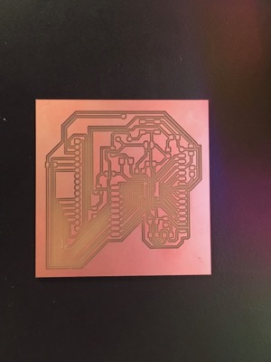
Finalized board layout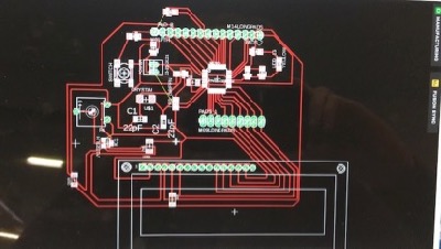
Creating Images
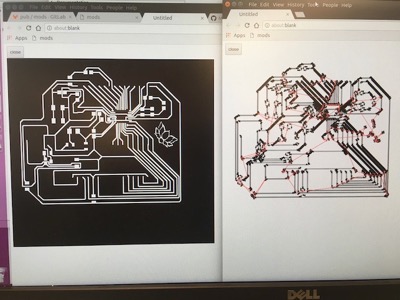
To make my traces I followed the same workflow as previously by exporting only the top layers to Gimp.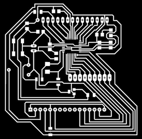
From Gimp I centered, added pixels around the edge, added a border, and flattened. I created a file for traces, and one for the interior.
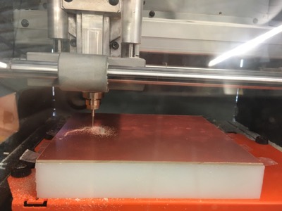
Milling Board
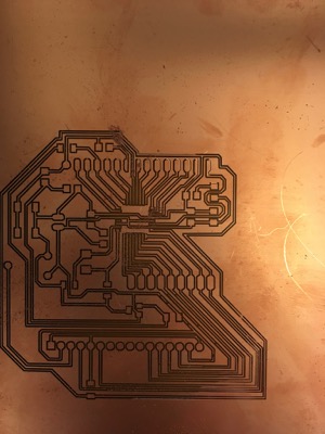
All in all I milled THIRTEEN modified satshakit boards. Three milled successfully. One of these three was missing a ground trace. One I severely damaged in the process of resoldering.
The third is a bit of a Frankenstein board but it works.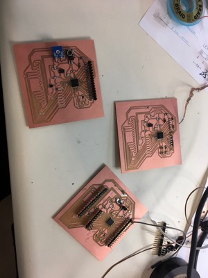
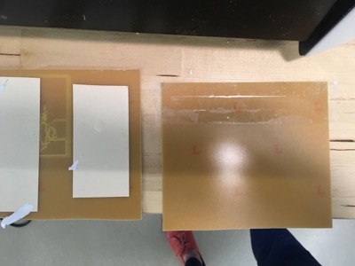
My board is too big for the small PCB boards we have in stock and the big pieces were too big for our bed, so I ended up cutting them.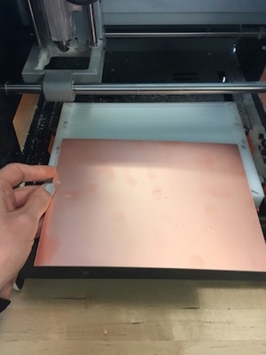
I loaded my first file, set my coordinates, calculated, and sent the file to the Roland.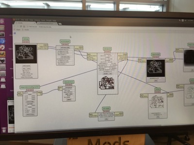
The finished product is not useable.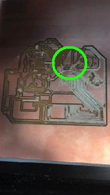
In between all the traces on the right side there is significant build-up of material. Possibly a sign of an uneven bed. Additionally, not all of the traces to the microcontroller are milled out (within the green circle). Had I looked more closely at the milling file created in a new window when I 'calculated' on the Mods software, I would have caught this.
In this run you can see that most, but not all, of the traces to the microcontroller will be milled out.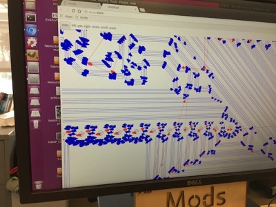
I did a lot of careful examination to see if traces would be milled out, particularly the ones near the microcontroller since they are so close together.
Changing Design
I adjusted the clearance in and changed the angle of some traces in Eagle in attempts to solve my milling problem.
Additionally, I resized some of the pads in Gimp to make more room for a trace that needed to go between them.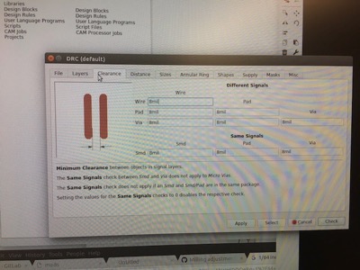
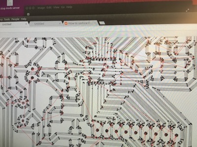
This fail is particularly interesting, and although some parts might be attributed to a broken bit, I'm not sure what is happening in the upper right where there's a visable shift in trace connections.
Additionally, I'd accidentaly "filled in" the outside ground wire in Gimp so even if this had milled properly, it wouldn't have worked.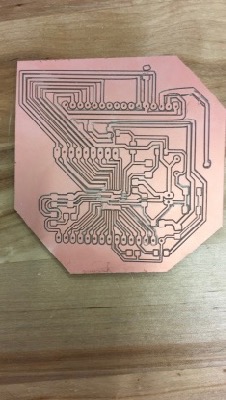
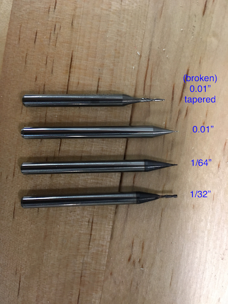
Changing Bits
At one point it was suggested to me to try a smaller bit. We did have some 0.01" bits in-house so I tried with one of these...and subsequently ordered more when I realized without understanding how to mill with them,
they break very easily. I broke two. Later on in my process, when reading more on the making of Satshakit boards,
I found that Daniele recommended using a 0.01" bit to mill.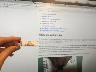
Attempting to use a smaller drill bit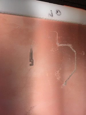
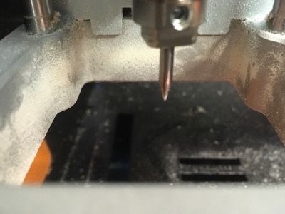
When using a smaller bit, depth of cut, feed, and speed, all need to be adjusted.
Notice in this particular run I set the speed to 1mm/s.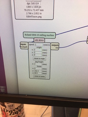
Jean-Michel lent me a tapered ball-nose tip, also 0.01" which milled about 1/3 of a board fine at a slow speed and then also broke.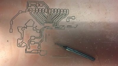
I also tried changing the bit-size in Mods. Using a 1/64" bit entered as a 0.01" bit did produce better milling while resulting in fewer broken bits.
Changing Machines
I switched to the older Roland Modela at CIC since I was having so much trouble. Although this machine doesn't have all the bells and whistles that the SRM-20 does, I found it to be a much more dependable machine. The Roland we often have to power off and restart or restart Mods.
On one of the jobs using the Modela, some traces were etched on top of the material rather than milled out. I tried to send an image file with only the parts that needed to be milled a second time but wasn't careful enough in editing the file.
Clearing image for a second run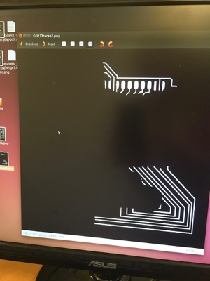
Changing Bed
Checking bed level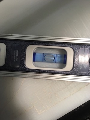
Eventually new material came in to replace our sacrificial layer. I still think that something on the machine itself needs some micro-adjustments though because there were differences in milling on the PCB with the replaced, level material.
Changing Offsets
I had the best luck milling the Satshakit when I reduced the number of trace offsets from 4 to 2.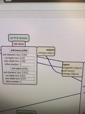
Changing Tape
The sturdier double-sided tape may be lifting our sacrificial material from the machine bed. I tried the thinner tape on two jobs.
Given the size of the board, even when affixed quite strongly to the sacrificial material, this tape did not seem to be strong enough.
Success
Twelve of the thirteen boards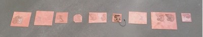
Lucky number 13! It was a very slow process to clean the clearances because I didn't want to damage the traces and the excess material was tightly packed in.
When I went to clean this board, I ripped off a pad while washing the board. Luckily,it wasn't one I was going to be using.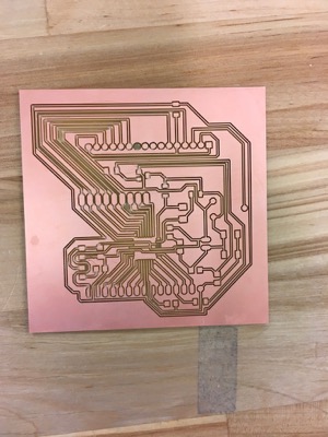
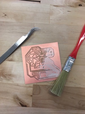
Stuffing board
It's very important to remember to check for your electronic components before deciding on and milling a board. There are a few components on the Satshakit that are not in the Fab Lab inventory and I had difficulty sourcing them. The mail order was delayed so parts were brought in from another lab.
Empty container of 22pF capacitors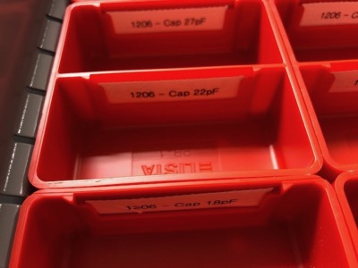
My components crossed off as I added them to the board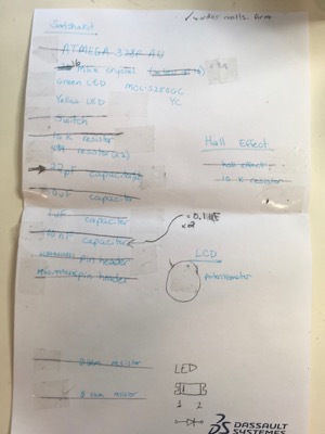
I soldered two complete boards.
I ripped up the pads for my potentiometer.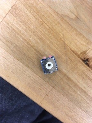
Given the challenges of milling, super glue seemed like a good fix.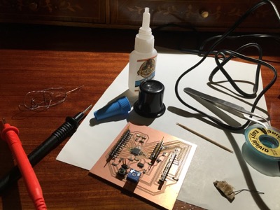
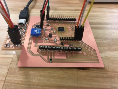
Stuffed board #1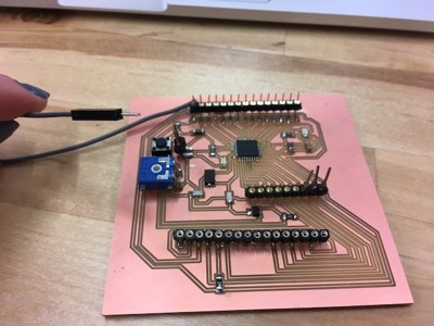
I didn't mill the holes in the original Satshakit design for fear of further failure. Instead I affixed headers onto the board. I'd later find out that the pins and through-holes on these headers were too small to make good connections. Notice the three larger headers soldered on mid-right.
I'd previously thought the Hall Effect component was tiny.
I ripped up two of the traces connecting my microcontroller- those are tiny This was no time to be milling again so I made some adjustments that are serviceable.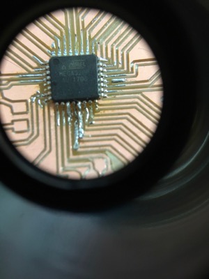
Had to come up with a workaround to connect the LCD for two-small headers.
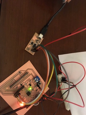
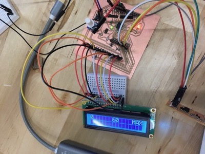
Unfortunately put the bend in the wrong direction, making it difficult to see the display (and access the sensor).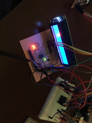
Programming board
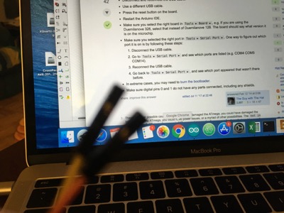
I programmed my board as an Arduino Uno using my FabISP by burning the bootloader.
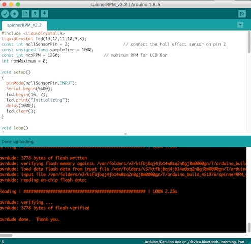
Sending Code
I went back to the datasheet to make sense of coding my LCD.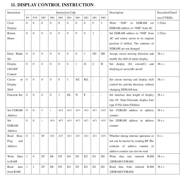
Incidentally, not much needed to be changed in the code from when I'd breadboarded with the Arduino because I'd designed the pinouts to be the same.
My computer dedided not want to cooperate. My board, any of my boards, could no longer be recognized by my computer.
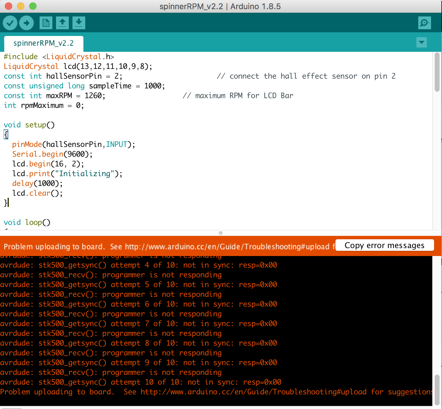
I switched to 'verbose output' in the Arduino IDE to see if I could get a better understanding of what was happening
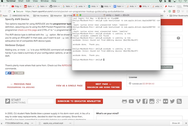
Checking FabISP connection through the terminal
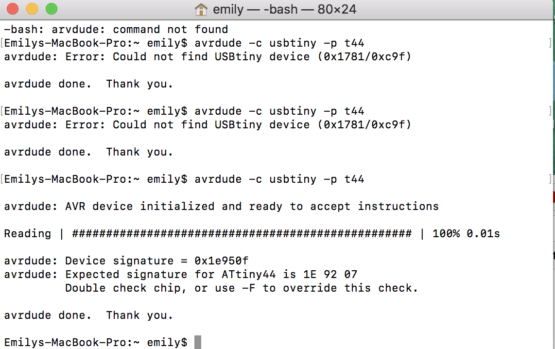
Hitting the forums I did find that this a common problem with newer Macs (I'd just needed to replace mine). On some I'm not able to see the FTDI but I can still program with it. However, no cord or board seemed to please my own.
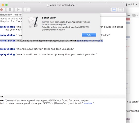
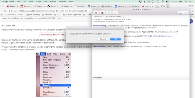
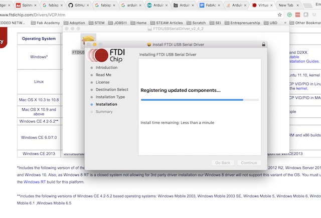
Uninstalling and reinstalling FTDI drivers
At one point I'd realized I mixed up USB cables and was using a 3V cord. Alas, switching to the 5V cord didn't solve the problem. Since neither I, nor my instructors had any further ideas, in order to move forward I'm programming my boards with a borrowed computer from the FabLab. I was finally able to program my board with my input/output code using my FabISP and another computer.

I've misplaced video of my board in action. Here is Ekeko, a pre-Columbian god of abundance and prosperity from Bolivia, as a placeholder.
Source Code:
Andriy Baranov's Fidget Spinner RPM test
LucidTronix Speedometer
Marc Selhorst's hamster wheel
John Mueller's hamster wheel pedometer
Next Steps
I am still working on code that will display both the speed and the distance. I did some basic calculations to translate rotational movement to distance and plugged this into LucidTronix code modified for my board pinout. This is still a work in progress as I've burned out my LCD and will need to switch to a breadboarded LCD in a different package. Additionally, I need to take a closer look at the datasheet to make sure I've substituted the right pins on my board.
Files
Adapted Satshakit with input and output: Eagle Schematic, Eagle Board
Monochrome Gimp file for milling: Traces, Interior
Code: Wheel RPM, Wheel Distance