Electronics Design
Assignment
redraw the echo hello-world board,
add (at least) a button and LED (with current-limiting resistor)
check the design rules, make it, and test it
extra credit: simulate its operation
extra credit: render it
And we're off
So this is the first assignment where I've really felt in over my head. I have no experience whatsoever with circuit design. I browsed the available software and again felt overwhelmed. I am doing the bulk fo my work from a Mac, and I'd rather not go through the trouble of running Windowns/wine/etc on my computer, so I'm going to stick with the programs available for my OS. I tried first downloading KiCad, but the download never seemed to begin and I could not figure out what the issue was. Next I moved onto Eagle. I downloaded the program no problem, got everything opened up, started exploring the environment, and got very overwhelmed. I think the part of the reason I had some initial difficulty getting used to the PCB design environment is that I was trying to treat it like a CAD environment and getting frustrated by my inability to simply navigate the program understand all the different tools.
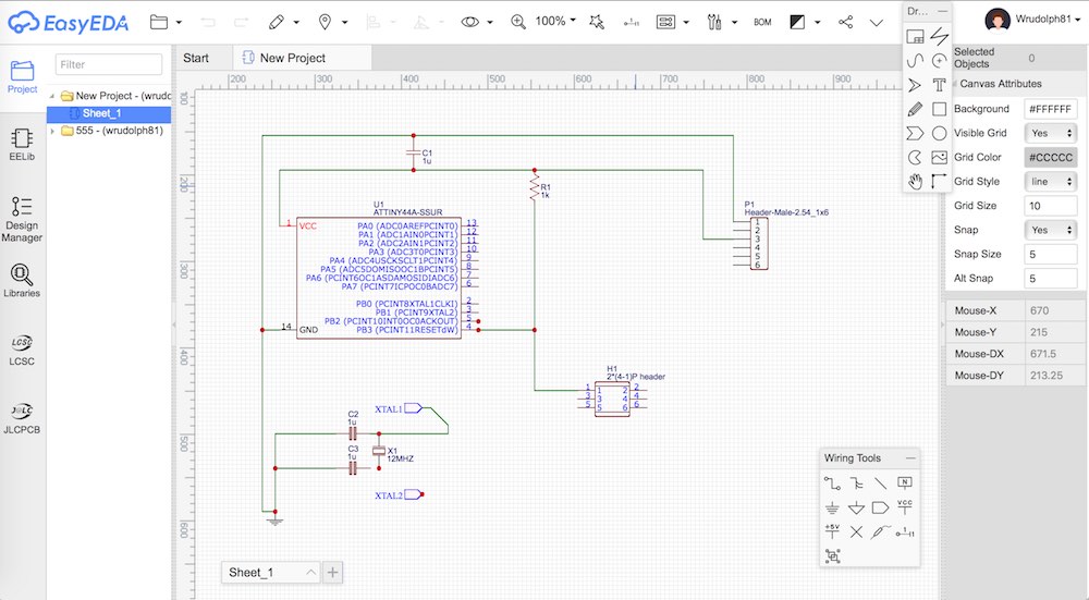
I figured I'd look at another program, maybe something simpler, to get a better footing in the PCB design world. After some searching, I found EasyEDA, a nice online platform for circuit and board design. The program was much easier to approach and let me begin getting used to the schematic layout tools. I started redrawing the EchoHelloWorld board from the image provided and soon became frustrated searching for parts and being uncertain about the pads that would be created. I knew I had better access to parts libraries in Eagle and thought I'd give it another shot after getting my feet wet with EasyEDA.
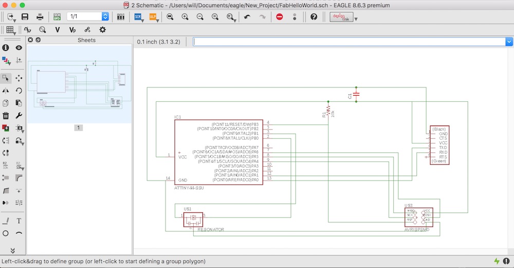
I watched a basic tutorial on Eagle and got to work.
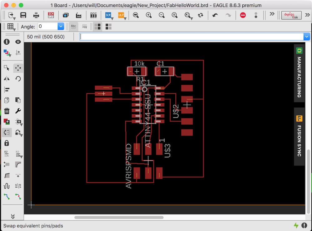
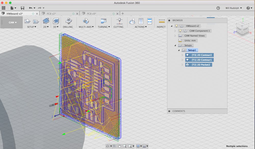
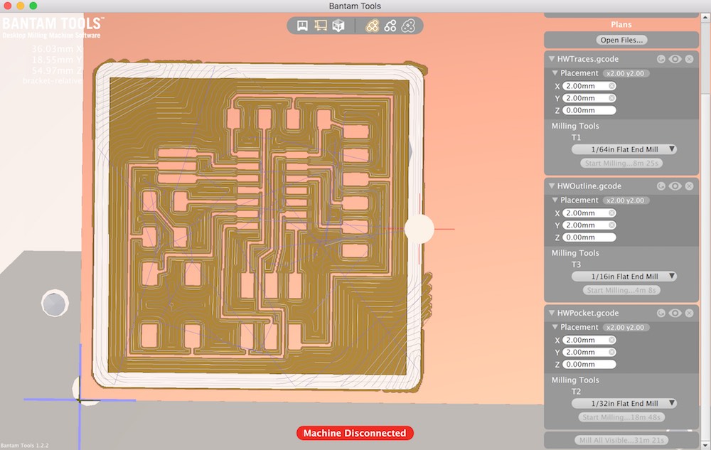
So I know you can generate the necessary g code files to mill the traces from Eagle, and we also have FabMods, but at this moment, I feel like having a little more control over the process, so I'm opting to take the png from Eagle, convert it to an svg through FabMods, then insert that svg into a Fusion file, extrude, check scaling, and create toolpaths. It's a little tedious, but I like the control it gives. Also this way if I want to create any sort of enclosure or add additional holes or milling procedures that are not standard to pcb manufacture, I already have a 3D model to start from
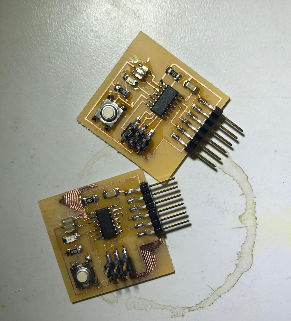
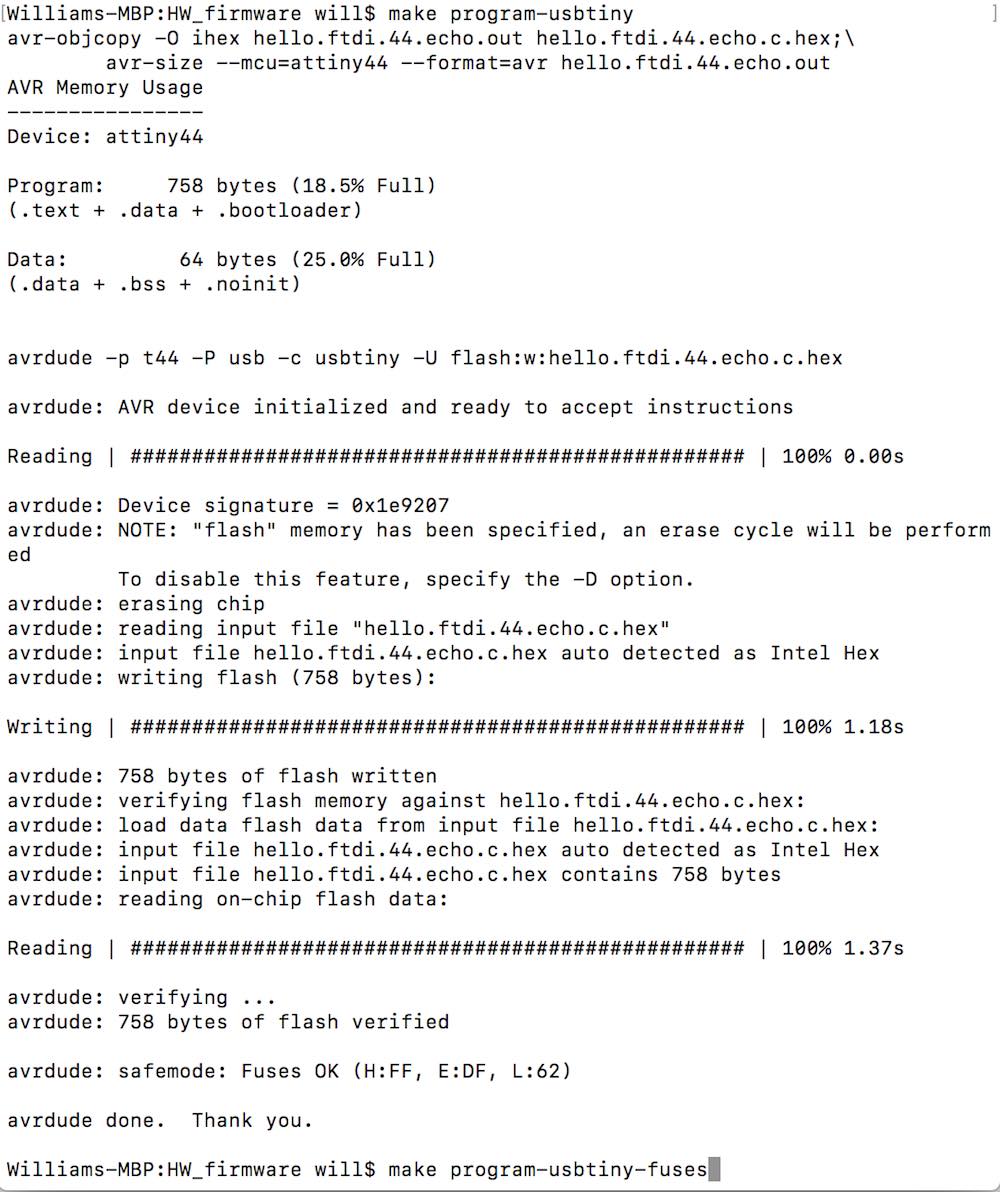
So all I ever got to confirm that this code actually worked was the verification of it uploading. I saw the video of it hooked up and communicating and just assumed the connection was a normal USB that was just broken out to its four seperate wires. Not sure if I missed some mention of FTDI communication or it hadn't been brought up yet and was just assumed knowledge. I even made my own broken out usb cable, spend far too much time fretting over wheter data + should go to tx or rx, and trying to communicate with my board to no avail. In retrospect it was a silly waste of time, though I did learn from it, if something isn't working, try to understand it more before plodding on too far. If I had just looked into communications protocalls, I would have realized pretty quickly that I was on the wrong track. I was informed by a collegue that what I needed was a FTDI to usb adaptor, a staple item of the lab. Spent enough time fiddling for now. Will get proper communications going in the following weeks. The board does seem to be working despite my naive attempts at connecting with it. I plugged power and ground backwards once and things got a little hot, but I quickly removed power, uploaded the code again, and it still seemed to flash.
To download my files click here: