Week - 11 Input Devices
About this Week
In this week we have to test the sensor in group and find out the analog and digital value of sensor for this we use ldr sensor for which we first go through the data sheet of ldr sensor
LDR Pin Description
The Light Dependent Resistor (LDR) is just another special type of Resistor and hence has no polarity. Meaning they can be connected in any direction. They are breadboard friendly and can be easily used on a perf board also. The symbol for LDR is just as similar to Resistor but adds to inward arrows as shown above. The arrows indicate the light signals.
LDR Features
Can be used to sense Light
Easy to use on Breadboard or Perf Board
Easy to use with Microcontrollers or even with normal Digital/Analog IC
Small, cheap and easily available
Available in PG5 ,PG5-MP, PG12, PG12-MP, PG20 and PG20-MP series
Other Resistor based Components
Higher Power Resistor, Potentiometer (Variable Resistor), Thermistor.
Where to use a LDR
A photoresistor or LDR (Light Dependent Resistor), as the name suggests will change it resistance based on the light around it. That is when the resistor is placed in a dark room it will have a resistance of few Mega ohms and as we gradually impose light over the sensor its resistance will start to decrease from Mega Ohms to few Ohms.
How to use a LDR sensor
As said earlier a LDR is just like a resistor, hence using it is very easy. There are many ways and different circuit in which an LDR can be used. For instance it can be used with Microcontroller Development platforms like Arduino, PIC or even normal Analog IC’s like Op-amps. But, here we will use a very simple circuit like a potential divider so that it can be adapted for most of the projects.
Applications
Automatic Street Light
Detect Day or Night
Automatic Head Light Dimmer
Position sensor
Used along with LED as obstacle detector
Automatic bedroom Lights
Automatic Rear view mirror
Please find attached the data sheet here
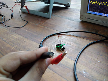
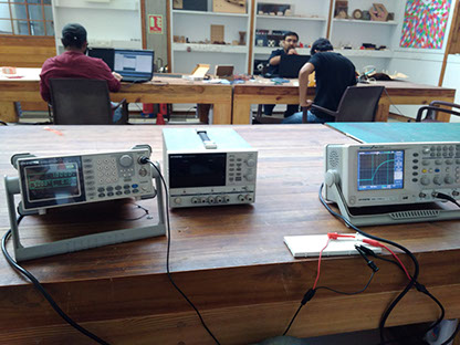
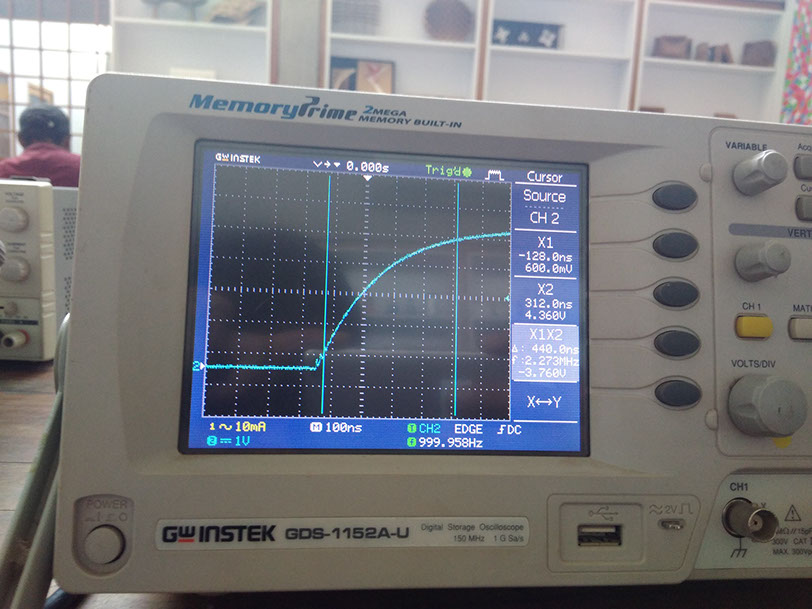
We are using the function generator for getting graph between the time and voltage we use machine gentak AFG-2125 and oscilloscope we want to find out various value in it
About the machine
Function generator
A function generator is usually a piece of electronic test equipment or software used to generate different types of electrical waveformsover a wide range of frequencies. Some of the most common waveforms produced by the function generator are the sine wave , square wave, triangular wave and sawtooth shapes. These waveforms can be either repetitive or single-shot (which requires an internal or external trigger source. Integrated circuits used to generate waveforms may also be described as function generator ICs
Function generators are used in the development, test and repair of electronic equipment. For example, they may be used as a signal source to test amplifiers or to introduce an error signal into a control loop. Function generators are primarily used for working with analog circuits, related pulse generators are primarily used for working with digital circuits
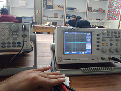
Oscilloscope
An oscilloscope, previously called an oscillograph,and informally known as a scope or o-scope, CRO (for cathode-ray oscilloscope), or DSO (for the more modern digital storage oscilloscope), is a type of electronic test instrument that allows observation of varying signal voltages, usually as a two-dimensional plot of one or more signals as a function of time. Other signals (such as sound or vibration) can be converted to voltages and displayed.
http://www.gwinstek.com/en-global/products/Oscilloscopes/Digital_Storage_Oscilloscopes/GDS-1000A-U
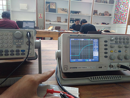
With this you can find the vrms ,vamp, width , rise time which are the essential value of component you generally found in any data sheet of project.
In this we need voltage divider circuit in this for this we use breadboard and connect this sensor with machine as shown measure the value
The various value which we find out
During ldr sensor in visible light
vAPP-3.69v
Vrms-1.73v
Rise time 1.8ns
Conclusion
In this week we successfully learn use of oscilloscope and measure the corresponding value of input sensor using them function generator

