I have embarked on reproducing Daniele Ingrasia's Satstep stepper motor driver for both my output devices week and for my final project which will involve several stepper motors.
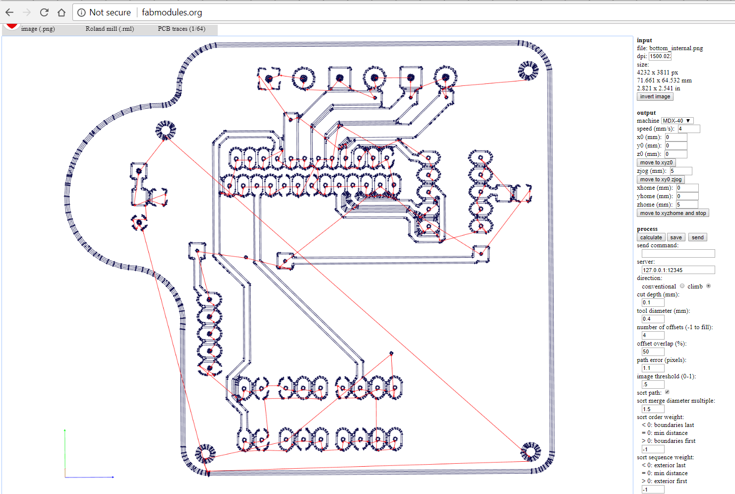
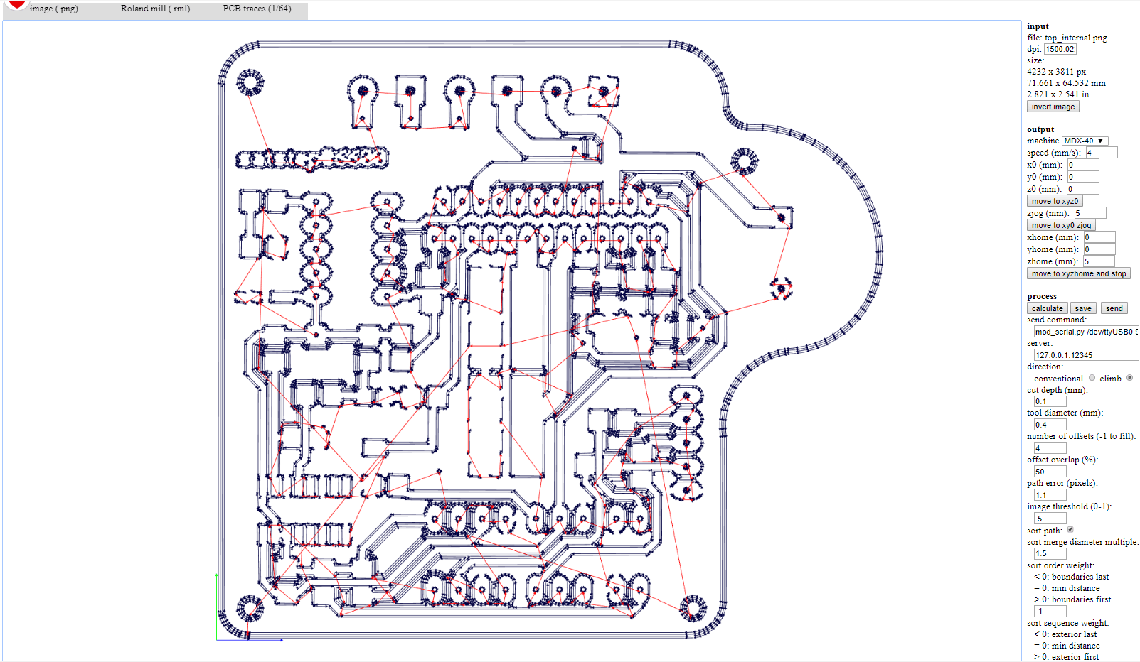
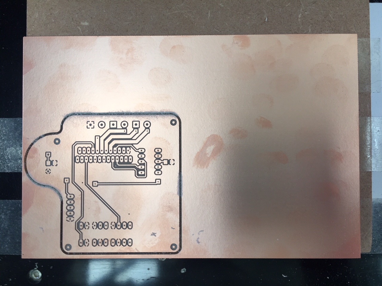
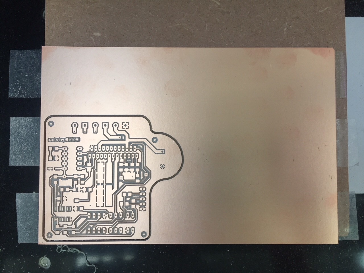
I downloaded Danieles files from his github page which includes a bill of materials the eagle files and the .png's required to mill the board using 0.1 and 0.4mm bits. I am going to use the 0.4mm traces.
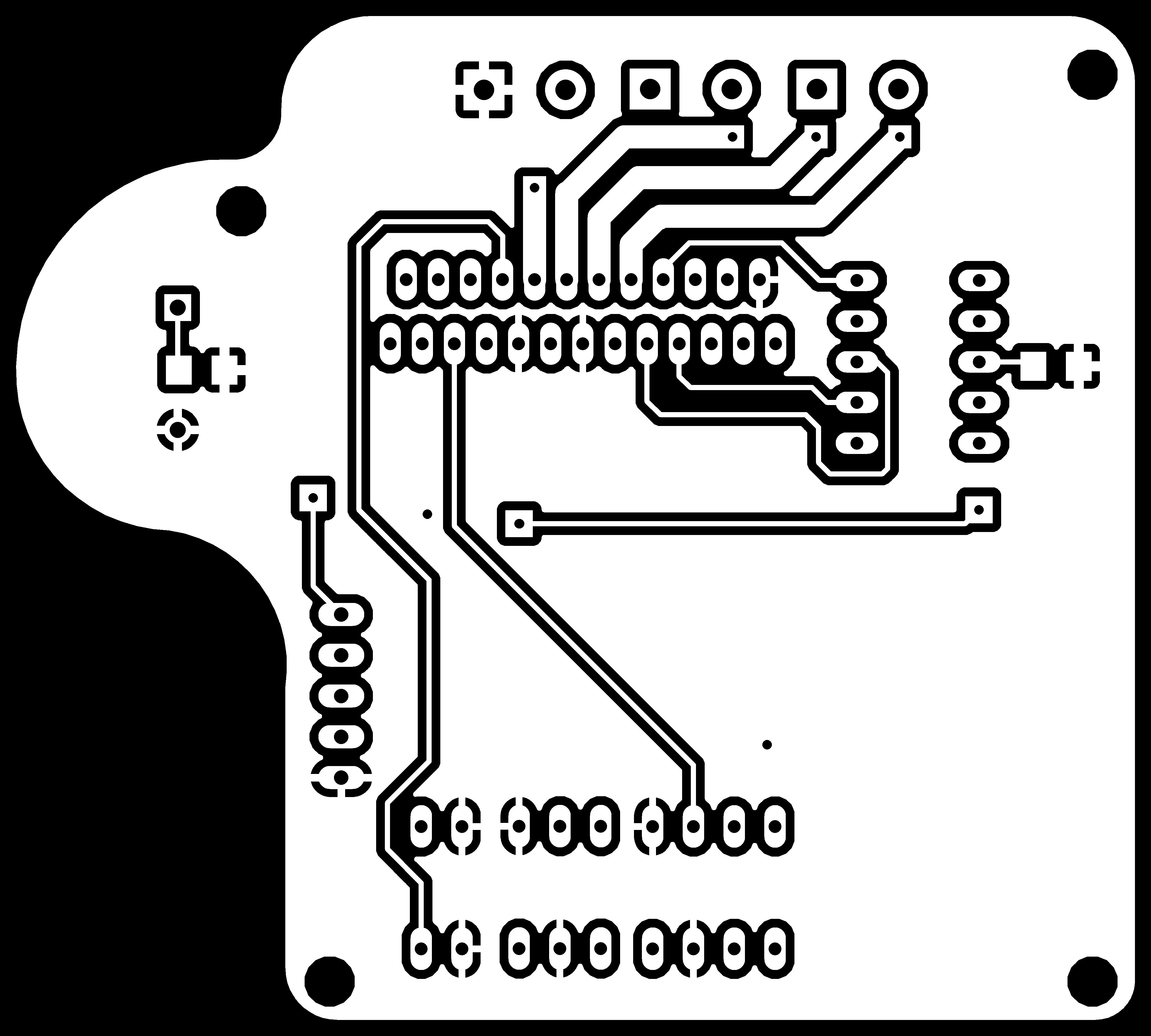
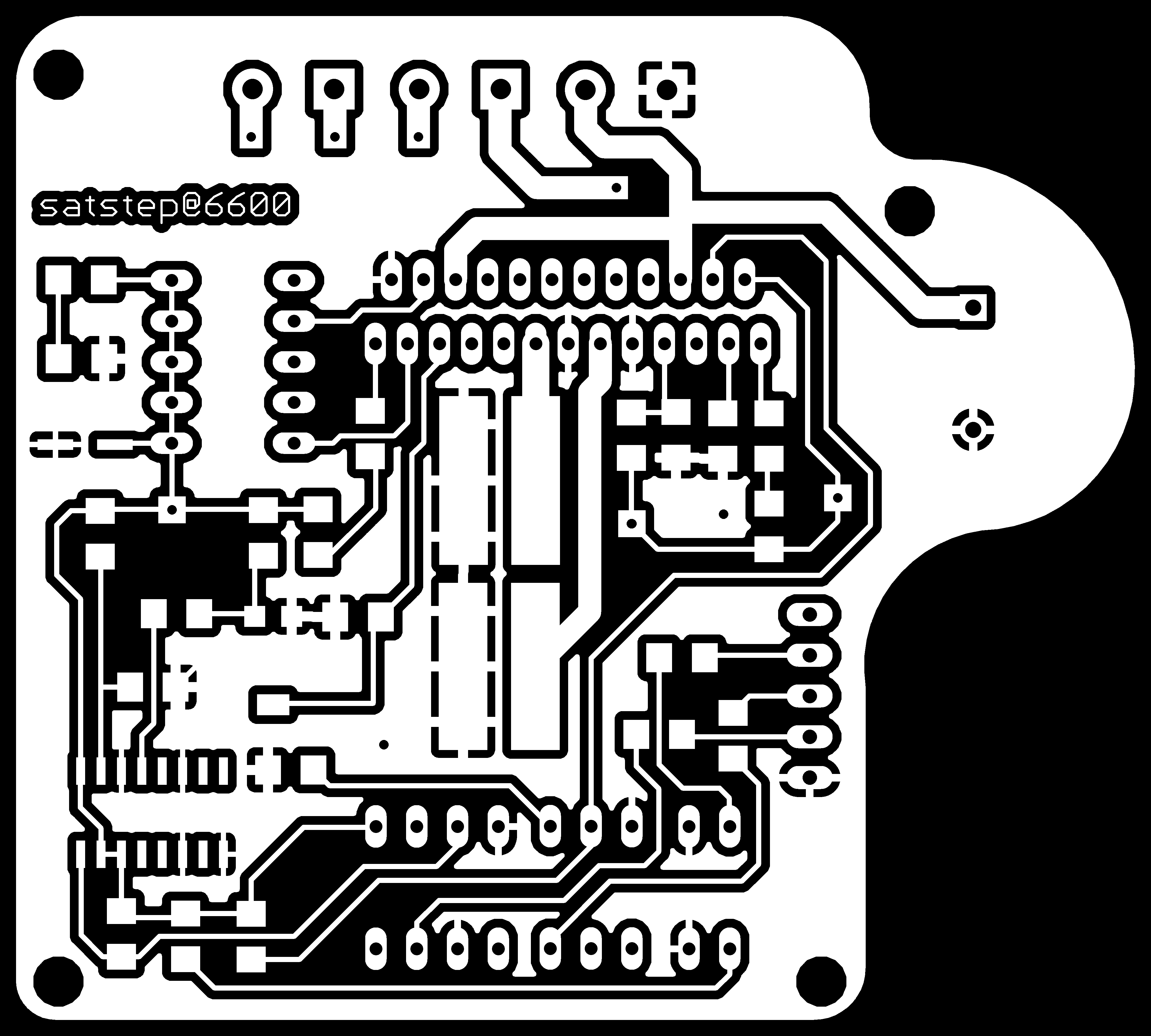
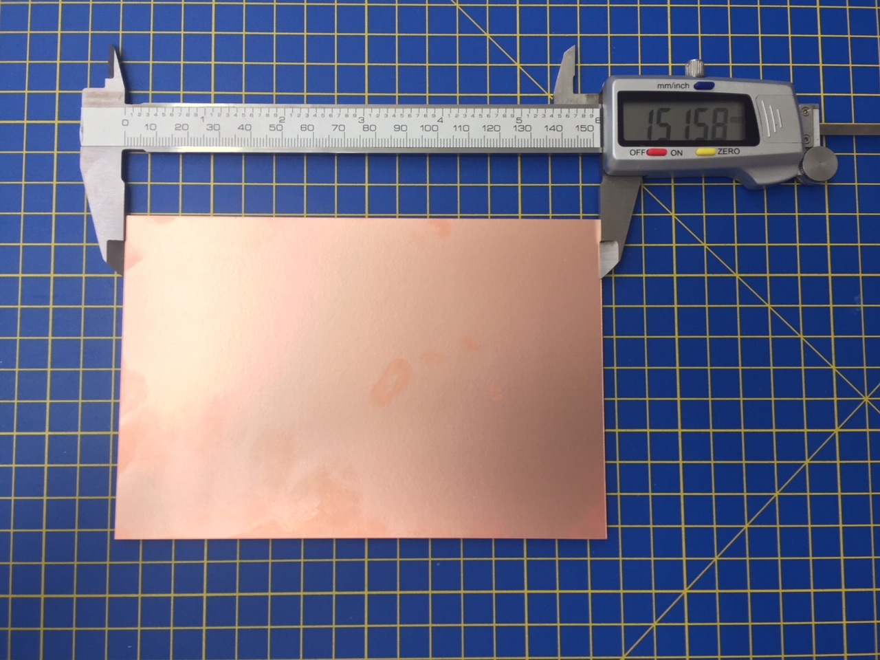
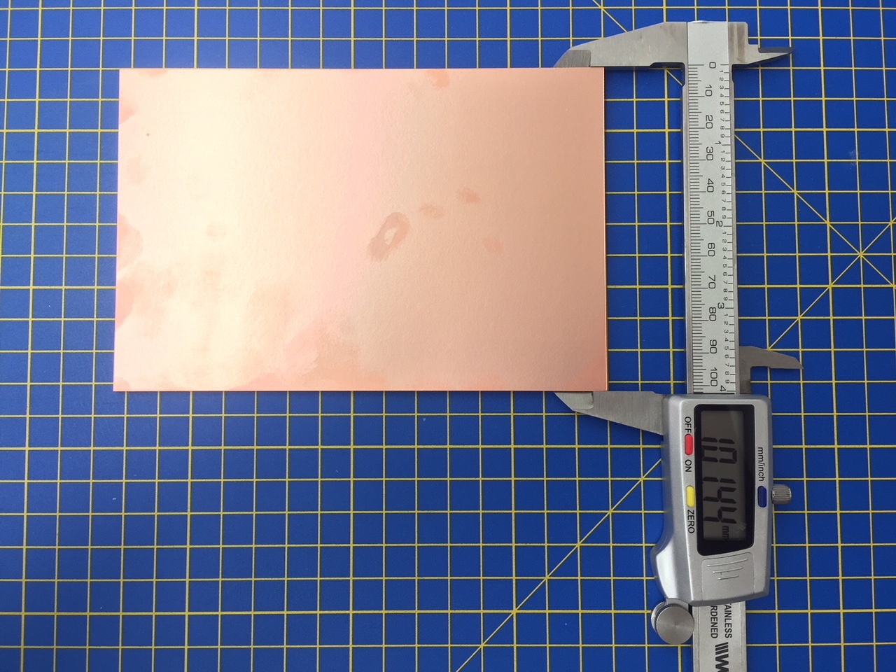
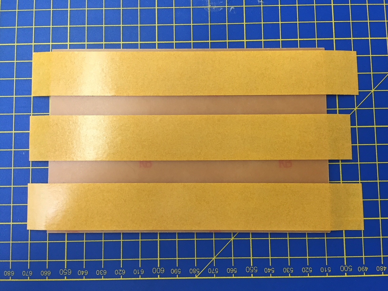
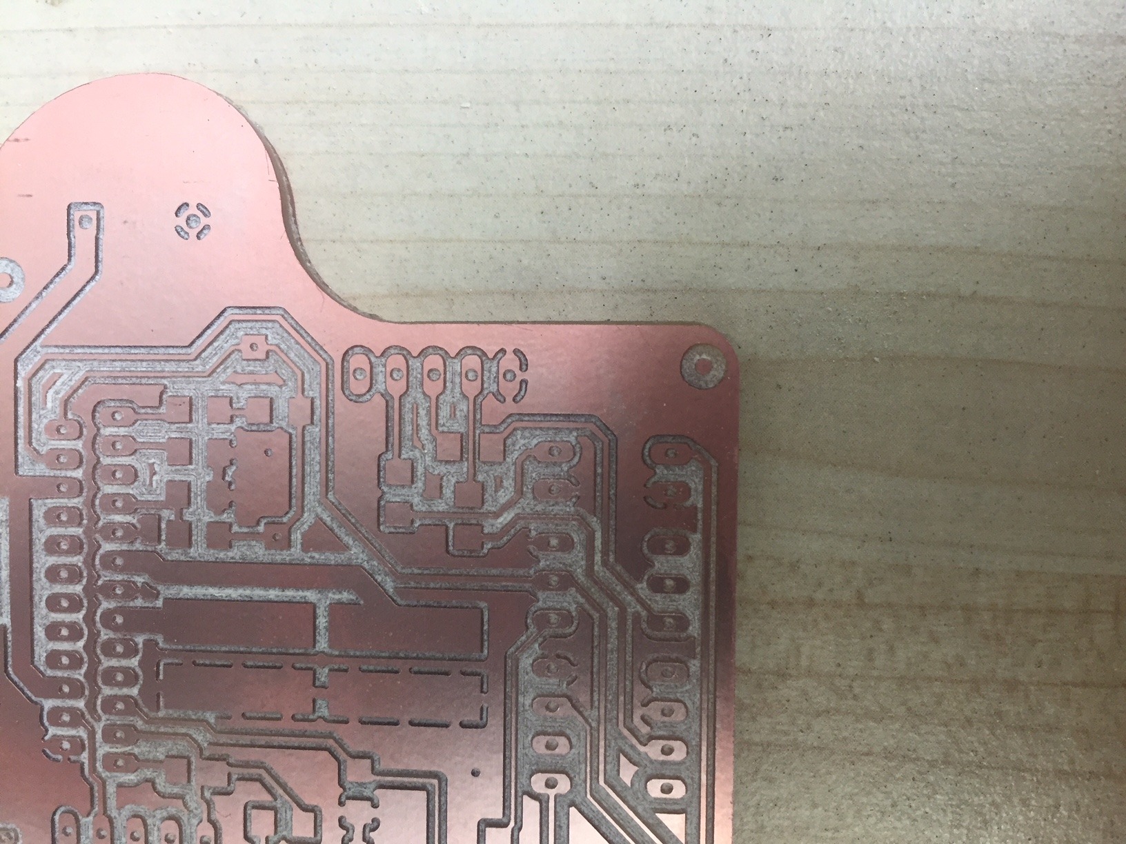
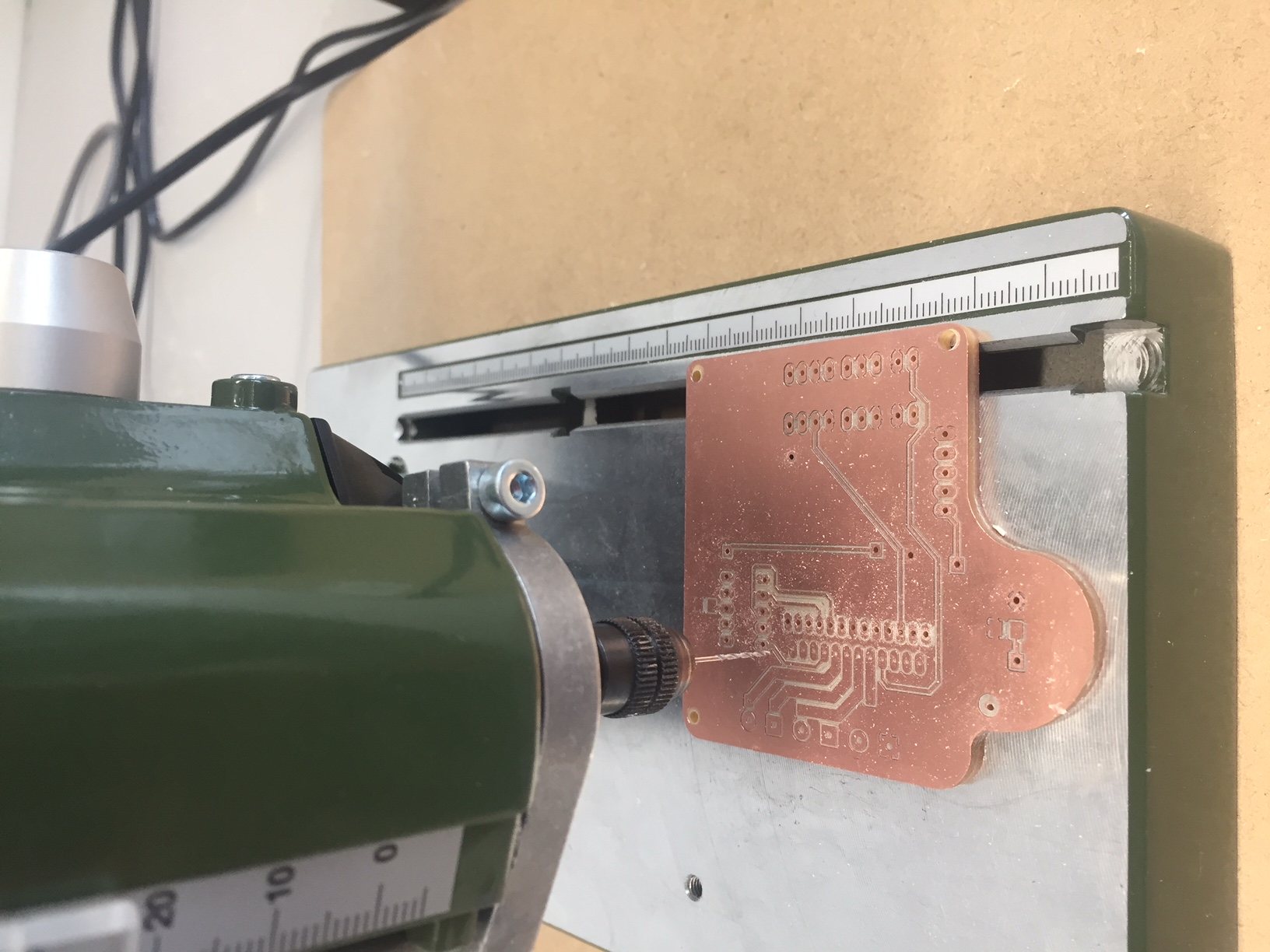
For this board I have to use the large PCB's as it measures approximately 70 by 65mm
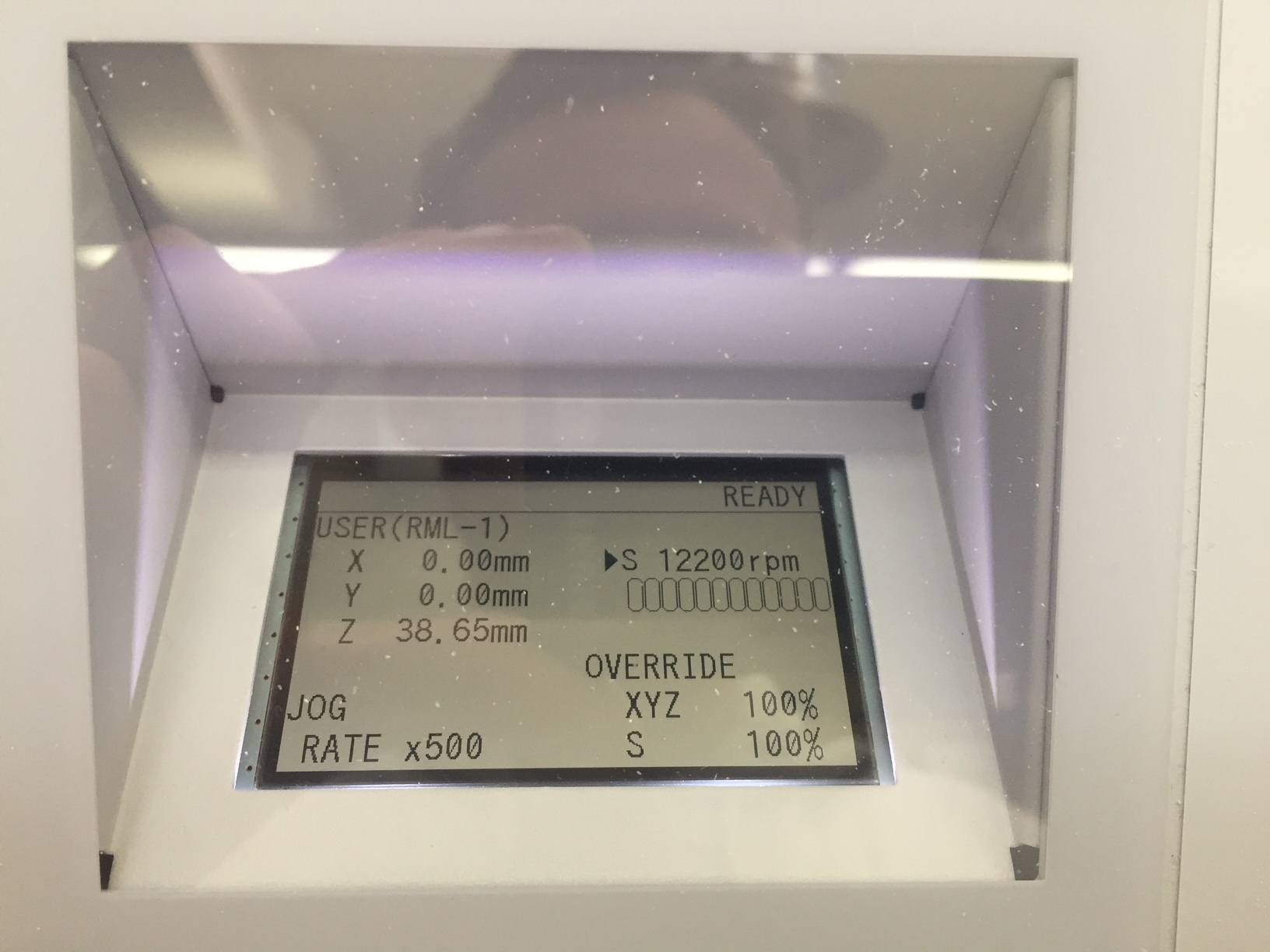
The spindle speed will be 12500 RPM
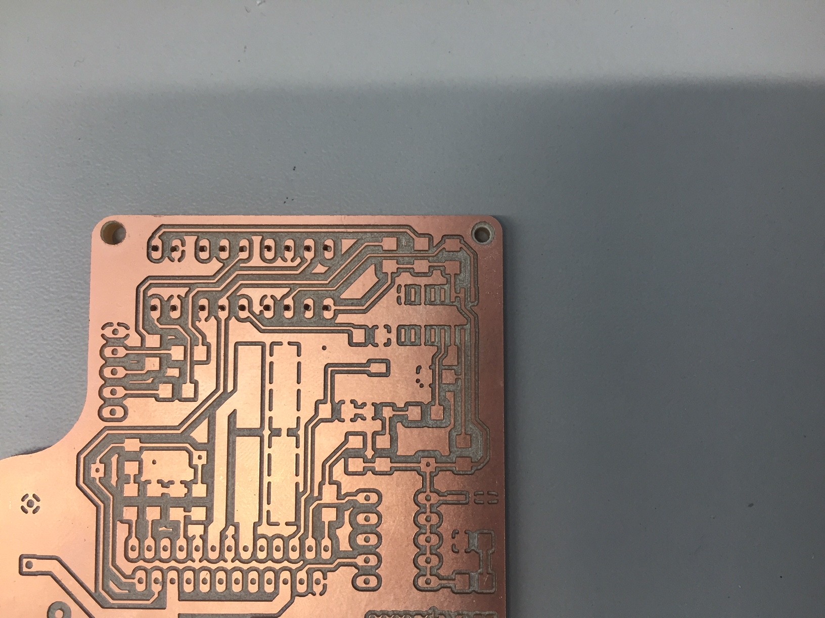
So far so good! Looks like it should.
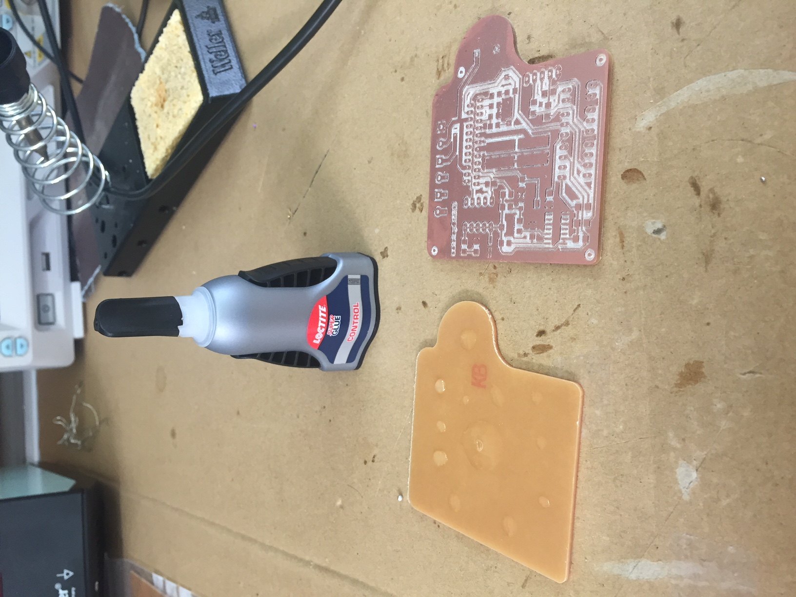
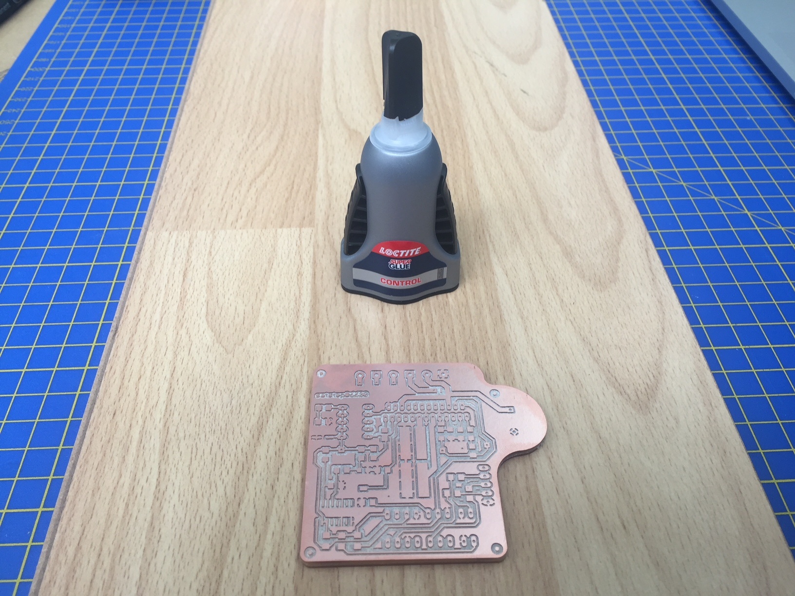
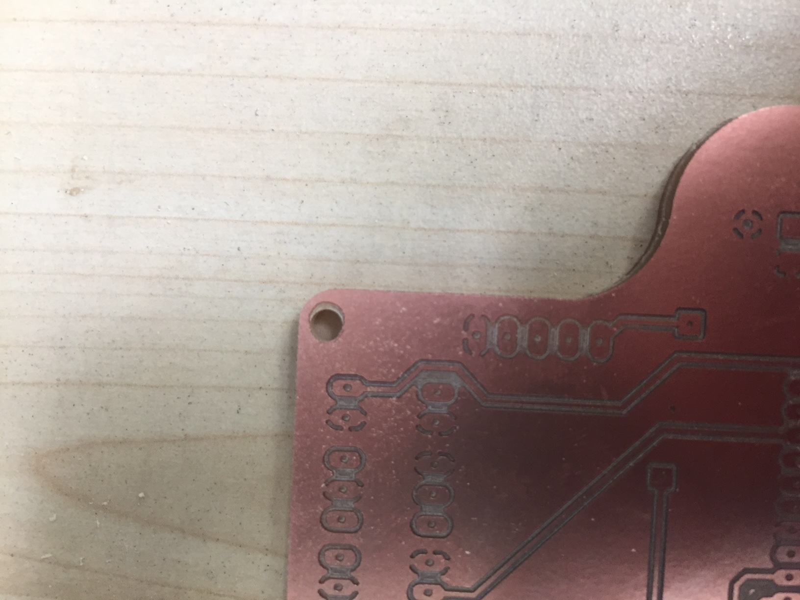
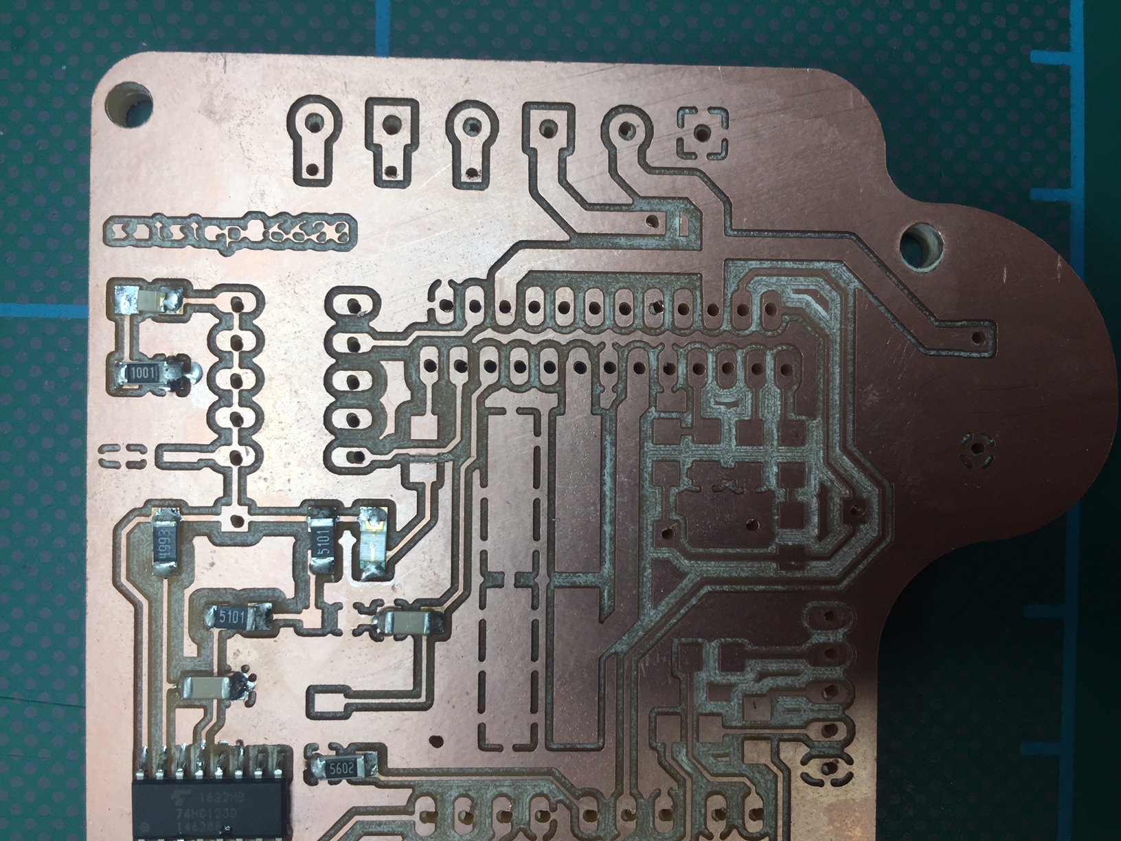
The next step was to stick the boards together and drill the holes for the through hole
components.
I used Locite super glue as it was available and simply stuck the two boards together after spreading the glue and aligning using the flat edges.
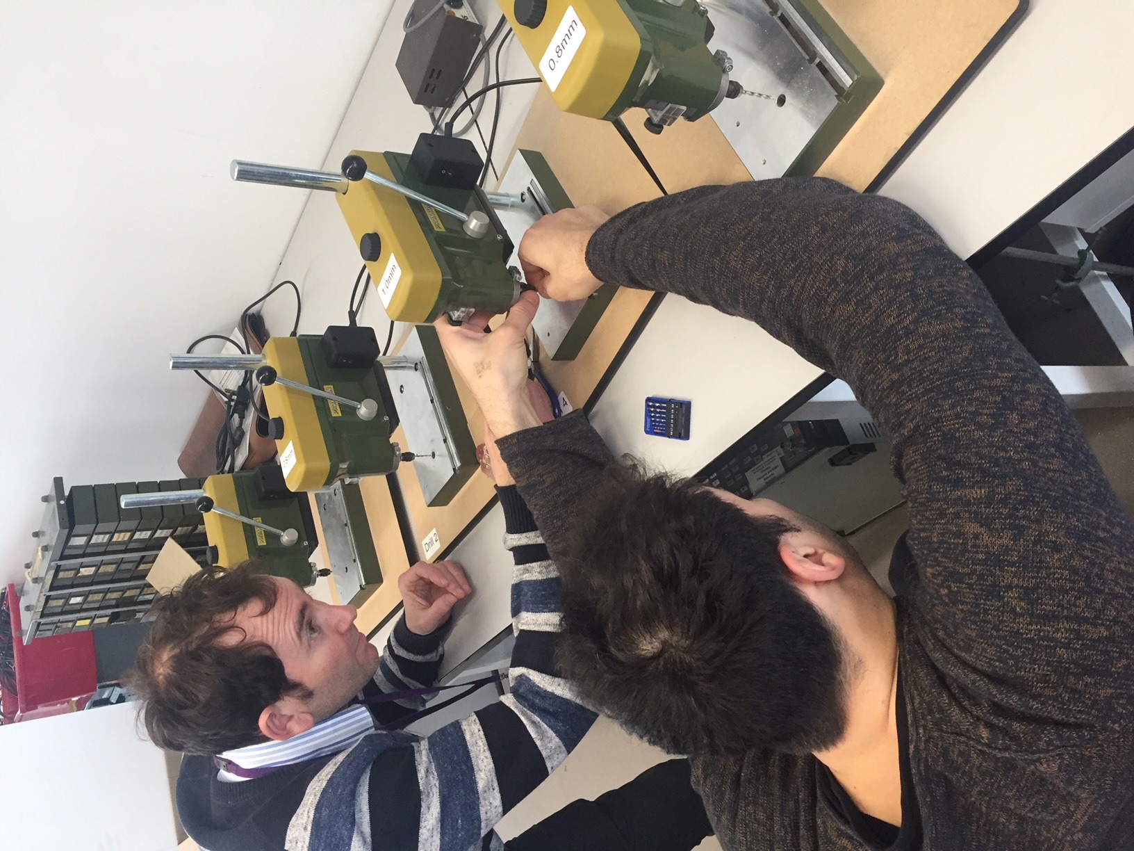
We have a Dremel in the lab with a pillar drill attachment. It looked as though it vibrated a lot and the hole on the other side was slightly offset - I though - due to excessive vibration. I was wrong however and I found that I had simply mis-alinged the two boards when sticking them together. In future I will create a file to mill out these larger outer holes and use these to align the two boards together. Unfortunately we only had the collet available for the Dremel to mill these larger holes which I used a 2.8mm drill bit for.
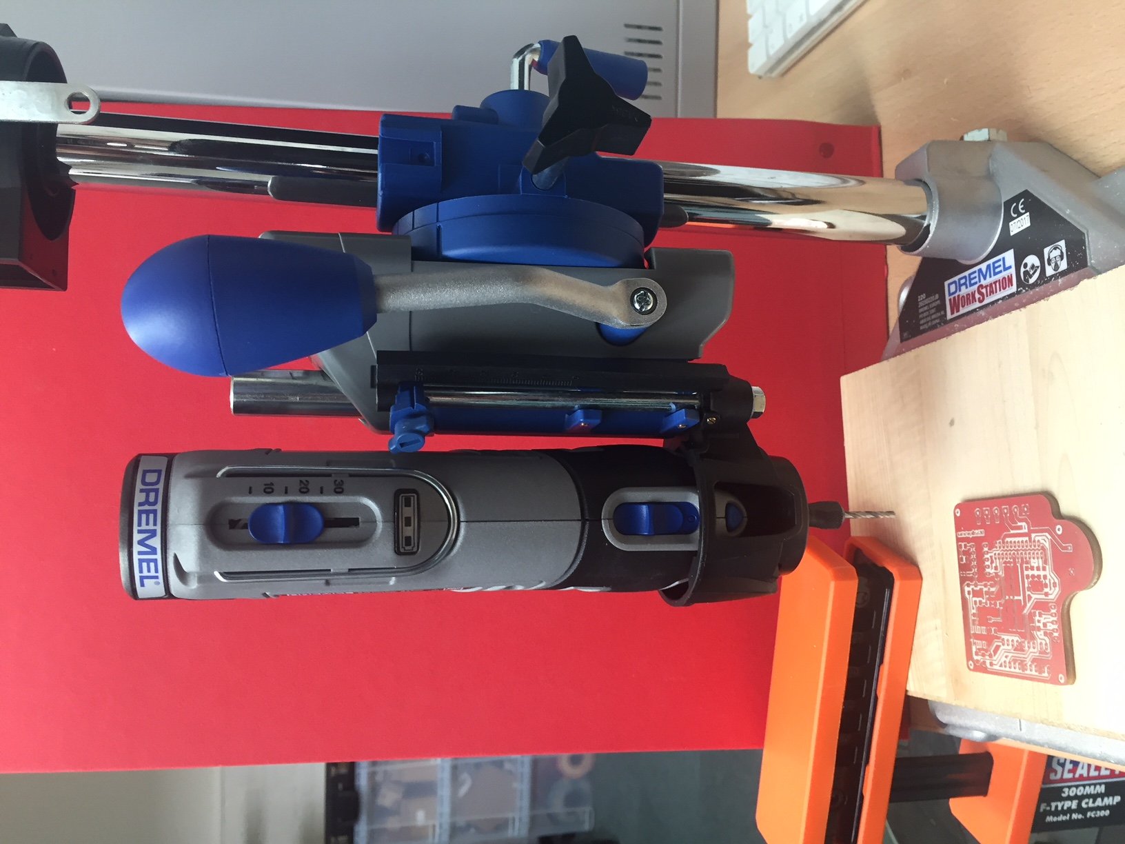
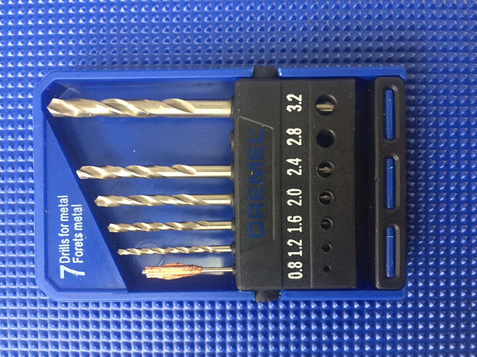
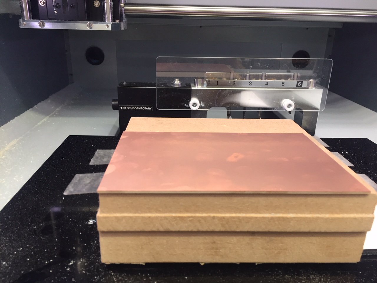
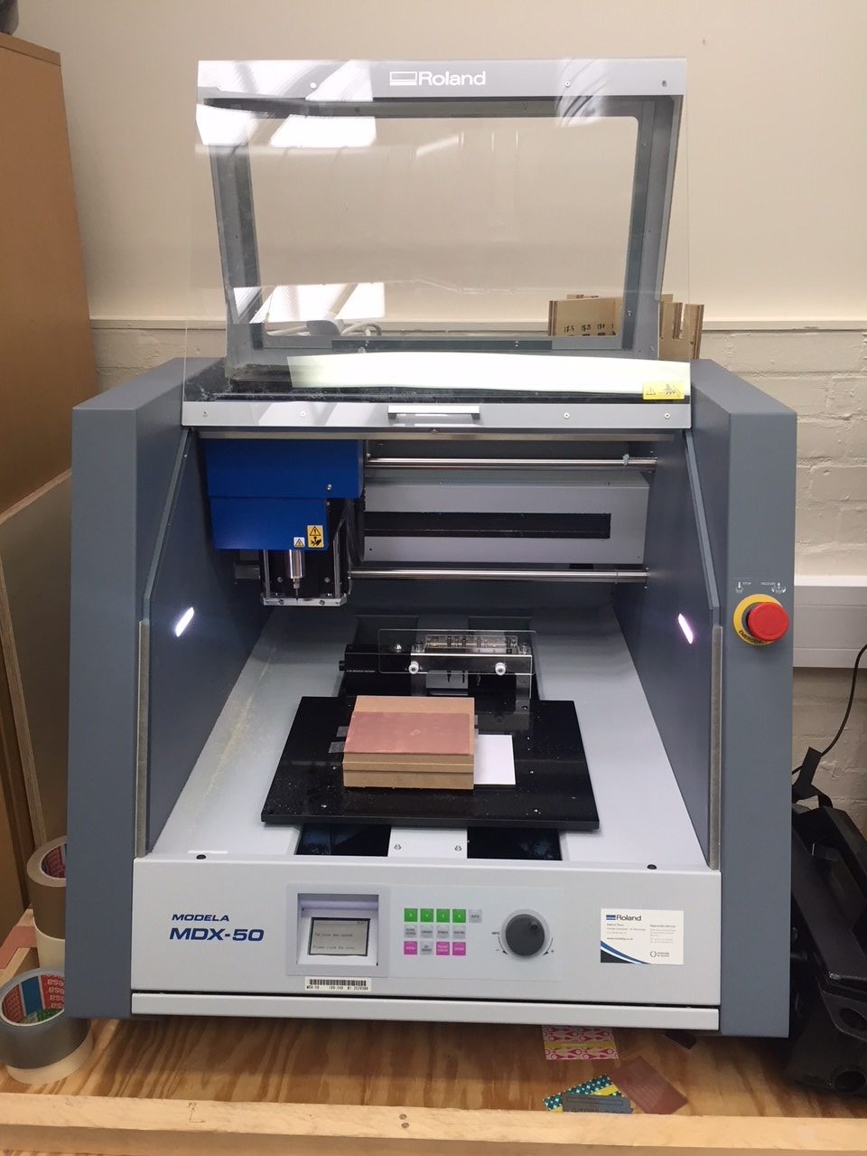
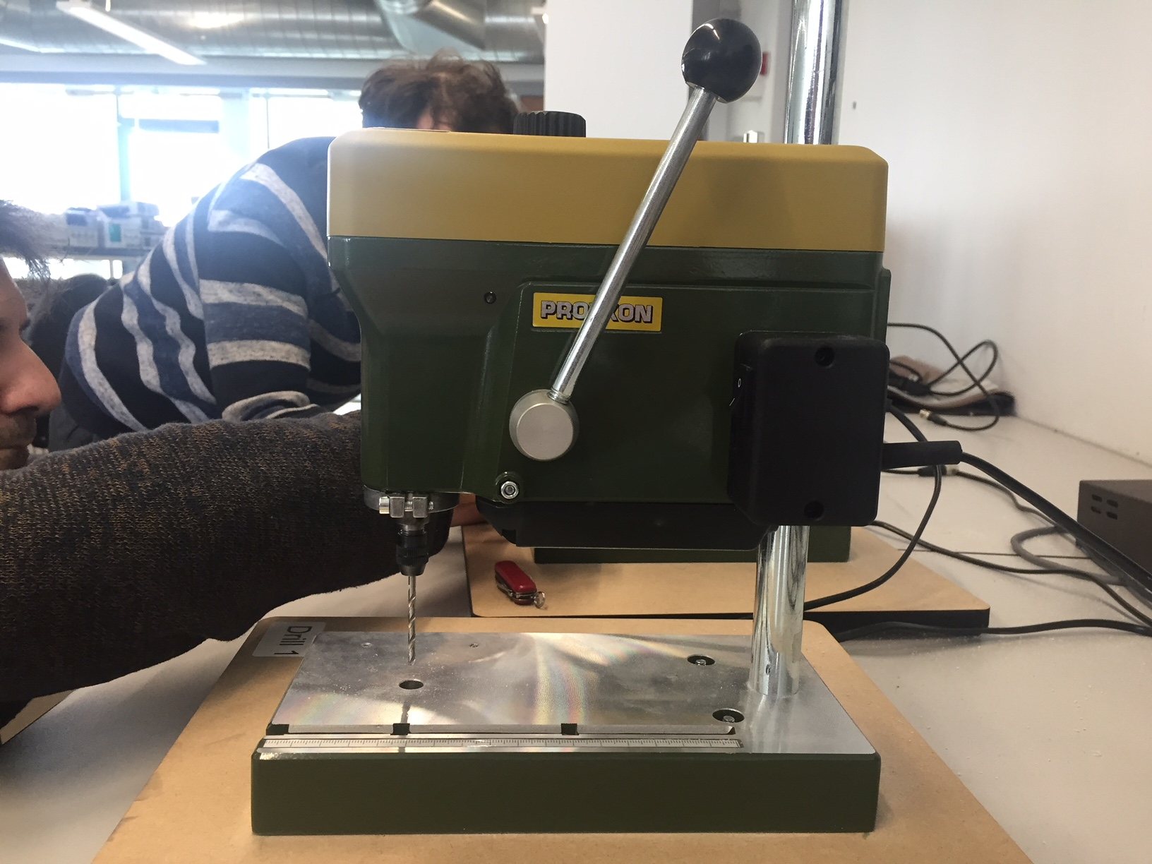
Fortunately we are located in a well equipped university and one of the electronics labs had these excellent Proxxon mini pillar drills. I used these to mill out my remaining holes using a 0.8mm drill bit. The misaligned boards was evident again and the holes were slightly offset on the other side to where I drilled again showing the importance of proper alignment. Luckily I don't believe this will cause issues, but with future boards I will not take the risk. I am also going to use a 1.2mm drill bit to drill out the large cable connector holes
Next it was time to place the components. Laying them out made the whole board feel much less daunting. The through hole
components fit perfectly through the 0.8mm holes and there didn't seem nearly as I thought there would be. I bought these components well in advance as I knew I wanted to make this, unfortunately I have forgoten the 0.68Ohm 2512 package capacitors so I will have to wait for these to arrive before the board is finished.
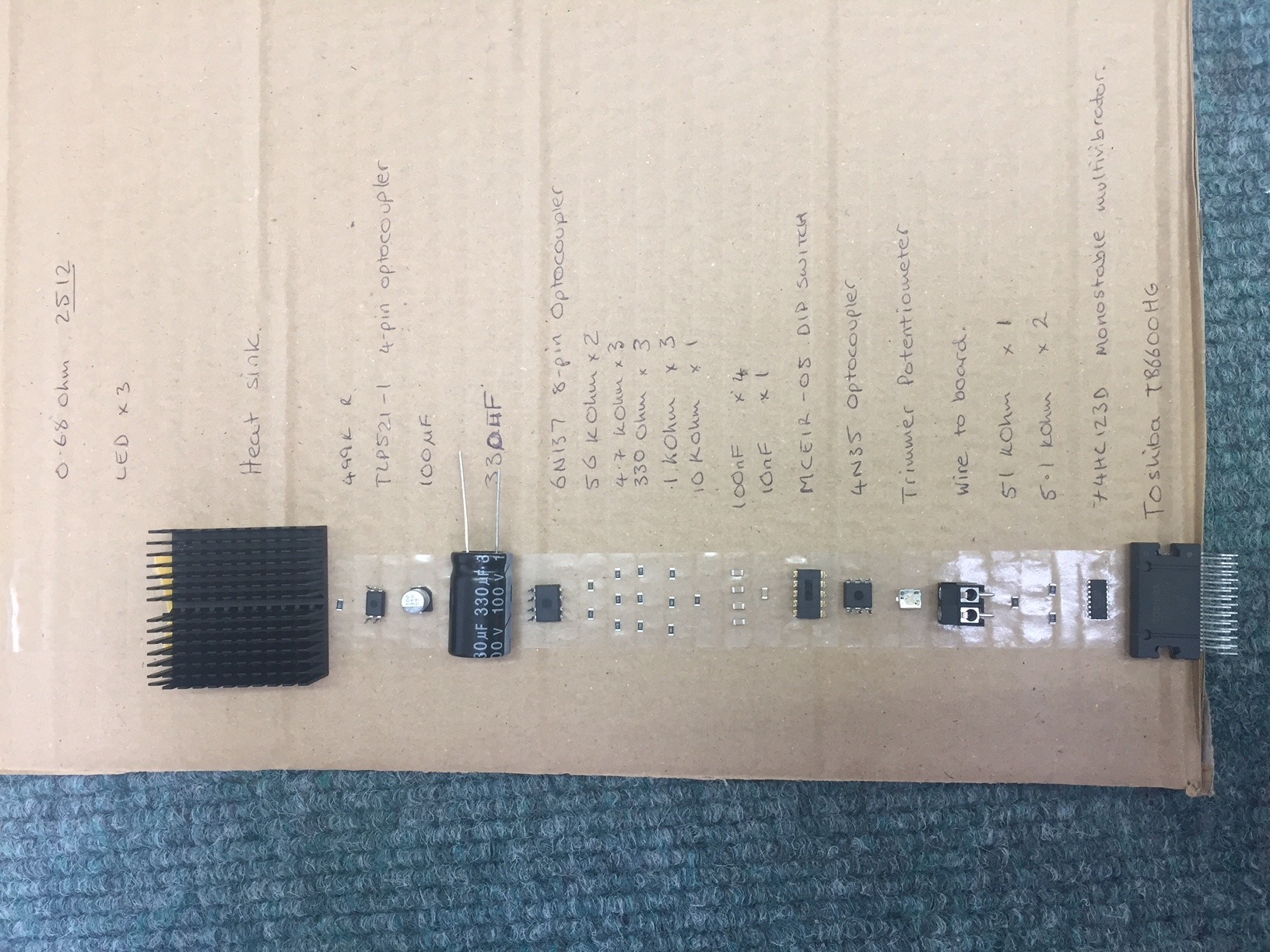
The missing resistors arrived in good time and I got to soldering. Daniele advised I started with the smallest components first and then work up in size to the largest components.
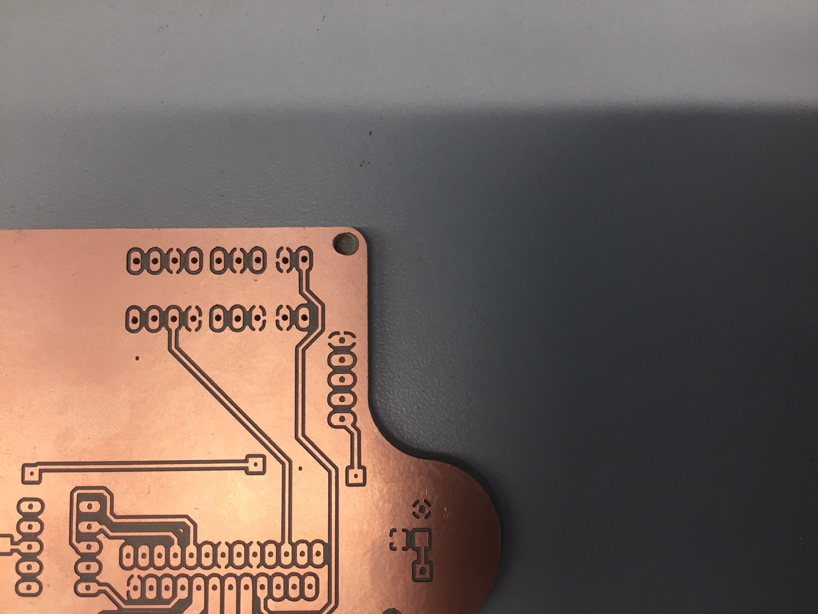
I used the 0.4mm files that are in the Satstep download files. They were all very easy to use, however one of the traces didn't mill out. Looking at the eagle files it would be an easy fix by readjusting its position between the two resistor pads.
The next challenge was milling the Toshiba chip. One issue is the heat dissipation capabilities of this chip meaning it was difficult to heat the pins up enough to bond the solder to them. My other challenge was the two rows of pins - getting to the ones at the back was very difficult with the tip I was using; this combined with the heat dissipation concluded in a bit of a mess.
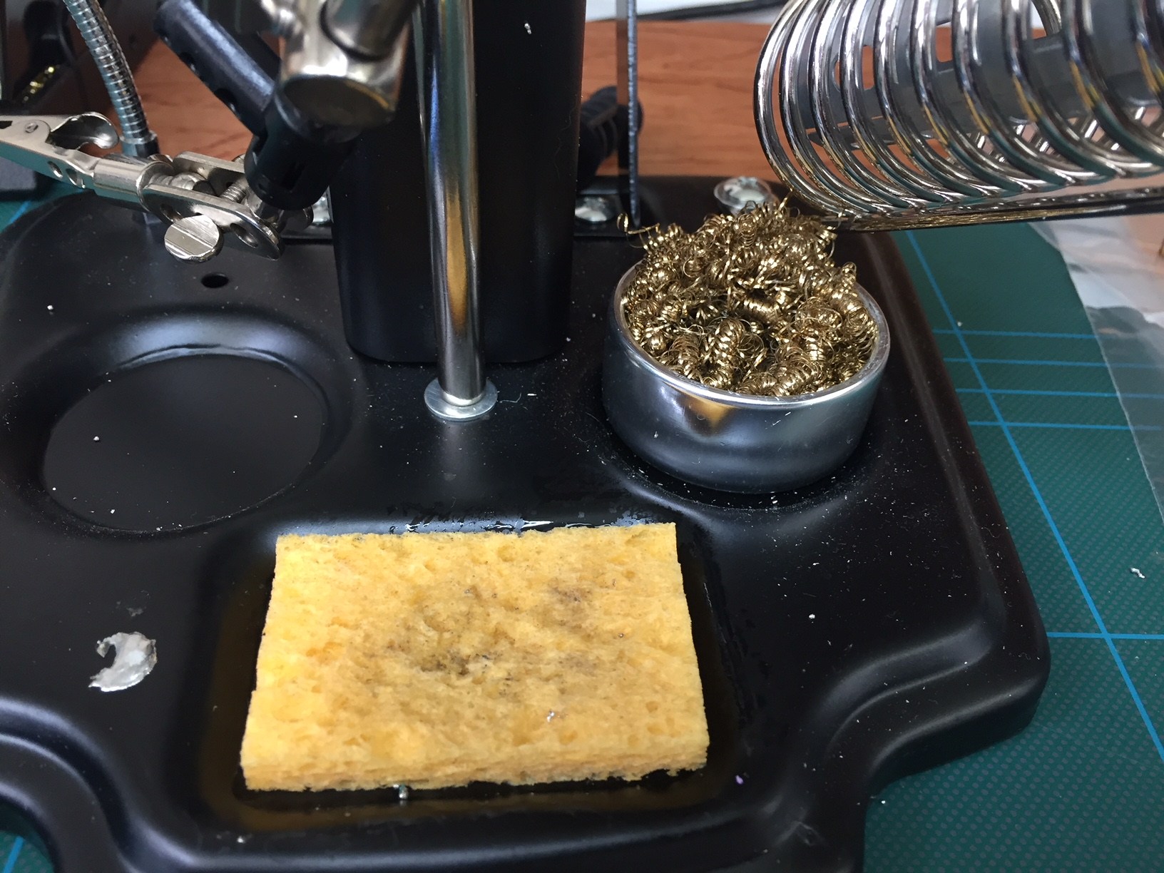
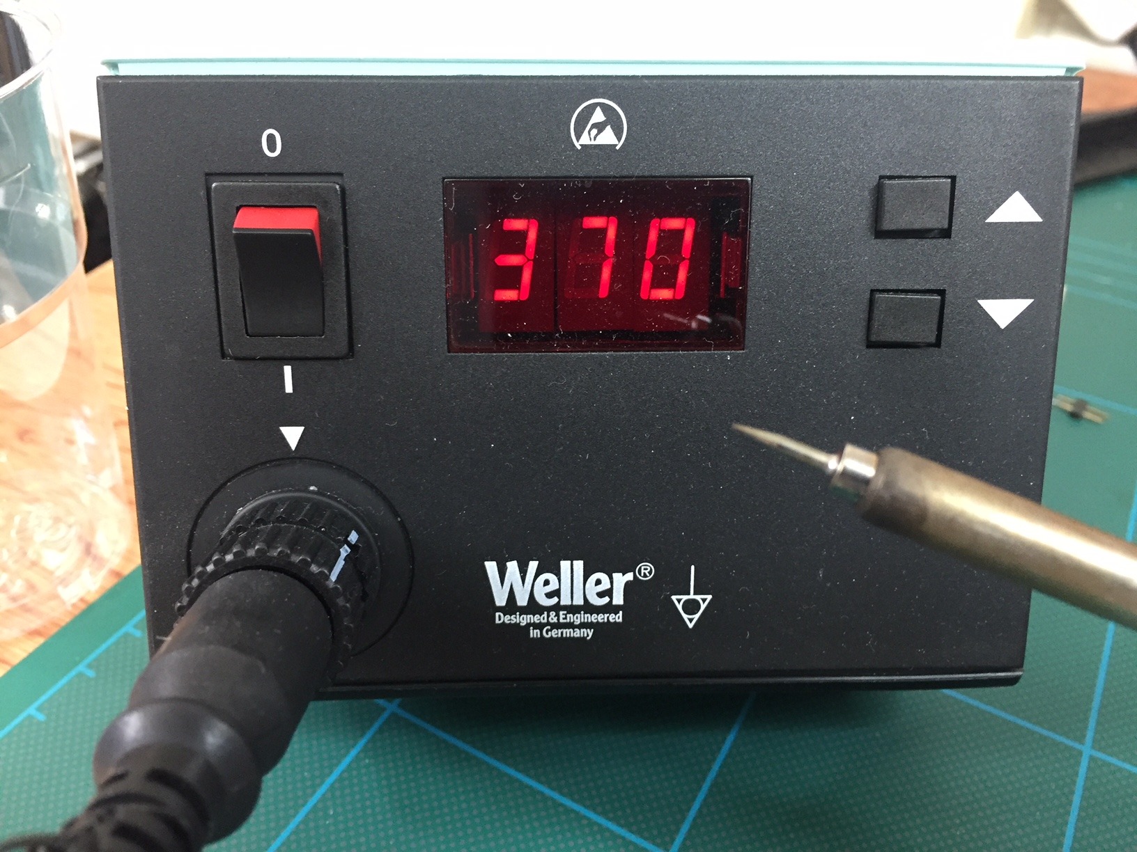
To over come this (and after a fair bit of solder braid and solder suckering) I found our bag of tips some of which had much narrower heads to get into the small gap. I also turned the temperature up from the usual 350 to 370. This meant my tip oxidised much quicker negating any increases so plenty of damp sponge and wire wool usage was required. Finally (I am not sure if this helped or not) I held a small piece of MDF against the heat dissipation area of the chip to stop the heat loss I was experiencing.
PICTURE OF CHIP ON BOARD REQUIRED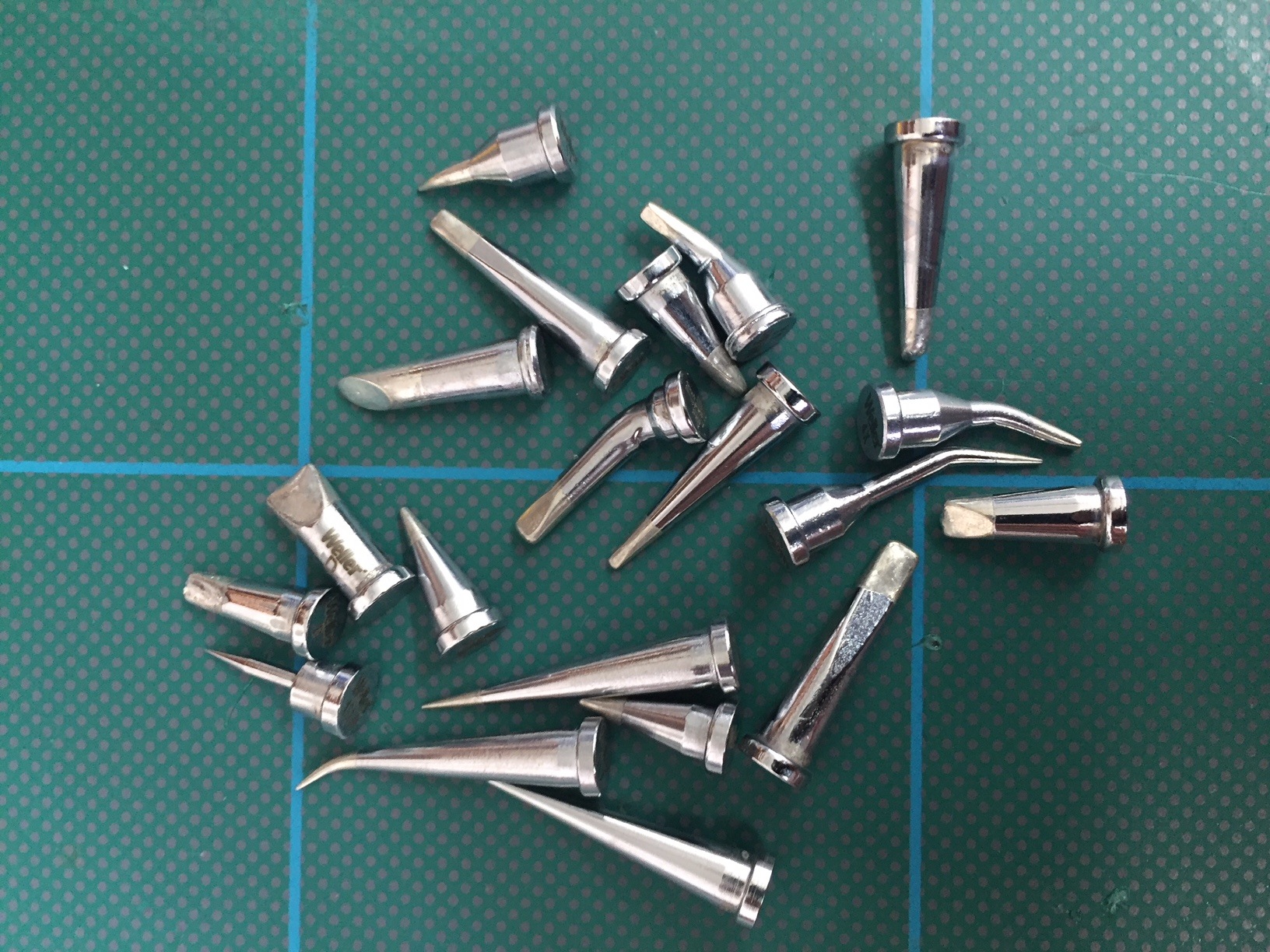
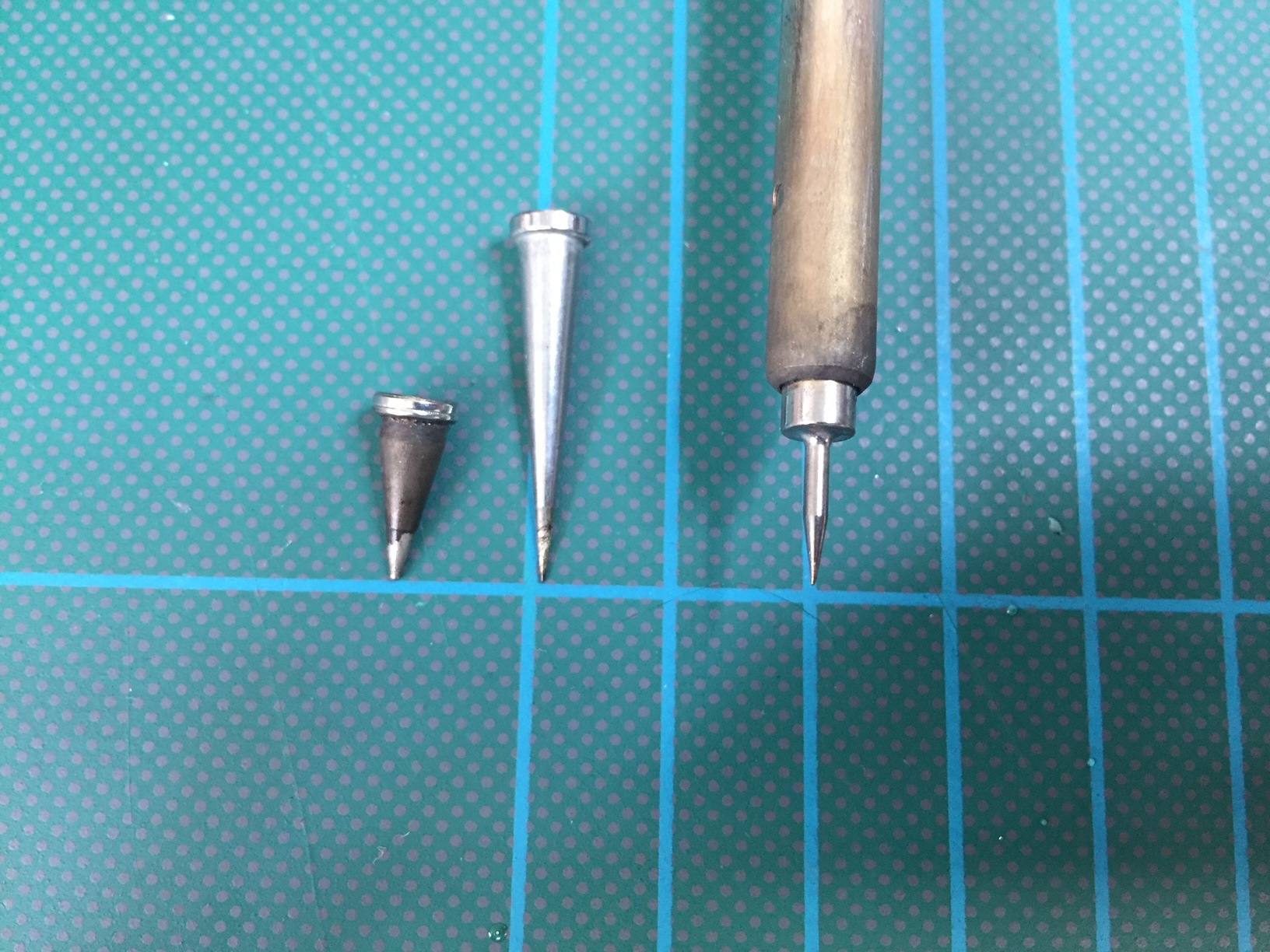
The tip on the left I was using origionally, the second I tried, but I found the heat was lost with the length of the tip. The third, along with my other techniques worked a treat.