As I am jumping ahead a couple weeks on the programming I followed one of the tutor's documentation(Arnau) from last year.
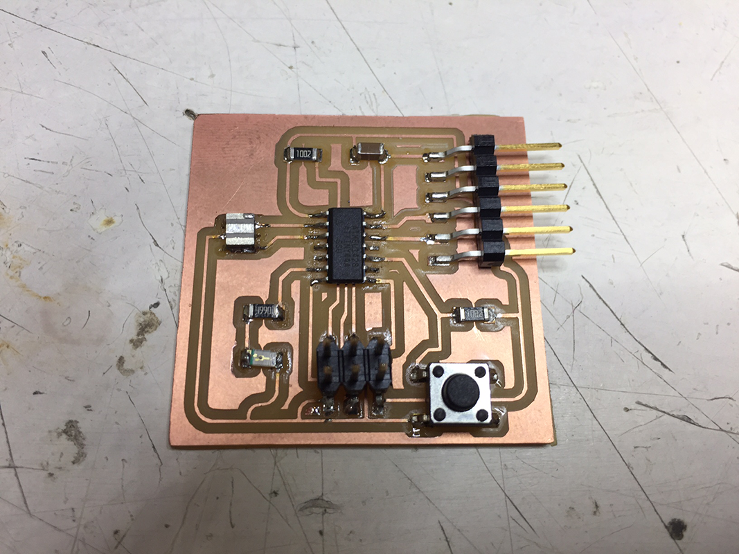
This week we are programming the board we made in week 6 to do something. aka make the LED flash.
I have played a bit in Arduino before and had some experience in other languages, but it was all a while ago and not in great depth. From what I understand most languages we are using are just simplified forms of the C coding language. It is possible to code directly in C, but to start with I will be using the Ardunio language and interface.
To begin coding it is useful to know the physical layout of the microcontroller which is where the Attiny data sheet comes in handy.
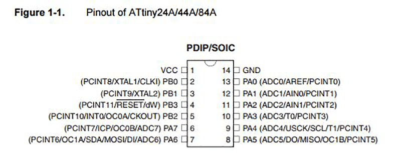
The data sheet is full of information and I can see it being very useful for other components in the future for working out how to connect and program microcontrollers. For this week knowing the use of and which pins I have connected is enough.
I can see my MOSI, MISO are connected to pin 6 and 5. My reset and clock pins are 4 and 9. Finally my Ground and Power are pins 1 and 14. I need to know these to connect my programmer and burn the bootloader and be able to program the board.
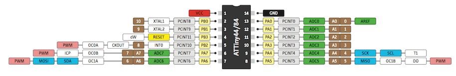
I now know my LED is connected to pin 6, which for arduino programming can be considered pin 7.
To start the process I had to remove my 0 Ohm resistors from my FabISP enabling it to program other boards. This was where my first error occured. In my haste I accidently removed a 10k resistor and a 0 Ohm resistor. This was easily fixed however.
Next I moved onto setting up Arduino for programming my hello_board. I had to download the Arduino IDE 'Integrated Development Environment' to be able to code and upload using it. Next I had to add the Attiny package to Arduino as it is not included in the Board manager as default. To do this I went to Arduino > Preferences and in the 'Additional Boards Manager URLs' I inserted "https://raw.githubusercontent.com/damellis/attiny/ide-1.6.x-boards-manager/package_damellis_attiny_index.json". Next was to go to Tools > board > board manager and then scroll down and install ATTINY.
To burn the bootloader I used the following settings (using a FABISP) in Tools and then hit 'Burn Bootloader
The board connections required me to connect my FABISP to one USB port (it will not show up in Arduino), connect my FABISP via the six pin header to my hello board and finally I need to power my Helloboard via the FTDI pins. For this I used an Arduino UNO 5V output.
I followed the steps and checked over and over again, but I was always getting an error message when trying to flash the board. I got on a MAC and I was succesful. The same thing happened when I tried to program the board to flash using a couple of basic scripts premade by arduino. Again the solution was using a Mac. I still need to investigate what is stopping me from using windows to succesfully program my board. I did this using both my FabISP and the ISP I used to program my FabISP so it was not a hardware issue. I also tried the current Arduino version 1.8.1 and an older version 1.6.8.
I was succesful when using a mac however. I initially had an issue with my LED. I had either put it on the wrong way round or it was faulty. I had checked online for the polarity and it matched what I had done, but it was a red LED which I read may sometimes have the polarity markers in the opposite direction. Once replaced I succesfully uploaded the basic 'Blink' and 'Fade' programs from the Arduino IDE.
Colleagues in my class using windows have had the same issue when trying to program their hello_board. After much head scratching and hair pulling we eventually found a solution all the way from Norway. Thank you Jakob Nilsson. It turned out we had to install some drivers for various components including the fabISP and the FTDI cable.
With this installed I was on my way to a succesfully blinking board.
I used the standard blink program (dowloadable below) which can be found in the basic examples in the Arduino IDE. I had to change the pin the arduino was sending the signal,(from LED_BUILTIN) to pin 7 as my pin was connected to 'pin 6' on the ATTINY, but this translates to pin 7 for arduino (as per the image above). This is then defined as an 'Output'. This is in the 'setup' part of the code where we define pin numbers and function and any variables we might be using later.
Here is the blink program running on the arduino
The LED in this example has two states, On and off, or as arduino understands it 'High' and 'Low' repectivley. As these are binary values, they are considered digital. The next part of the code is the 'loop' which will continuosly run over and over. In this next part, we 'digitalwrite' to the pin we set above and define it either High or Low. In between there is a delay. Arduino understands time in milliseconds, so 1000ms = 1 second.
Here is a nice link that explains the arduino code layout further using the blink example.
To send the code to the board we need to 'compile' which basically checks the code against the settings such as processor we are using and any errors in the code. Once this has passed we can click upload and the code is sent to the board.
It is important to note that I still require my FABISP to send programs to my hello board as the FTDI TX/RX is not enough. These are here so I can communicate with my board.
I also edited the Arduino basic fade example to work with this board, changing pin type and fade time. This works with 'analog' variables and the effect can be seen in the video below.
The 'analogewrite() funtion uses PWM (Pulse Width Modulation) to imitate an analog signal. Ths is because the Arduino does not have a built in digital to analog convertor (DAC). PWM uses the values 0 to 255 with the value 0 being always off and the value 255 being always on. In the between the state of the pin switches between high and low at different frequencies. For example at 128 the duty cycle will be 50% on and 50% off - this flashing will be interpreted by the human eye as half brightness.
In our group assignemnt we looked at uploading python onto a Rasberry Pi to blink an LED.