Laser Cutter
The aim was to explore push fit construction and also to build a parametric model.
The first task involved creating a test piece to see how big a hole we need to create a push fit joint. We were initially using card which has a bit of give so it was not easy to accurately measure the thickness.
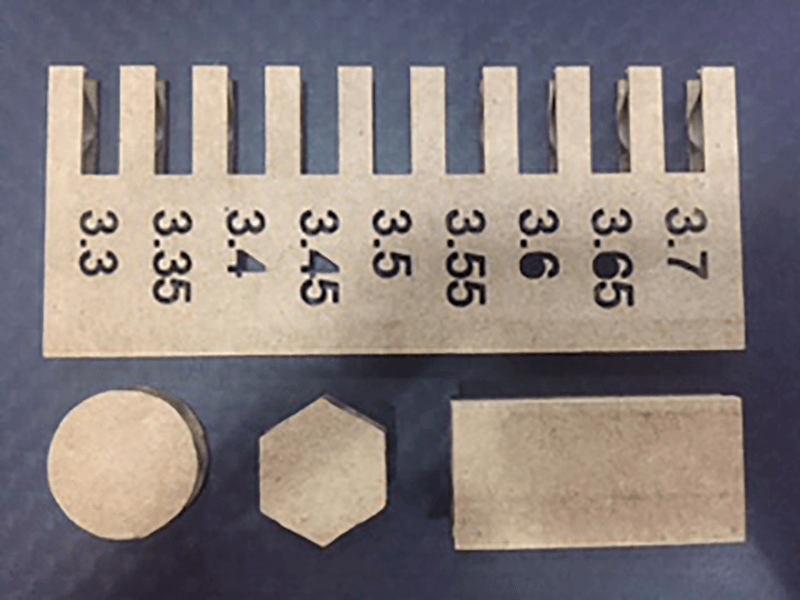
I created a parametric grasshopper file to create the test piece. It is possible to alter the piece for the thickness of material, the range to test and the increments to test between. This will be useful for future projects when I am using different material. The file can be downloaded at the bottom of this page. The material was approximately 3.5mm thick so I did a range of widths ranging from 3.3 to 3.7 at 0.05mm increments.
I also need to take into account the kerf of the laser. Again using card this is quite difficult with the flexibility of the material, but when I move on to ply or acrylic this should be easier.
Having said this I do like the freedom of cardboard as an available and cheap material and also the speed in which iterations can be tried out using both this material and the laser cutter together. In the end I went with 3.4mm for my push fittings. This allowed a tight fit between the pieces so the model did not fall apart.
It was not easy to work out the kerf exactly with this material as it was to flexible to accurately measure using calipers, however I did measure the kerf when I used MDF which can be found at the bottom of this page.
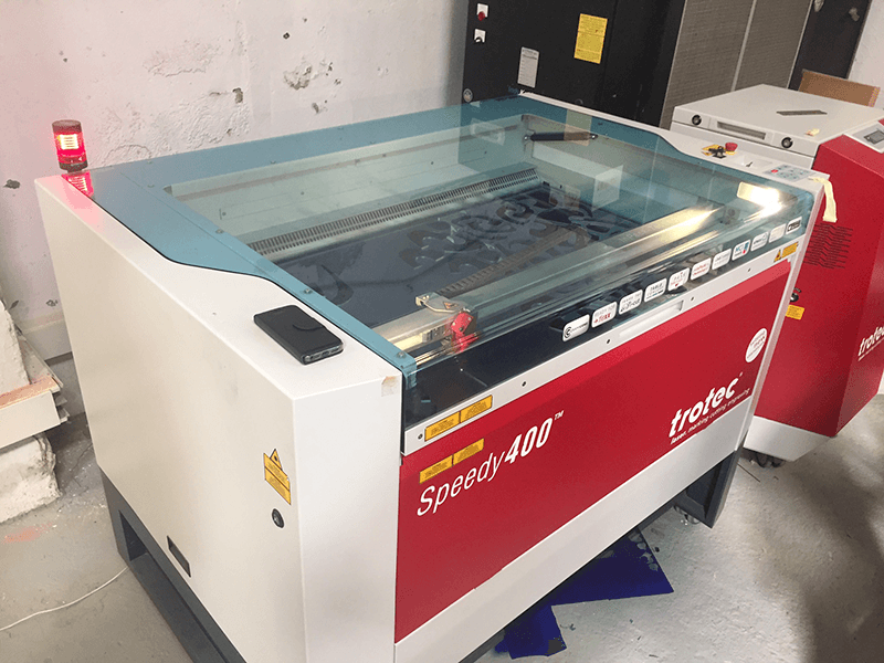
Fortunately the laser cutters we had available all used Rhino and its 'Print' as the interface, so I could use my Rhino files. It was important to ensure the scale and work area of the pieces were set, which could all be done in the Print window by going to 'View and Output Scale' --> 'window' --> 'set'. This allowed us to also set the zero of the laser. We had a few laser cutters available. I used the Trotec and the feeds and speeds for the different machines and materials can be found here.
Even with having the feeds and speeds for the different machines, testing is necessary. This is due to many factors that may cause the laser to be working less than 100%. For instance if the bed isn't level the laser is not always optimally focused. The main reason I found was from a dirty mirror in the machine, this meant the laser was less powerful. This was often due to inappropriate materials or inappropriate settings for the .project which led to a lot of smoke being produced.
After doing a few test cuts I went with:
To cut:
speed - 15%
Power - 100%
To engrave:
speed - 90%
Power - 10%
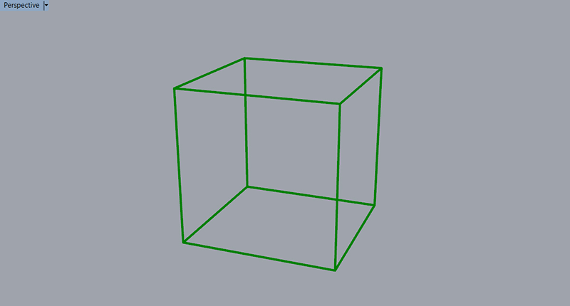
I discovered a geometry while playing around in rhino which ended up being a Cuboctahedron.
Modelling workflow:
I started by drawing a cube and using the explode command to separate out the extrusion into individual surfaces. Next I selected all the surfaces and ran the duplicateborder command to get a square, closed polyline for each surface.
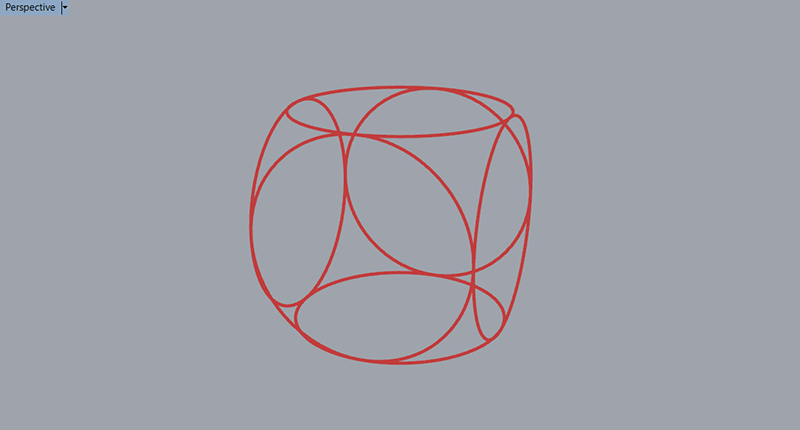
Next I created a circle orientated in different directions using the clickable options in the command line(circle>vertical) and the object snaps, specifically center to draw the circle from the center of each polyline and mid to find the mid-point of each side of the polyline and set the diameter of the circle.
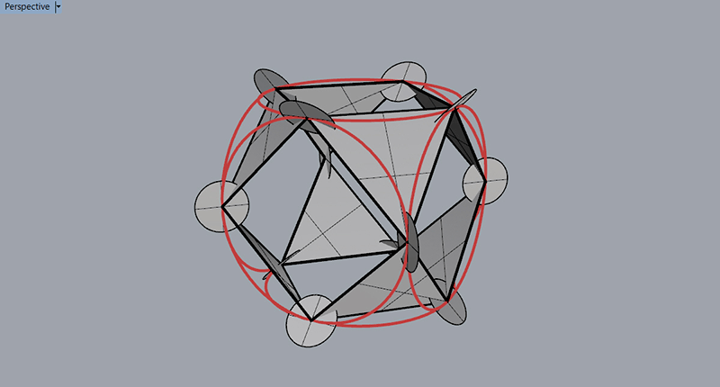
I then joined the intersection of coincident circles to make triangles and drew perpendicular circles to connect them.
Once I had this geometry I was able to work out the angles and create the 2D parts using Grasshopper to make it parametric.
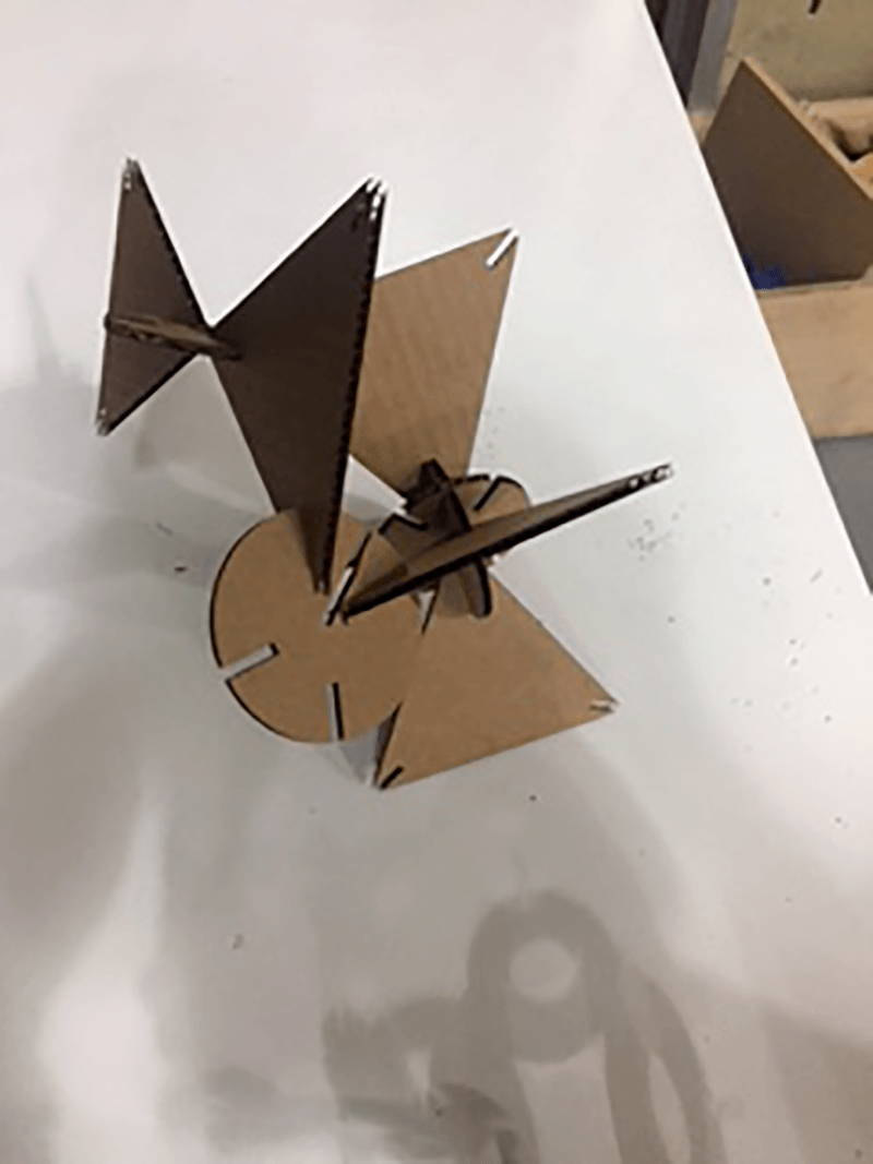
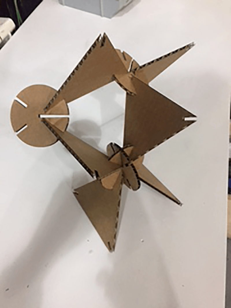
I rushed my first attempt which ended up relatively succesful however there are definitely some improvements to be made:
- increase the size of the push fit gaps.
- add chamfers to the outside corners of the push fit gaps.
- decrease the length of the slots to avoid overlaps.
- decrease the size of the pieces (to create more pieces in one cutting session and waste less material.
- make sure my cutting file fits on the piece to be cut! ('cubo3')
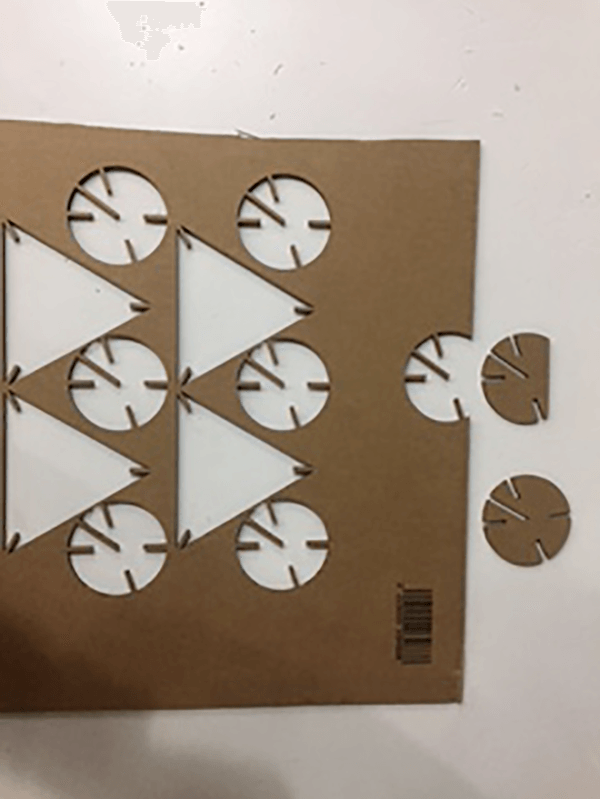
I created a parametric file for the shapes. This allowed me to change the radius of the shapes with the push fit holes altering in size as well. I was also able to change the width of the push fit gaps to match the material thickness. I included fillets on the outside edge of my push fit holes which helps to align and allows entry between the pieces.
I like how this shape fits together and it could make a very interesting modular shelving system. (after a lot of adjustmant) with alternating modules containing different inputs/outputs and all the pieces connecting together and transferring power and information.
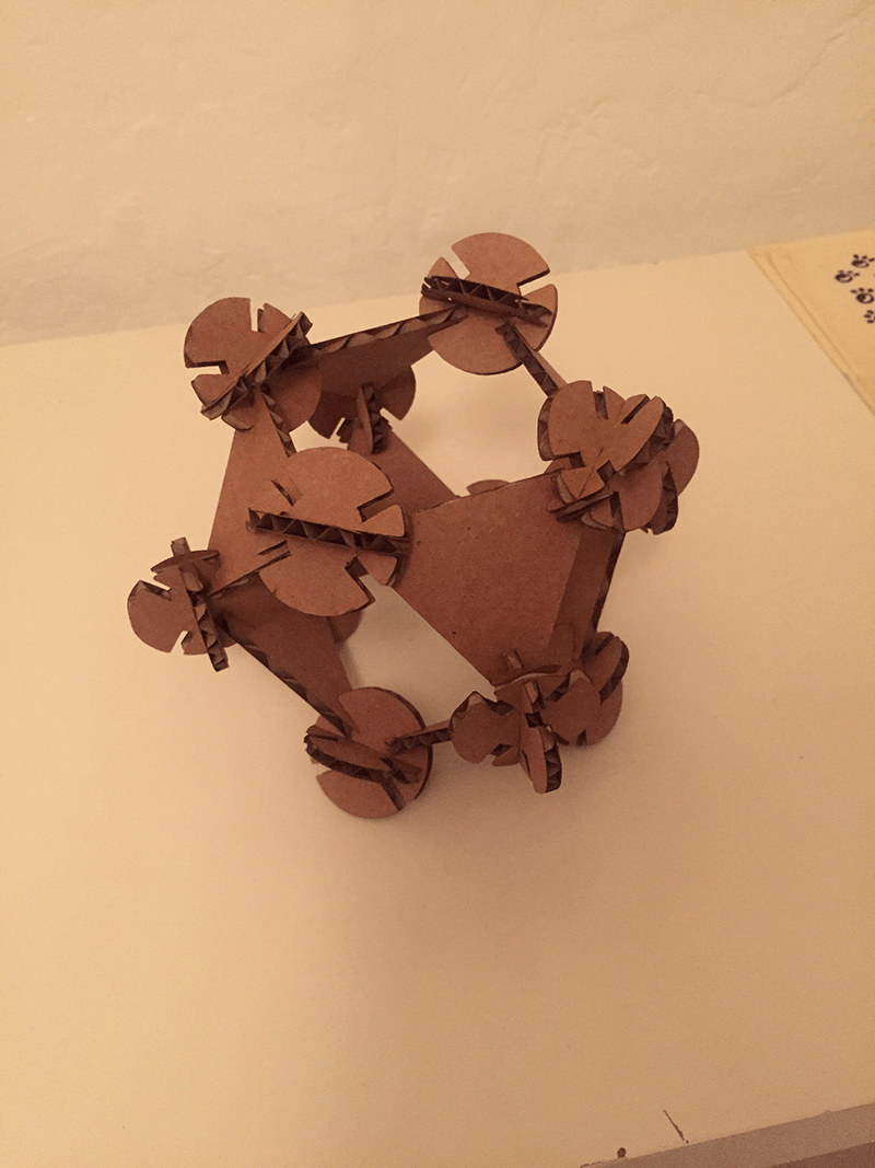
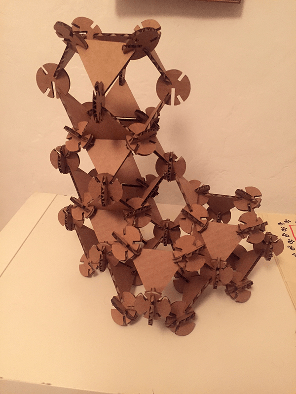
With this card prototype I had a few issues and it was mainly due to the material and the scale. The scale made connecting the pieces fidley and although the logic of my parametric model ensured no overlapping of pieces, it was effectively touching and all a bit cosy. The material was a bit flexible and easily damaged. Although springy and good for push fit, once damaged the joints were not always so good. I would like to play with this geometry further with different materials and scales to see what I can come up with. Also different ways of attachment such as spring fit using wood etc.
Kerfing Around
Having access to the laser cutter I wanted to have a play around with kerfs and how a varying effect of the pattern on a single piece will have a variable effect on the curvature. aka Define the curvature and then apply a pattern so when compressed it forms a specific pattern.
It is amazing to have a piece of rigid material turn into something so flexible and with some patterns even have double curvature.
Some installations and experiments which have inspired me in the past.
- Wooden Waves at Burro Hapold Engineering by Arthur Mamou-Mani
- This Instructable by Aaron Porterfield
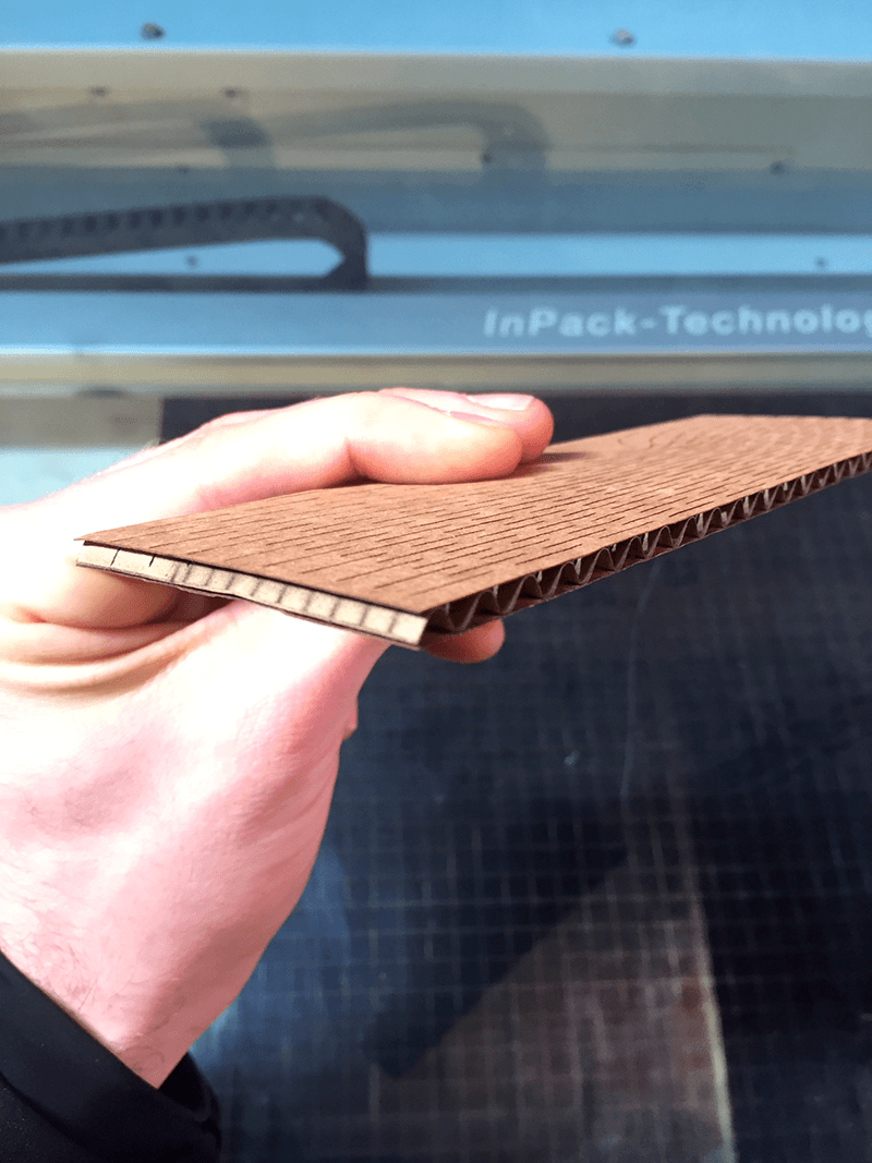
I did some initial experiments using some of the patterns downloaded from the instructable. I was a little disappointed with the flexibility of these experiments, but then realised I did not take into account the direction of the corrugations. A colleague did similar patterns in card across the direction of the card with much better results.
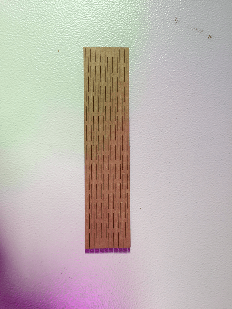
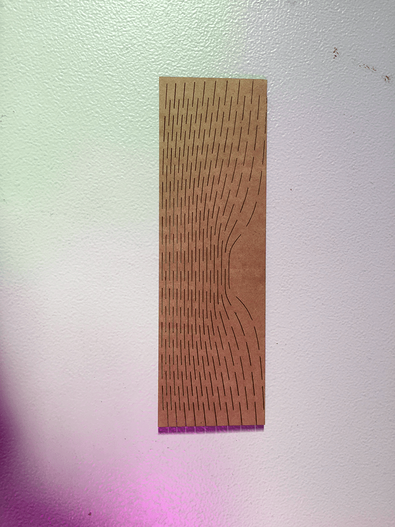
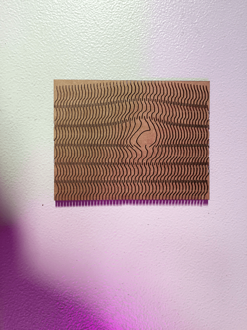
I played around with the orientation with the pattern in grasshopper using attractor points. I did a small test on a thin (~2mm) piece of ply with interesting results. Of course I had to test the flexibility/rigidity hence the two separate parts
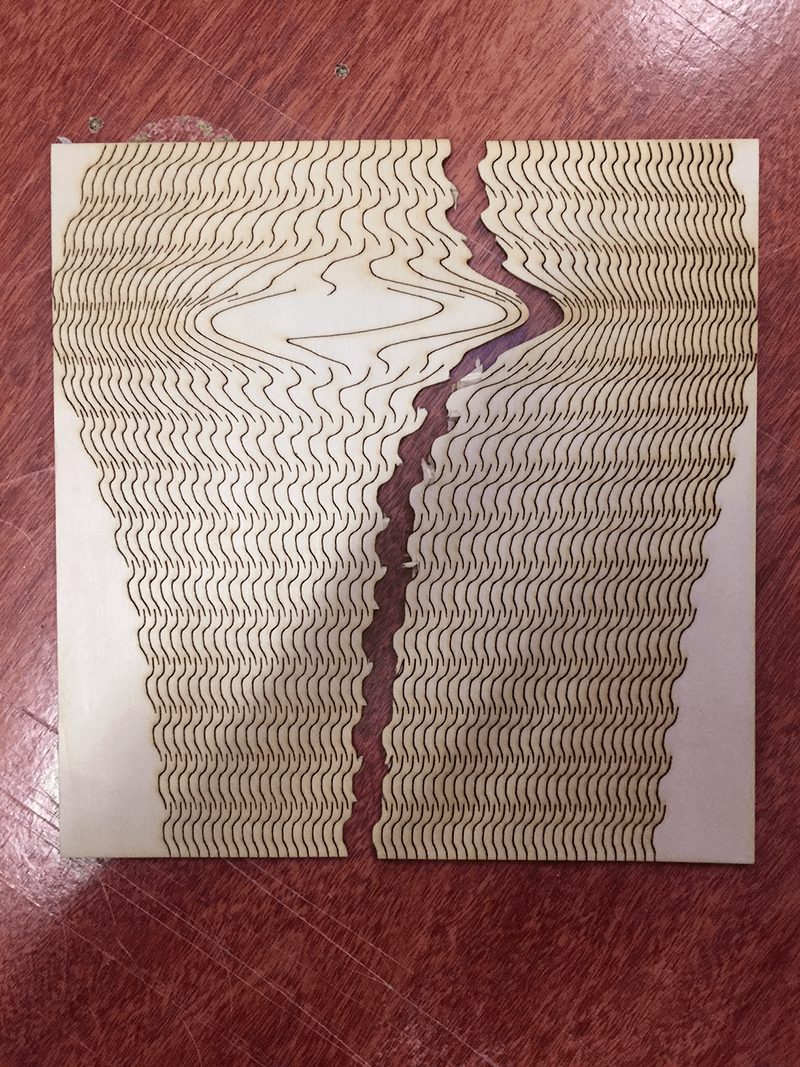
I did find that the curvature did change and I want to have a play with the pattern further. I would perhaps do various, more linear but different spaced patterns and measure the maximum radius. Then in grasshopper I could create a surface, analyse the radius at specific points and apply the pattern density to achieve this.
Further experiments - kerf cardboard (take off just half of material - vary width of hole). raster on cardboard. kerf to allow angular bending (3d bending)
Vinyl Cutter
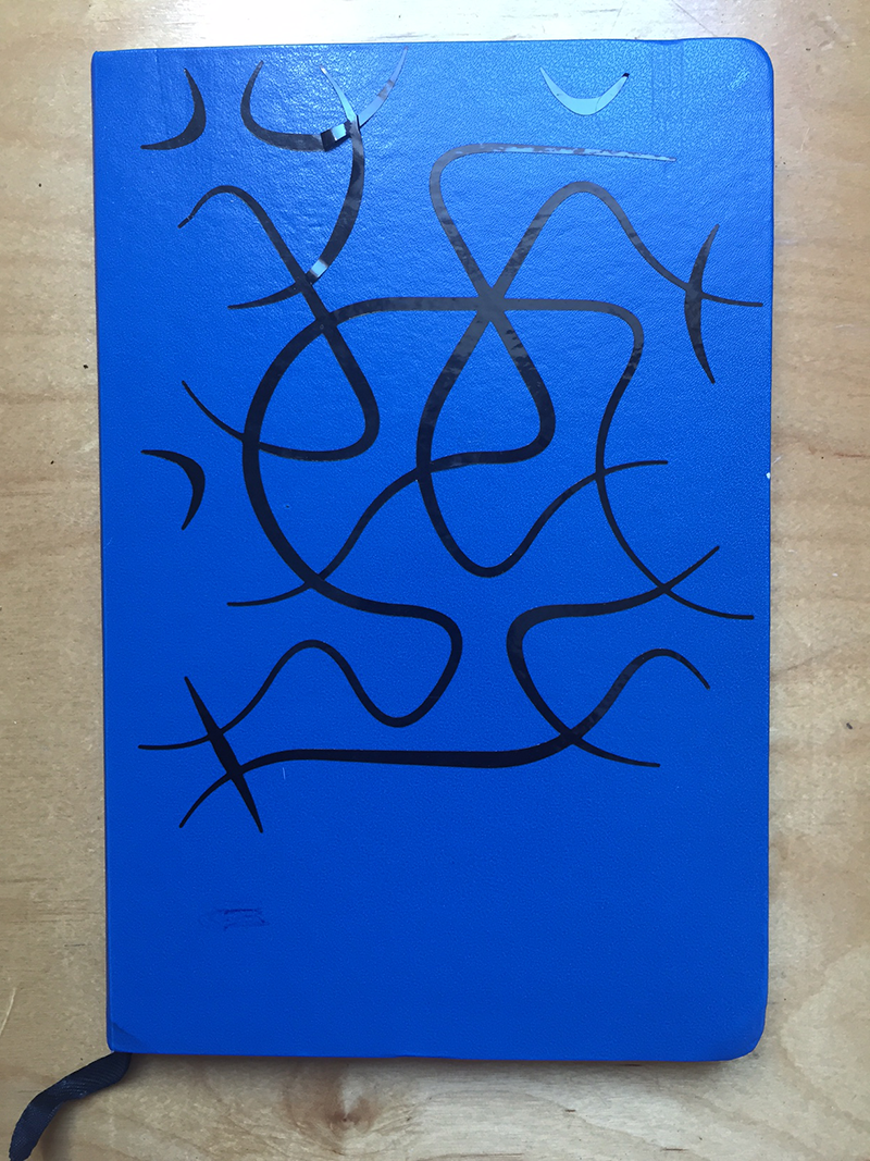
Using Grasshopper, I created a file that connected each of the 2 sides of a hexagon. As hexagons are infinitely tileable this creates a series of curves that creates a pattern with non having 'loose ends' except for the edges. A bit of randomness included as well as some variable pipe and I ended up with this pattern. I took the curves and saved them as DXF file types so they could be read by the vinyl cutter.
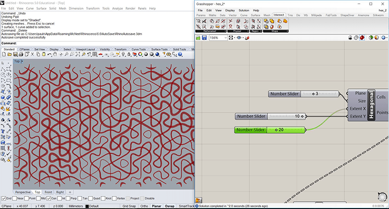
I initially scaled it to fit on my computer, but after seeing colleagues attempts with small intricate designs I scaled it up slightly to fit on my Spanish workbook.
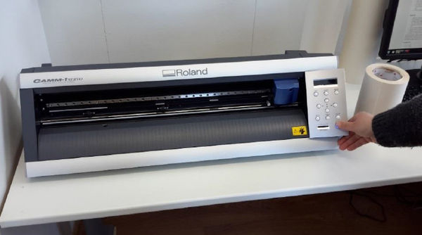
We used the Roland GX-24 vinyl cutter for this which is a remarkably effective machine.
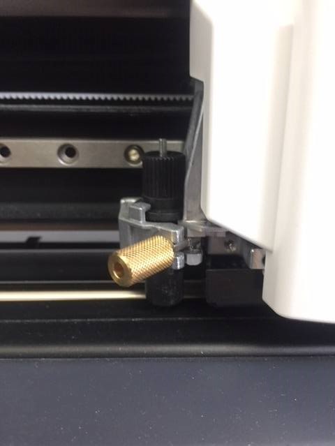
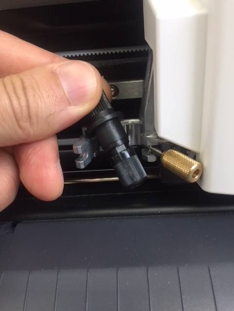
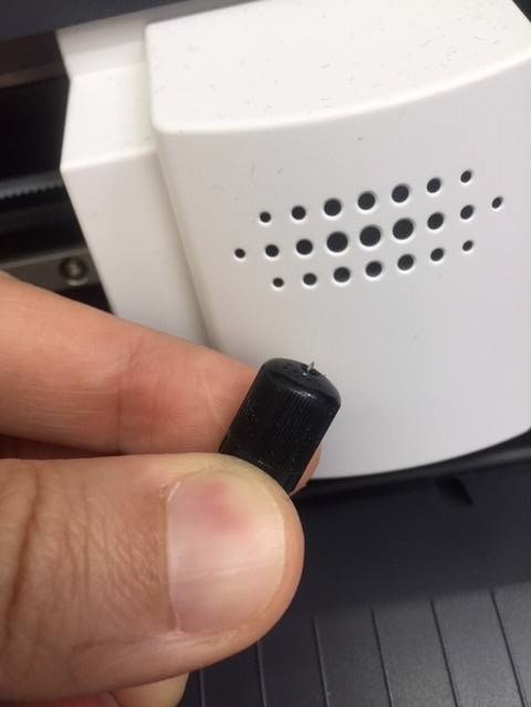
Initially we need to set up the blade of the machine. We do this my twisting the brass nut and removing the blade housing. By turning anticlockwise we can loosen the grip on the blade and re-tighten so the blade is just poking out. It is interesting to see the blade sits in a small bearing which allows the blade to rotate as it cuts the design.
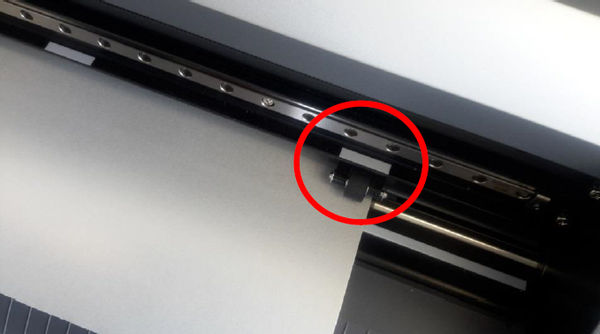
We used sticky backed vinyl for the material and the machine can take either a piece of material or a roll. Once we align the rollers and lock in the material we tell the machine which size vinyl it has and it will calculate the size if it is a 'piece'.
It is possible to print directly from illustrator which is useful as I can easily export as .dxf from Rhino. From here we go to 'print', get the material size from the Roland machine if it is a piece and cut. Setup for the machine can be found on our Roland group page.
Once cut we remove the bits we don't want and apply blue backing paper to lift the design of the initial backing. I can then transfer the design onto my book.
I definitely still struggled with this design, with bits not coming off easily. My Spanish workbook had a slightly glossy finish. This made it hard for the design to stick down and so remove the blue backing. I managed in the end, but in future I will make sure I use a better surface.
2018
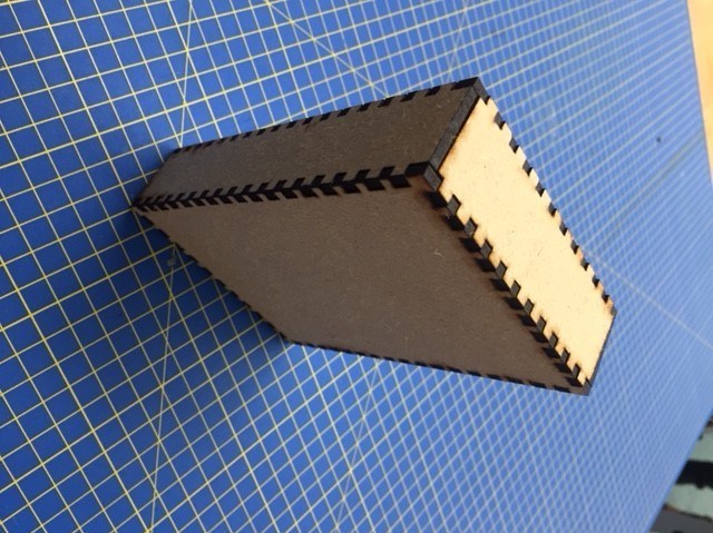
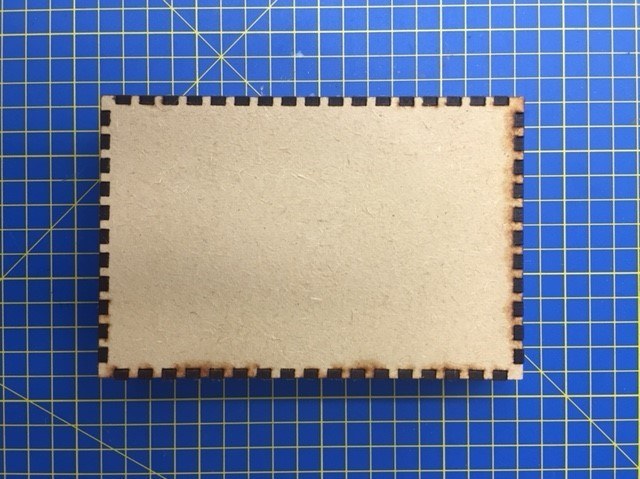
Continuing on from last years project, I created a parametric box with tabs. The file can be downloaded at the bottom of this page with explanations within the grasshopper definition. I am going to use mdf this year; this material is much more rigid so it will be easier to find values for my machine such as the laser kerf.
In Brighton FabLab, we are lucky enough to have a shiny new Epilog Laser (Helix). This meant nice clean mirrors, a level bed and a super efficient extraction system. Our tutor, Luiz suggested putting down a sheet of thin aluminium to protect the honeycomb bed underneath. When you actually have something to clean it is amazing to see how much dirt comes of just a single cut, especially with the glue from MDF.
Doing some test we found that 25% speed, 100% power and 600Hz allowed us to cut through the MDF. Further settings and details about the printer can be found on the labs shared docs for our Epilog laser. For engraving I used 75% speed, 100% power and 600Hz.
First, to find the laser kerf, I cut several squares of known dimension and then measured the widths at several locations using verniers. I took the average of all the differences to what was expected and found the laser kerf of the Eplilog for 3.5mm MDF using the settings above to be approximately 0.136mm for one cut laser. So my practical kerf distance would be half of this - 0.68mm.
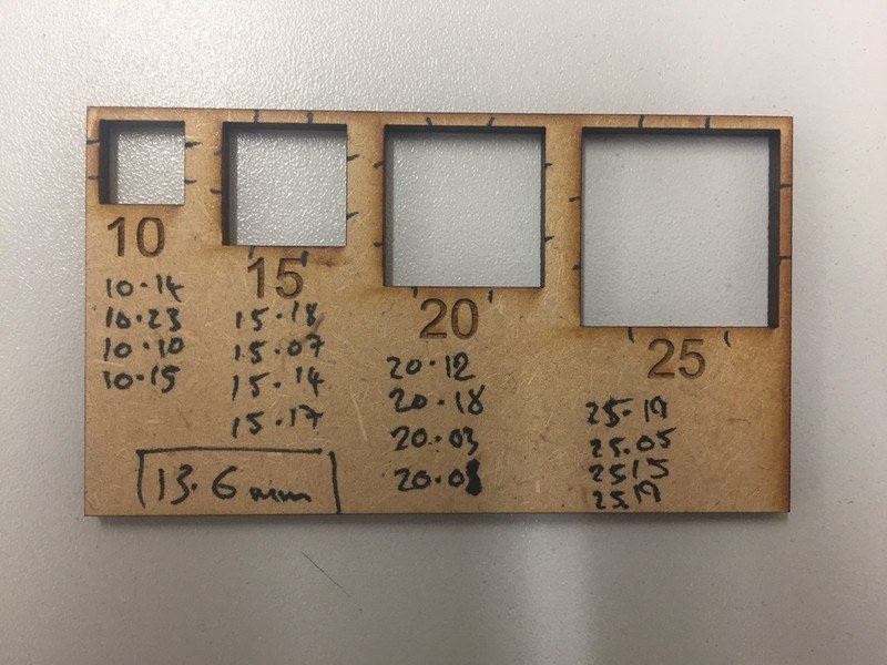
Next I used my grasshopper definition from 2017 wich creates a test piece of different widths. I offset the piece by the laser kerf value and found which offset had the best fit. The 3.2mm was a tight fit. If I was creating a model like I had before
I initially misunderstood what I needed to create my box using my grasshopper definition. After some testing, I realised all I needed to know was my material thickness and the laser kerf. I offset the my tabs on each side of the joints by 0.13mm (the laser kerf) and this was a very cosy fit. (in practice I ended up doing 0.1mm either side) I now have a box for my current projects.