Week 8 - Computer-Controlled Machining
Group assignment
test runout, alignment, speeds, feeds, and toolpaths for your machine.
Here is a link to our lab's page which includes links to all our group assignments.
Assignment summary
what I achieved/learned this week:
- finished my full kitchen helper Grasshopper model and embedded it into my website
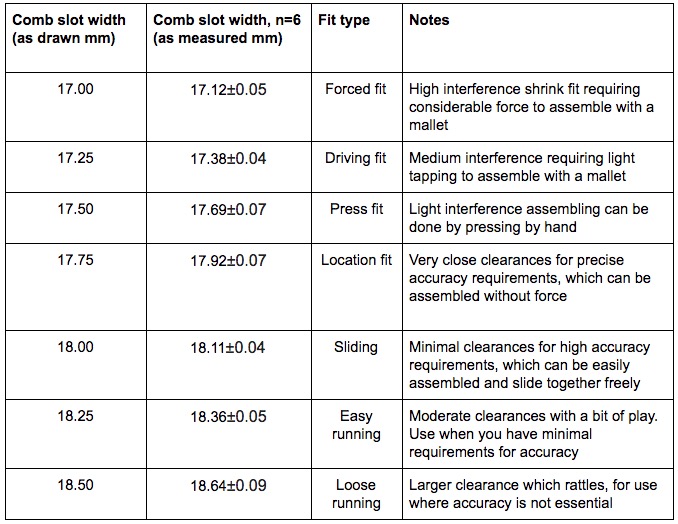
- created the test combe for our group assignment and did measured the dimensions of the different fit types
- created a full test assembly in Solidworks for my kitchen helper model using 3 components (approx. 500 mm length)
- CNC machiened the components using the AXYZ CNC milling machine
- assembled my project with a mallet and checked it against the original design for size.
Individual assignment
task: make something big
Originally I was hoping to drive my complete kitchen helper from Grasshopper. Here was my first attempt at the full parametric web-based model. It is very basic, with no consideration for joints, tolerances, or making it desirable. But it worked as a full parametric design, and I learned grasshopper in doing so, so I'm actually very happy about this. I started it in week 3 (CAD week), and then picked up up again recently.
here is the .gh grasshopper definition file to download
I've parked that, and decided to make it in Solidworks. I will also try to make it using Design Tables in Solidworks, where the design can be driven using an excel spreadsheet. But for now, I want to build the model up in stages, using the spiral development. Here are a few test pieces that I wanted to do first to test the various types of joints in my kitchen helper. I designed them to have a very tight tolerance, with 17mm slot spacing for the 18mm wide ply based on the test comb that I designed for the group assignment.
Here is the link to our group assignments page.
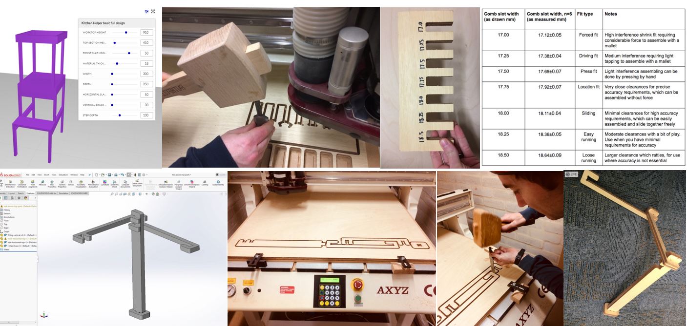
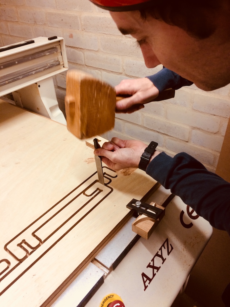
So here I am hammering out the tabs with a chisel and mallet.
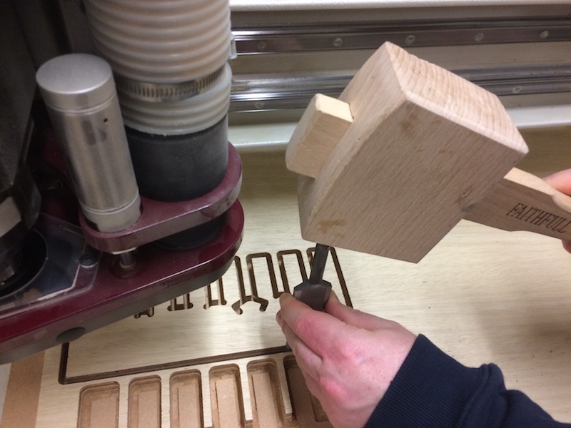
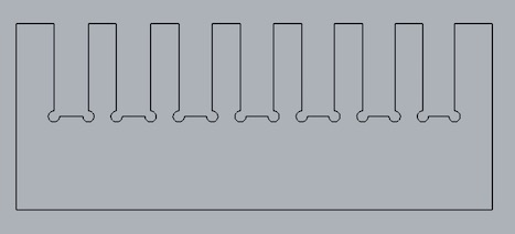
And here is the comb ready to be tested with the "as drawn" values.
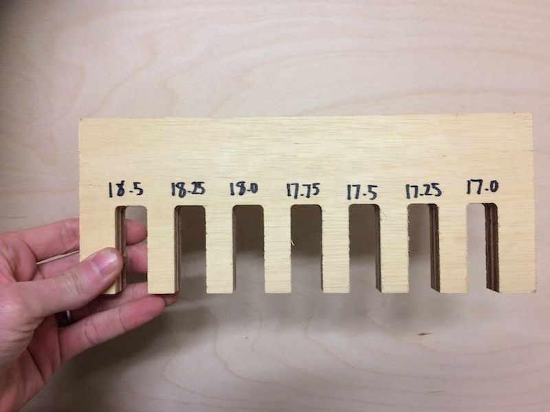
And here is the comb being tested for the type of press fit.
And here are the result for the types of press fit...I do need to measure the actual slot widths and put them into the table too...
here is the original Rhinoceros file of the CNC comb to download
here is the DXF file of the CNC comb to download
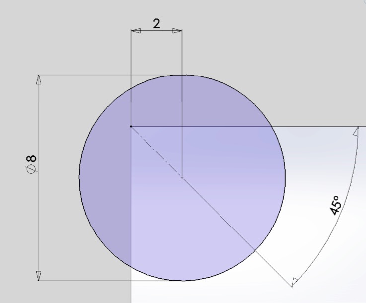
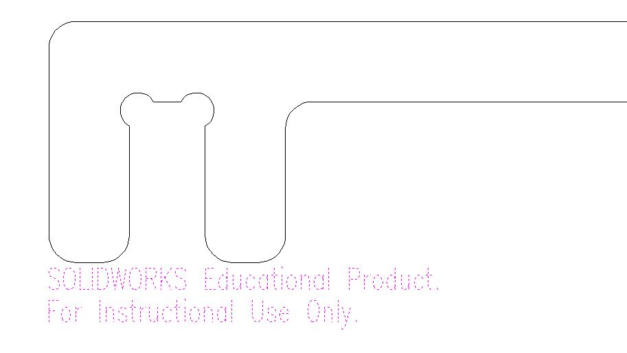
Originally, I messed up the T-bone joint by simply putting the circular hole right on the corner with the same diameter as the cutting tool itself.
Of course the cutting tool couldn't then get round the corner of each joint, so I needed to open up the joint with an 8mm hole that was inset at 45 degrees from the corner of the slot by 2mm (horizontally or vertically) as shown here. I used this throughout for all my joints.
I created a simple test model which will represent the types of joints I will use in my model. Firstly, it's a good way to test out the types of fit to see if there is enough friction in each type of joint for it to be sufficient for a genuine press fit construction kit - i.e. where no screws or glue will be needed for the final model. Secondly, it's a great way to check out other design features, like the wall thickness for stiffness, the proportions for bending stiffness, and the joints themselves for lateral stiffness (i.e. parallelogramism!).
So here's the original test model design I did in Solidworks.
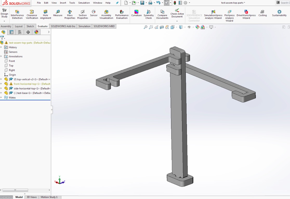
here are the Solidworks part/assembly files to download
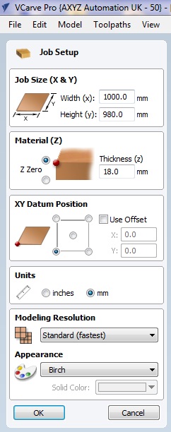
So then we took the .dxf files into VCarvePro, and went to the job setup with a width of 1000mm (maximum taking us right up to the edges) and height of 980mm (which includes the 20mm we've taken off for the clamps at the front of the bed). Note the Z zero is on top of the work surface, while the XY Datum position on the front left corner of the work surface.
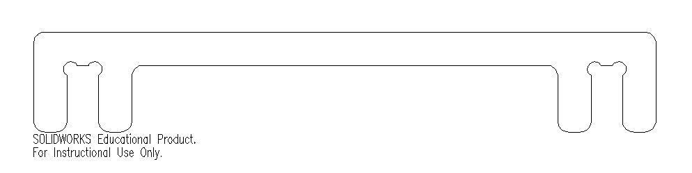
We then have the .dxf file brought in.
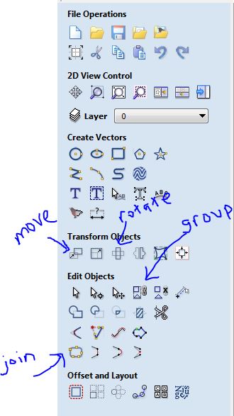
and you can drag the left mouse button over the drawing to select everything, then double click this to move it around.
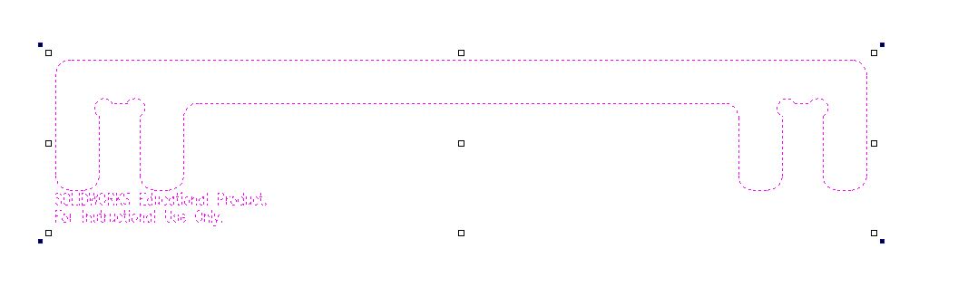
Then we have our outline, but the lines are typically not joined, and if using the educational version of solidworks, there is the watermark that we need to remove which can be done by dragging over it (carefully so as not to select any of the rest of the drawing), then hit delete.
You can then move, rotate, join (touchling lines) and group (not touching lines).
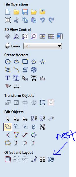
Then with multiple drawings you can nest these automatically. With my drawings this worked really well to line the parts up along the bottom of the piece to minimise wastage.
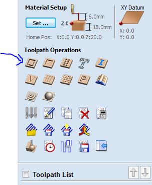
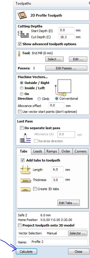
Then to define the profile toolpath...
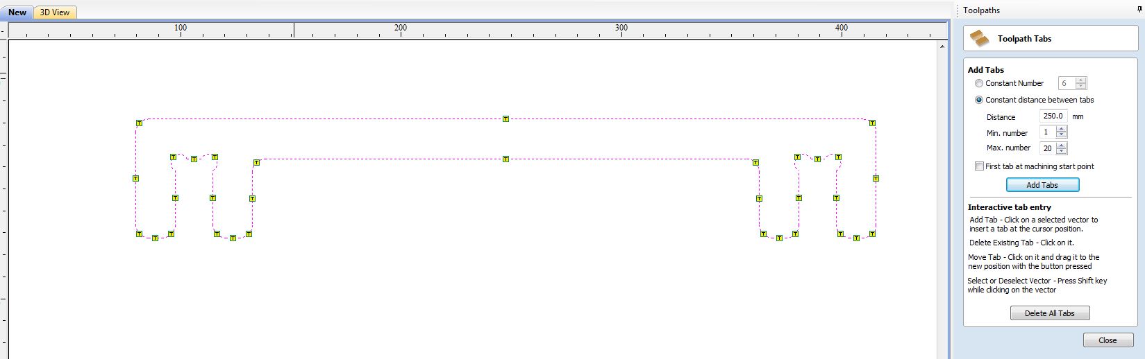
Then you need to drag over the entire drawing to select everyting, and check the Add tabs to toolpath box, then Edit tabs.

You'll then see some tabs automatically generated on your drawings, but you can drag each tab to move it around, and you can select on the lines to add extra tabs. It's good to get a good coverage of tabs all round, and for adjacent parts have tabs that line up next to each other to tie the parts together afterwards.
Then to calculate the tool path.
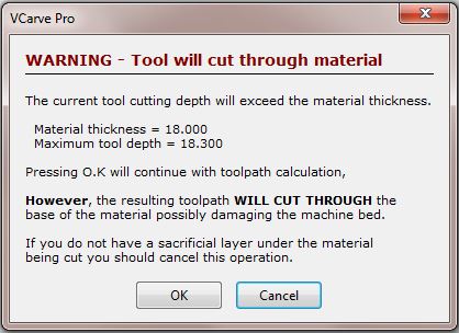
And a warning sign to show that you'll actully be milling below workpiece.
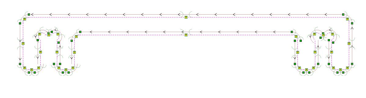
Here's an example of the toolpath showing where the tool will be cutting (hopefully outside your work!)
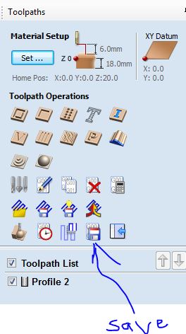
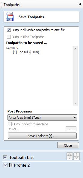
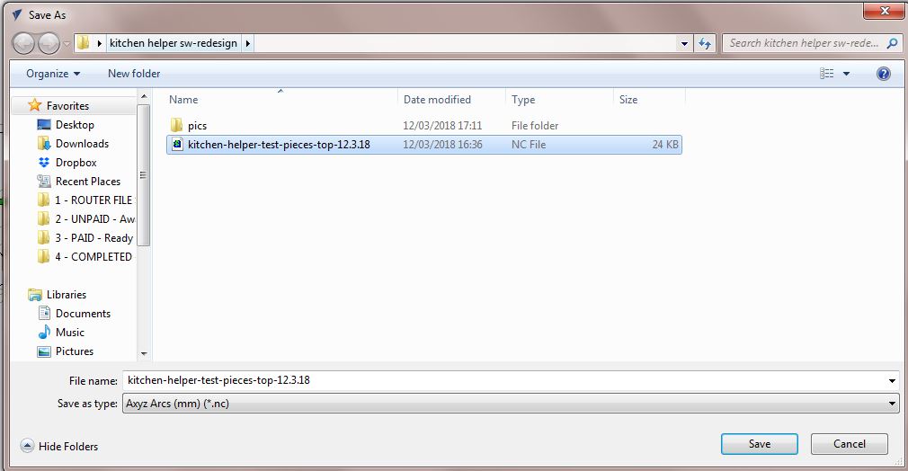
Then to save the .nc file with all visible toolpaths in one file.
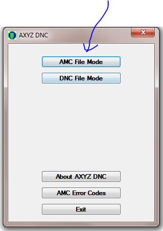
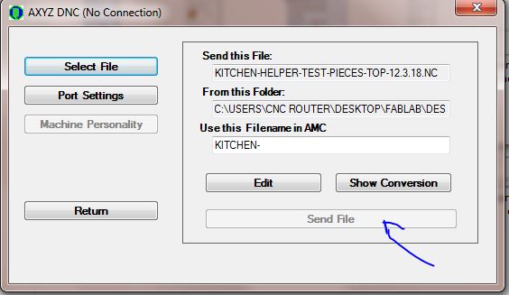
then to open the AXYZ software which will send the .nc file to the cutter.
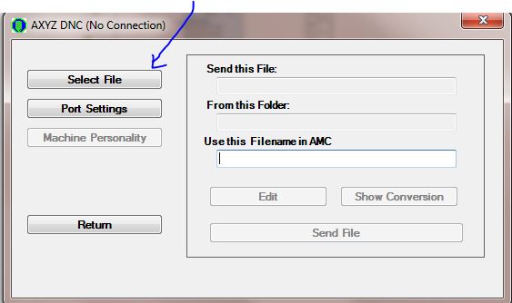
Select your .nc file...
Then send file to the cutter! then you'll need to turn on the extraction (in our case as the vacuum isn't working at the moment) and then find the job, press enter, and enter again to start.
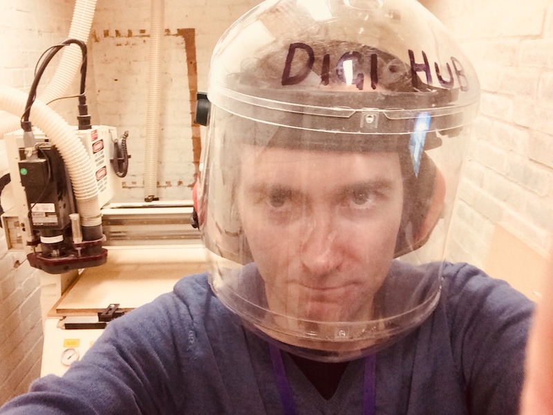
of course then keep an eye on what's happening, ready with the emergency stop just in case, and wearing face mask, ear defenders and closed leather shoes of course.
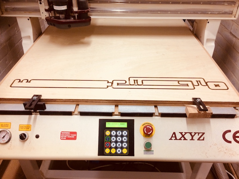
and here's the test parts cut and ready to be removed.
using a chisel and mallet to remove the tabs was very satisfying.
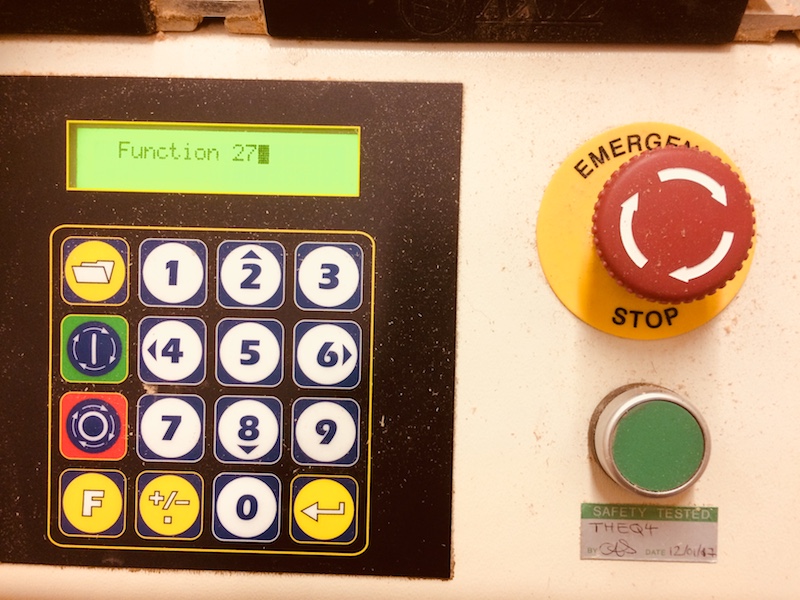
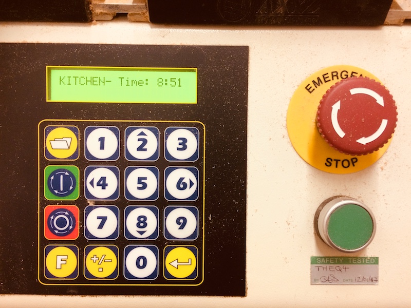
Pressing F and 27 and enter to show the actual milling time (so the job can be costed). In my case the job took only 8mins 51 seconds. Andrew's table took 39 minutes for comparison.
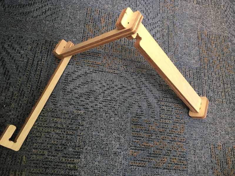
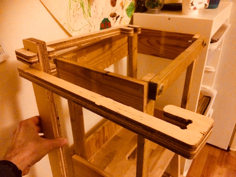
Here are the four test pieces assembled and married up to the existing kitchen helper design. Overall the test for all 4 types of joints was a success. Now to roll this out to the rest of the design and make the whole thing. So far, I've not made something massive, but have made something big.
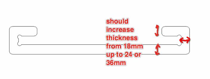
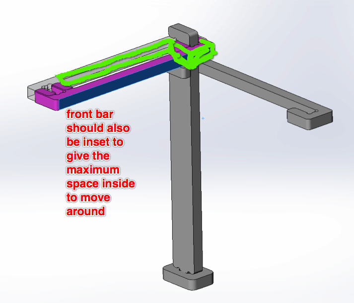
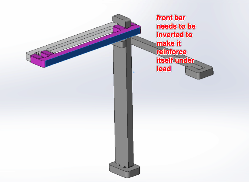
Well this seemed to work very nicely with a simple press fit forumula of slot_width=lug_width-1mm, where the lugs were simply 1mm longer/wider than the slots. A few other things I learned though, was that I should invert the front bar so that when leaned on, it will reinforce the joint (not loosen it), and that the bar thickness should be increased to increase bending stiffness - doubling it should do nicely.
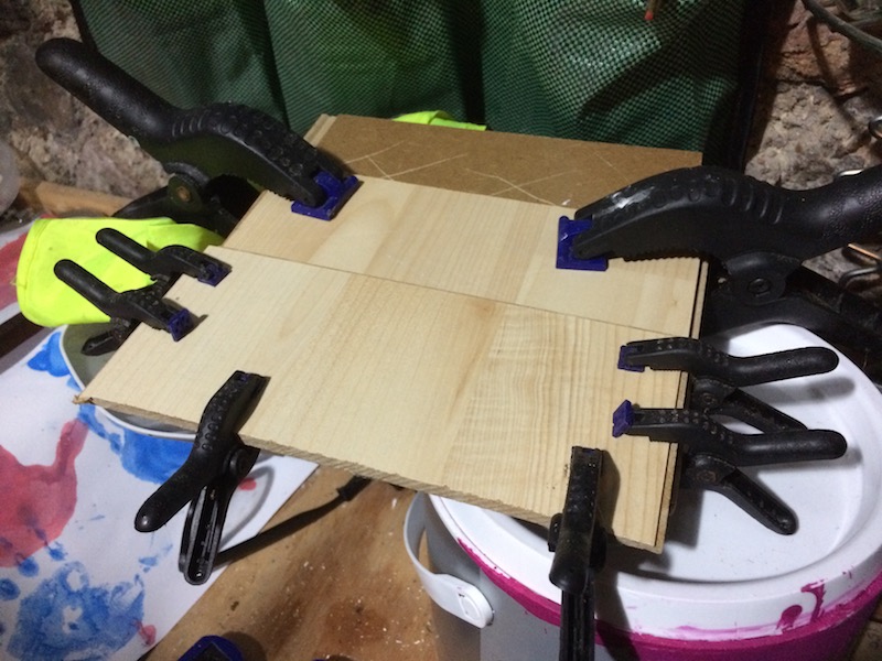
Now I am seriously considering taking this further and making this out of 3 x layers of 6mm floorboards that I ripped up from my spare room a few weeks ago. We've been playing around with laminating these together recently, and I think it will make a great material as we can get a nice veneer on both surfaces of the ply, and it is very strong indeed.
Here's Chris's door sign, CNC milled to show his skills, I love it! Definately and idea for the future...
My notes: Japanese joinery...amazing! check out the kamakura fablab thiniverse 'japanese joinery' Toolpaths - Kerf is the material removed. Runout - diamter of cut is larger than diameter of tool. Trochoidal milling we will be able to use 1000x1220x18 mm (x2 sheets). We can use ply, birch ply, or MDF. We have 6 mm end-mill, not ball-nose. Bear in mind the offset, can be up to 1 mm for our cutter (e.g. 7 mm diameter cut in this case, but typically more like 6.5 mm) climbing (finishing cut) vs conventional cutting (rough cut) There are three types of T-bones to cut, and if you design it correctly you can design a fastening pin/clip to get the parts to hold themselves together without adhesives. Note that in order to machine we need to design the 2D drawing (.dxf) including the T-bone, but the software used to drive the milling machine can generate the 'tabs' or 'bridges' to keep internal parts joined to external parts that can then be cut off at a later stage.