Week 6 - Printing and scanning
Assignment tasks for this week
Individual assignments: design and 3D print an object (small, few cm) that could not be made subtractively + 3D scan an object (and optionally print it).
Group assignment
test the design rules for your 3D printer(s).
Here is a link to our lab's page which includes links to all our group assignments.
Assignment summary

what I achieved/learned this week:
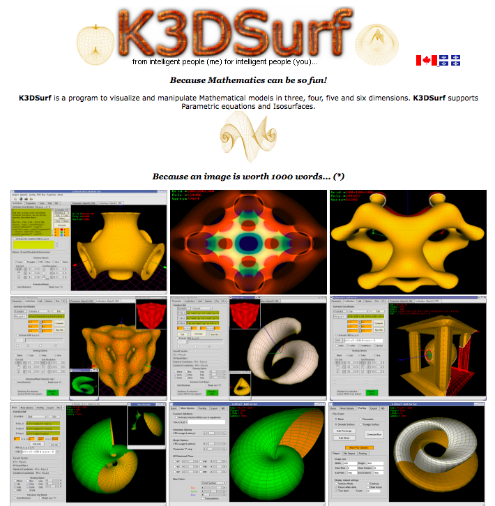
- experimenting with mathematical K3D Surf and Structure Synth software to generate interesting 3D mathematical structures
- use K3D surf to generate a small part and 3D printed it on the makerbot replicator 2X
- tested the design rules and capabilities for our new creality 3D printer
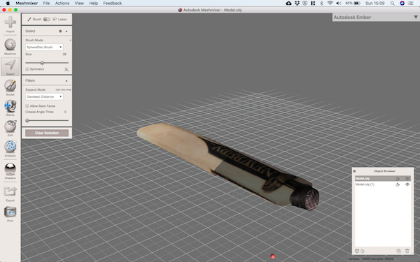
- scanned a cricket bat in two stages using our laser scanner and fixed the pieces in meshmixer
Individual assignment: 3D printing
3D printing is great for creating complex geometries quite quickly. It's not the solution for everything, but can be very handy in particular for small components needed in the prototyping stage. The process involves creating a CAD model, then exporting this as an .stl file. Then you load the .stl file into the machine software, orient and specify printing parameters (if you want support material, layer thickess etc), and then print the part.
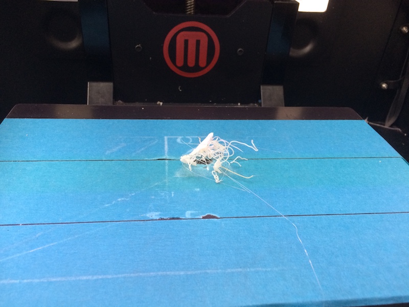
I wanted to print something geometric and interesting and had a few ideas in mind. Firstly, I went with something that was perhaps a little ambitious for the Makerbot Replicator 2X (without support material). I think the walls were a bit too thin for a small model (about 50mm overall height). I could have printed it larger, but I didn't have much time this day so I changed tact and did up a different model, more solid, more robust, but actually more interesting in the end. Here's the first design:
Then here's out it came out...she's a beauty!
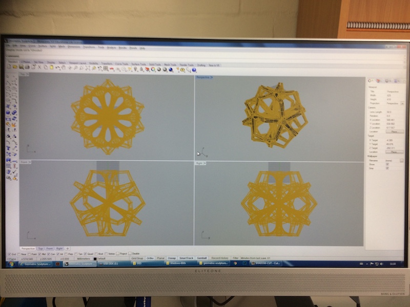
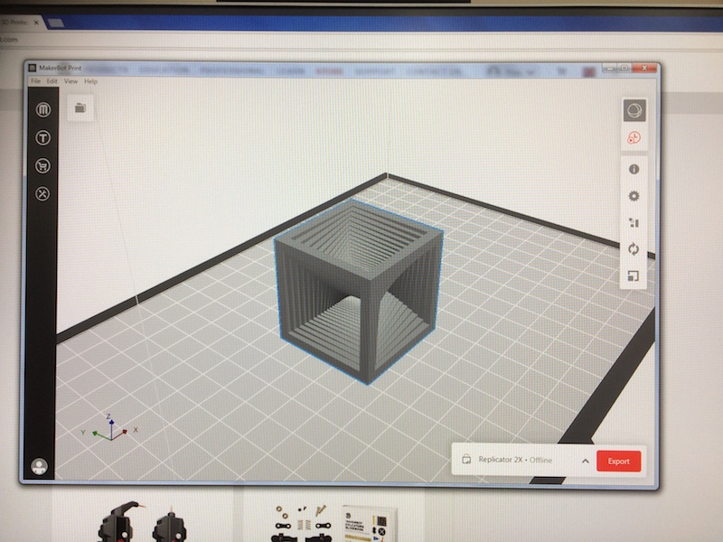
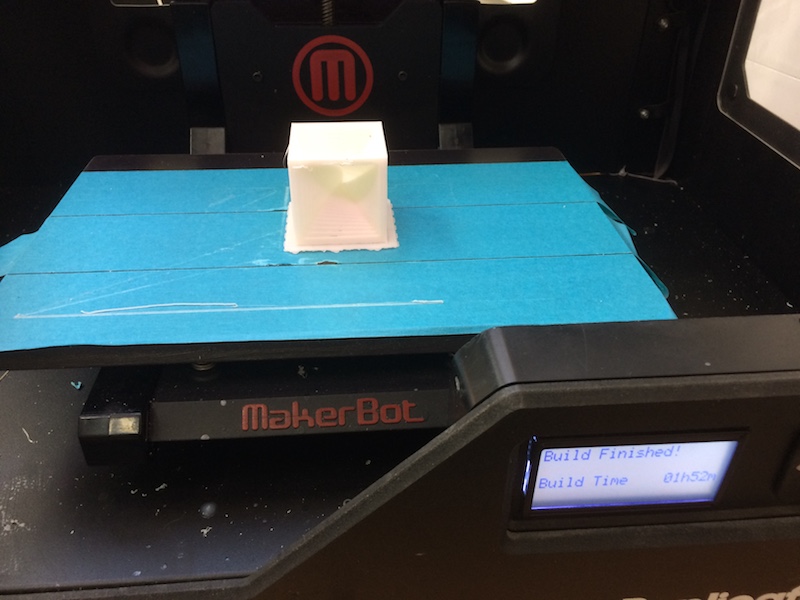
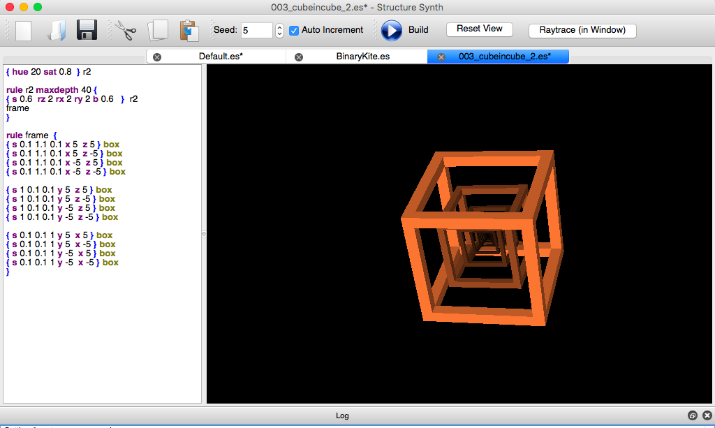
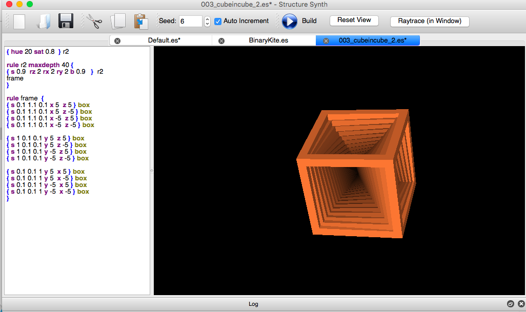
And here's the 2nd attempt, with a more suitable model. I used the new version of Makerware software, but the interface is not as good (I think) on this new model. I prefer the older version where by default you get straight in there with all the settings for layer thickness, build plate temperature, nozzle temperature, raft size etc. Anyways, it's very easy to generate the .x3g file which has all the G-Code, it's simply a case of specifying which nozzle (the default is the right nozzle to which our spool was connected), then press export. I was quite surprised that without any tweaking, this one came out without needing any support material, since the step size is relatively small between each layer so that was ideal. The model itself I downloaded from grabcad. It was created by jp_math who used Structure Synth, which is used to generate 3D structures by specifying a design grammar and looks really cool. My plan is to have a play with Structure Synth and possibly recreate this and make it parametric in Grasshopper. It would also be possible in Solidworks, Fusion, Rhinoceros I'm sure, but think it will be most useful in Grasshopper as I want to do this kind of form for any polygon, not just a square. The design itself I found really interesting. I wanted a very mathematical geometric form. I really like the gyroids and other isosurfaces that are possible with K3Dsurf. Here are some examples from there and from Structure Synth too.
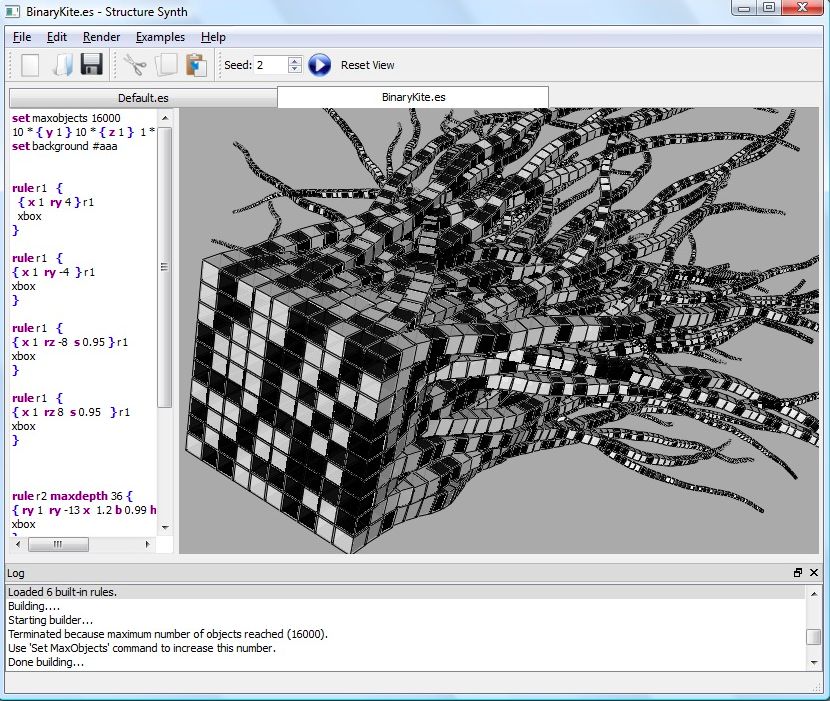
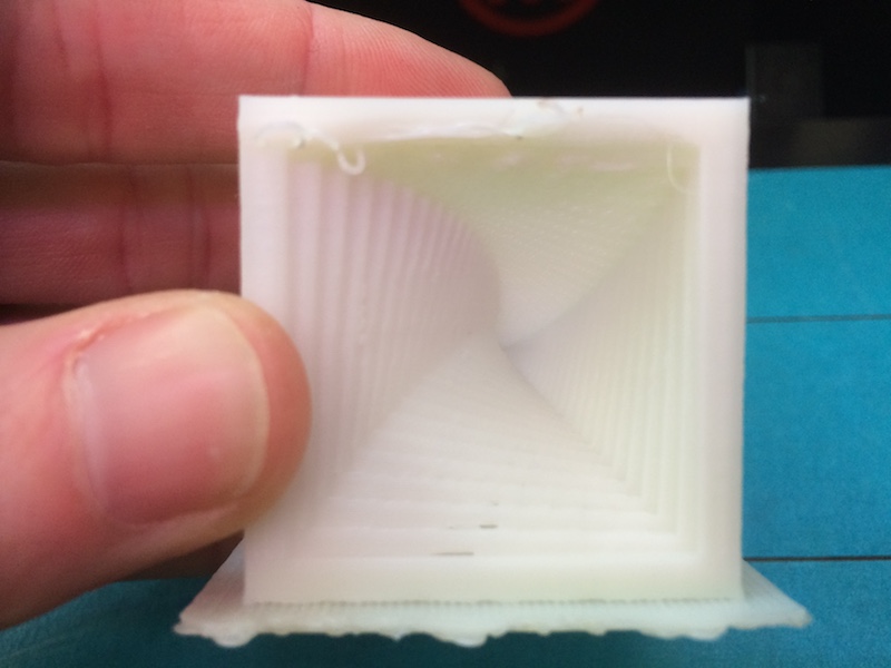
In this case of my print for this week, it's a simple set of thin-walled squares which rotate about about both X and Y as they sweep upwards. There is a repeating pattern, with each of the 6 faces the starting point for the geometric pattern. Here's the cube in cube example loaded into the software.
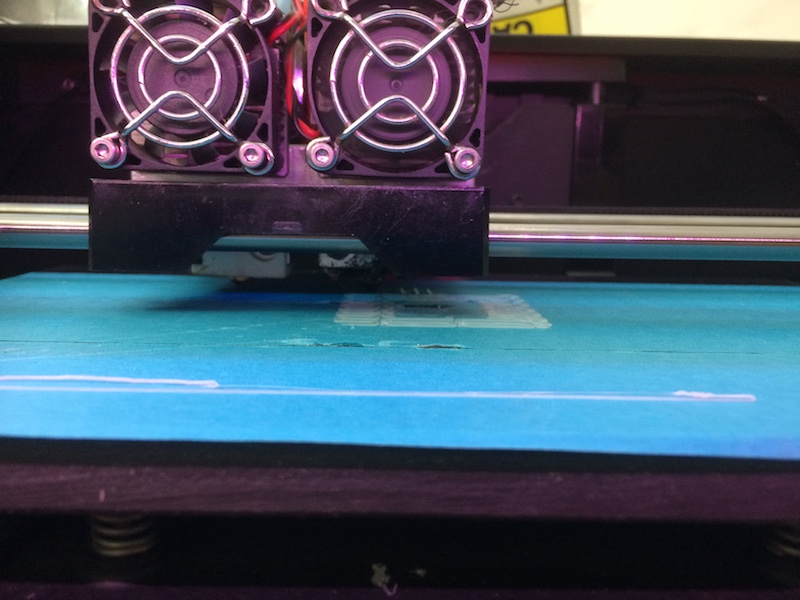
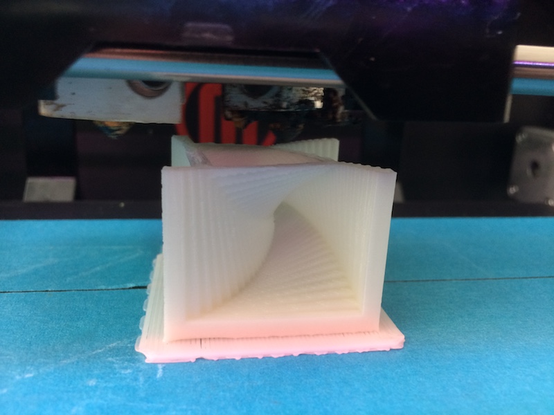
what followed was a reasonably successful print. Here are a few images of it printing along the way. Fingernails definately got some punishment in this 90 minutes.
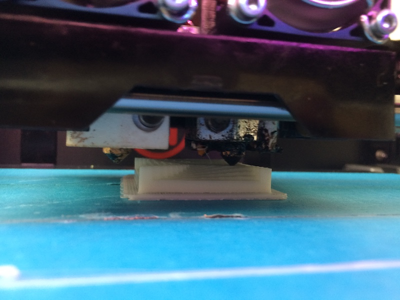
and the final product, with only a few blemishes on the final layers where it seemed to struggle to bind the fill with the shells on the outside.
cube-in-cube.stl file to download
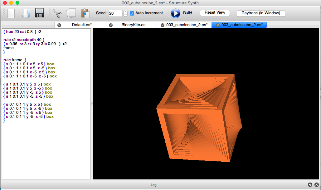
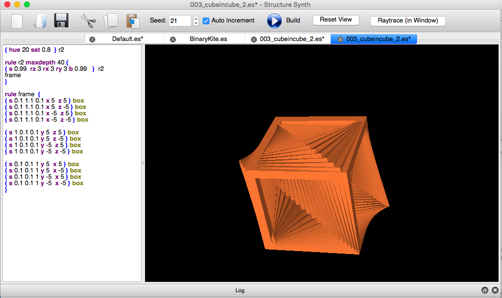
So then I did some playing around in structure synth, and here are a few of my first models
we've been doing quite a bit of printing with out students, and on our local site here we produced some introductory documentation to help students understand the basics of 3DP and to know where to go to get things done. Here's the documentation, apologies for the image quality - I had to export it all as a jpg.
Makerbot Replicator 2X We also have makerbots available to print work in the Advanced Engineering Centre. Here are the instructions and design guides which we hope are useful. Designing Parts to be Printed on the MakerBot Replicator 2X SavingSize
- Please save your file, as your name, what the part is called and the approximate size, colour and material i.e. Joe_bloggs_castle_50x50x40_blue_abs.stl
- Save your files as STL using (fine setting) in Solidworks, Rhino or equivelent and reload the STL file to check the curves are smooth enough.
- Save each item as a separate STL file
Things to Avoid
- The maximum size is 220mm long x 140mm deep x 140mm high
- Bigger is not always better, only make it as big as it needs to be
- The extruders are typically 0.4mm wide. 0.4mm will give a single wall, 0.6 – 0.75 will give 2 walls that are merged. 1.25 is good for 3 merged walls. 1.5mm for 4 walls
Tips
- Do not print out pieces that could be easily be made by hand or with another machine e.g. laser cutter Very thin or small items will not print
- Long flat strips are hard to make as they tend to warp.
- Avoid unnecessary protrusions, especially on the base of the part.
- Avoid overhangs that will need support material. The Makerbots can handle up to 68 degrees from the vertical without support (normally).
Layers
- Cutting models up and adding locating holes can eliminate a lot, if not all support material.
>- Make wall thickness as small as possible that the design will allow, but no less than 1mm.
- When designing your part think in what orientation it will be printed and the supports that it will need.
- Where supports are, think if you can include it in the model, then there will be less post processing removing supports, giving a better looking model.
There is a weakness between layers
HolesParts that fit together
- Model holes bigger than they need to be to allow for shrinkage.
- Holes smaller than 10mm diameter should be have a clearance of 0.4mm e.g. for an 8mm hole make it 8.4mm
For holes larger than 10mm, increase the clearance- 1mm clearance for 50mm holes i.e. 51mm
- 2mm clearance for 130mm holes i.e. 132mm
- Roughly scale the clearance for diameters between 10mm and 130mm e.g. 90mm would be modelled as 91.5mm
- Vertical holes are generally less geometrically accurate.
Solids If access to the interior of the model is not required make it solid. If it needs to be more solid we can stipulate an infill normally 5 – 50% to make it heavier and stronger.
- Where a fit is required make smaller test pieces first
- Where two parts must fit together exactly, locating holes should be made each side and use rods to fit together. The rods could be made by cutting a small piece of the 3D printing plastic, which has a diameter of 1.75mm. To allow for shrinkage, model the holes as 2.2mm Alternatively, use welding rods, tin copper wire or enamel coated wire, but check availability of rod sizes first.
Where two parts fit together with a lip, leave a 0.2mm gap on each side.- When using snap fits make sure the print is in the correct orientation to avoid x,y plane weakness.
Here's some free software ( I think there's a plugin for Solidworks) to help slice up a model into several printable parts! http://labs.cctech.co.in/3dprinttech/
Checklist for Makerbot replicator 2X
- Have you saved the files as separate STLs called your name, what the part is called and the approximate size, colour and material?
- Is the size no more than 220mm long x 140mm deep x 140mm high?
- Have you made allowances for holes to shrink?
- Would your design be more suitable to be made on a laser cutter?
After I did some basic printing with the old Makerbot Replicator 2X, we got a new machine, the CRR10: Creality 3D - Our Trustworthy 3D printer.
![]()
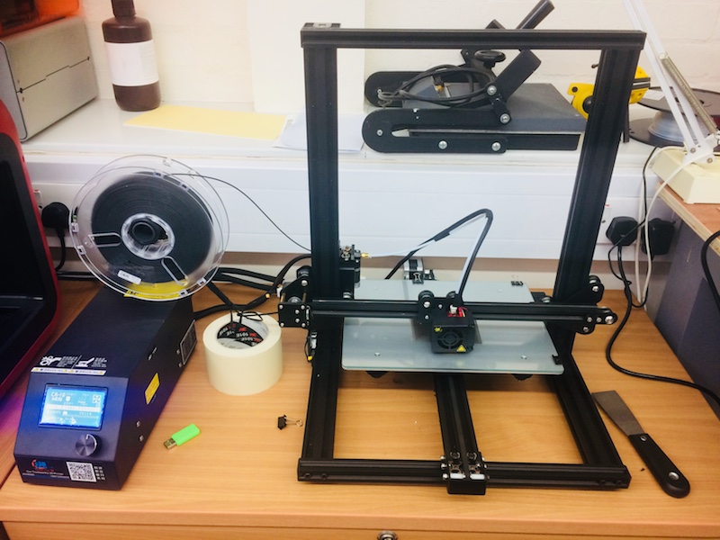
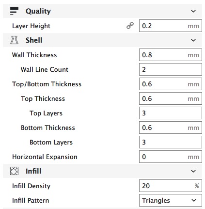
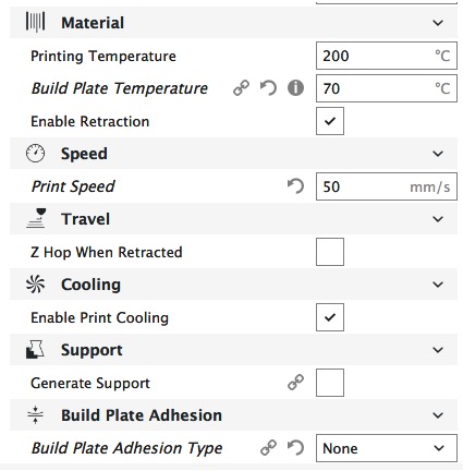
with the following basic settings used
and here's the first part I made, downloading the part from thingiverse as a good tester.
3D printed calibration block1.stl file
and here's the second part, testing a few extra details:
3D printed calibration block2.stl file
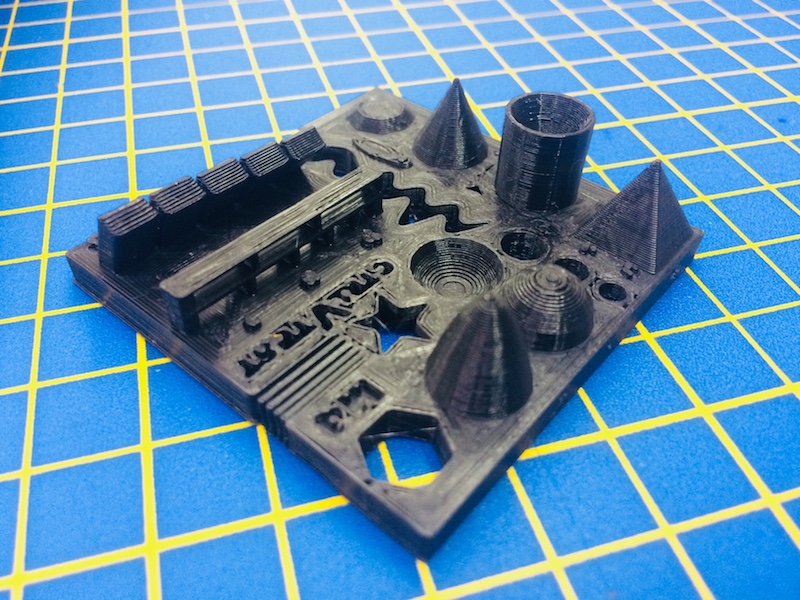
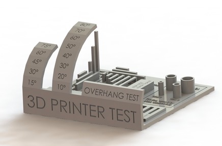
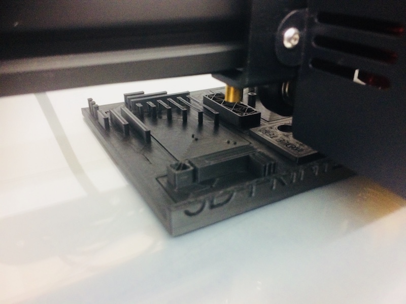
and here's the final set I printed (again with the .stl file downloaded from thingiverse) to specifically at the wall thickness and gap thickness achieved:
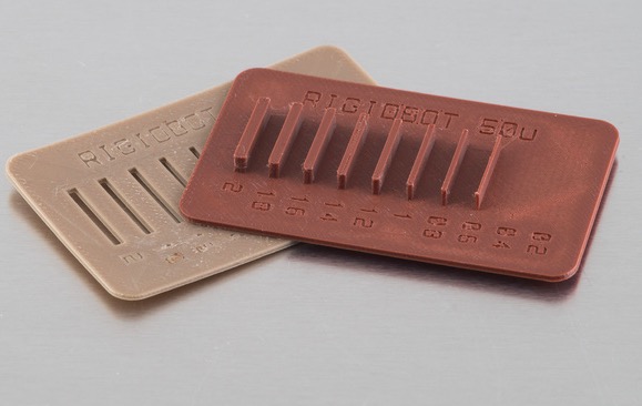
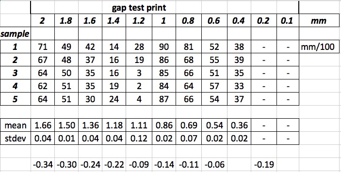
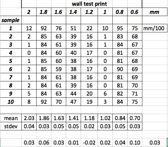
wall and gap test measurements.xls file to download
I do love 3d printing, it really is an interesting area for play! I've got a few publications from us playing around in this area in recent years, e.g:
- 1. Patel, N; Fagan-Murphy, A; Covill, D; Patel, B. 2017. 3D Printed Moulds Encompassing Carbon Composite Electrodes to Conduct Multi-Site Monitoring in the Entire Colon, Analytical Chemistry, 89 (21), pp 11690–11696. DOI: 10.1021/acs.analchem.7b03148.
- 2. Smith, C. Tollemache, N. Covill, D. Johnston, M. 2017. Take Away Body Parts! An investigation into the use of 3D-printed anatomical models in undergraduate anatomy education. Anatomical Sciences Education. DOI: 10.1002/ase.1718.
- 3. Hodder E, Duin S, Covill D, Dowell N, Cercignani M, Gelinsky M, Lode A, Bush P. 2017. Investigating the effect of sterilisation on the physical and cytocompatibility properties of alginate methyl cellulose applied as a cell-encapsulating material for primary bovine chondrocytes using 3D bioplotting. AOSpine Masters Symposium—Novel and Emerging Technologies in Translational Medicine September 22–23, 2017 Bern, Switzerland.
- 4. Morris, A. Fagan-Murphy, S. J. MacEachern, D. Covill and B.A. Patel, Electrochemical fecal pellet sensor for simultaneous real-time ex vivo detection of colonic serotonin signalling and motility, Scientific Reports, 2016, 6:23442. doi:10.1038/srep23442
- 5. Hodder E, Covill D, Dowell N, Best M, Cercignani M, Harris L. MRI-informed Biomimetic Design of Artificial Intervertebral Disc Scaffolds using 3D Bioplotting, UK society of Biomaterials conference, July 2016.
Individual assignment: Laser scanning
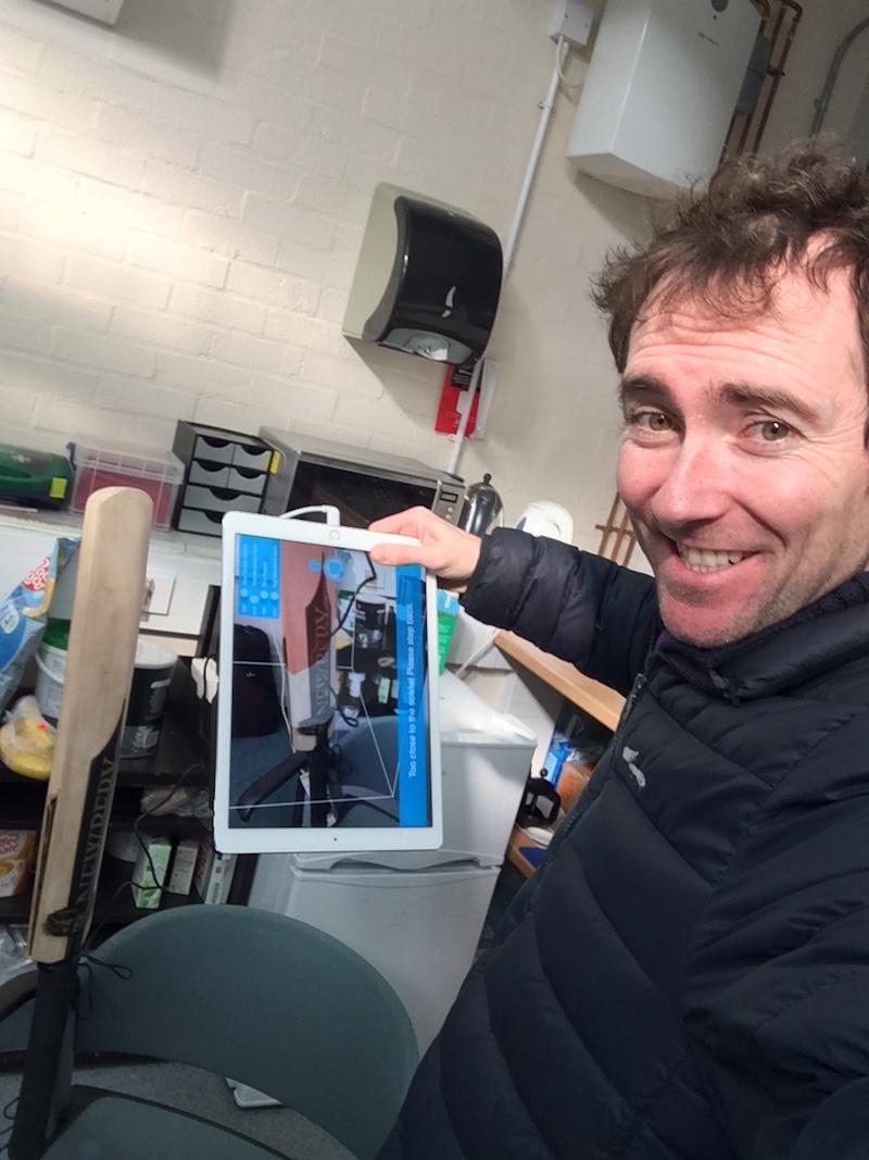
Scanning is a great way to capture geometry as an alternative to creating it in CAD software. We've found that it can complement CAD nicely, in particular if you are able to make something quickly out of foam with complex curvatures or with specific geometric requirements (e.g. fit a body part), then you can scan it in to digitally capture the geometry. There can be issues with getting closed shapes, and accuracy it typically not great, but more often than not we don't need...or indeed want, high accuracy. This week I wanted to scan my Newberry Mjolnir cricket bat. I've been using these bats for years, and they are the world's best cricket bats in my opinion. This particular bat is slightly broken (although I did clean it up beautifully and would be usable), but it will be used as a gift for our chairman terry 'the Shadow' who turns 60 today. Anyways, I want to scan in the bat, so that I can then use the scan later to generate a cutting pattern to machine into the back surface of a bat just like this using a milling machine.
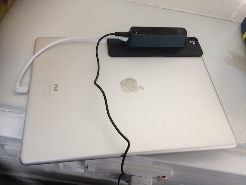
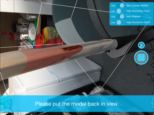
Here's our scanner, which is a Occipital Structure Scanner mounted to an IPad Pro.
I actually quite enjoyed the scanning process. I found it quite easy to work with.
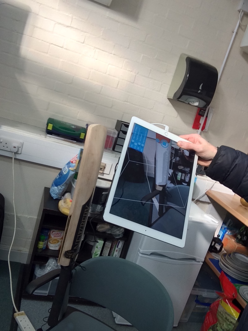
There's an icon on the ipad simply called "scanner", and then to get started (calibration was already done), you simply hit the scan button. It is like painting the object using the scanner, noting that you have to stay within the focal length of the scanner which is about 30cm from the object.
When you're too close, the object shows in red on the screen, then you simply move back a bit. Occasionally it will ask you to stop in one place so it can get a good view, and occasionally it will ask you to slow down. When done, there's an "email" button, and simply enter your email address and send it through to yourself.
It's worth noting though, that there's only one stab at it. If that email doesn't work, the file is lost. I tried to include some images into that email by adding attachments. In the end these were very large files (this ipad has a very high res camera so I discovered afterwards and the images were 10's of Mbs!!). So my scan didn't email through to me and it was lost.
other issues that I only realised was that you can specify the object's size by zooming in and out (pinching). This is very useful, as it can scan small objects (e.g. something that can fit in the palm of your hand), up to relatively large objects (e.g. small refridgerator sized). I learned this the hard way - and only at the very end of this process, after I'd done several scans of my cricket bat to capture the top, middle and bottom regions. In the end, I should only need two separate scans , and piecing them together in meshmixer should be a useful exercise for me.
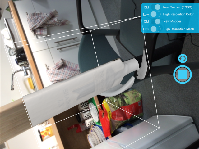
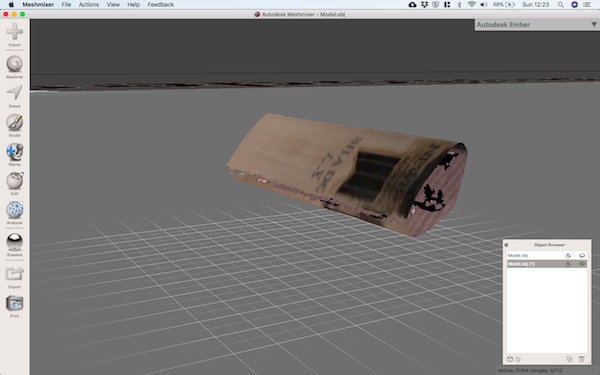
The first thing is to select outlying elements in the mesh and remove them, then do a cleanup. This image shows some nice nasties in there to be removed.
And here are the pieces brought together into a single file. You then need to reorient them so they align. This is done by eye.
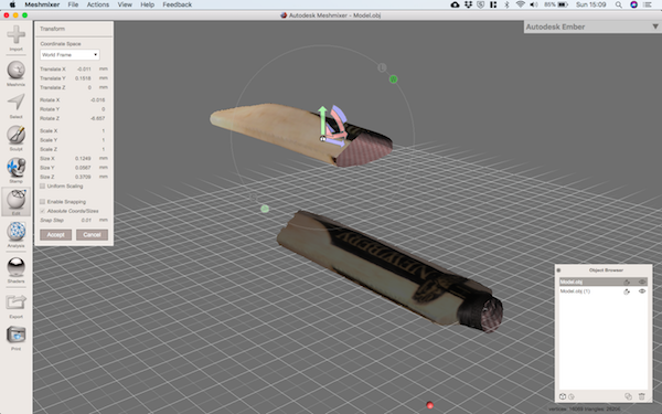
You can then remove any overlapping elements, and join them together.