Week 3 - Computer-Aided Design (CAD)
Assignment task for this week
model (raster, vector, 2D, 3D, render, animate, simulate, ...)
a possible final project, and post it on my class page.
Assignment summary
what I achieved/learned this week:
- a simple assembly drawing of my final project using parts and assemblies in Solidworks
- teaching myself Grasshopper
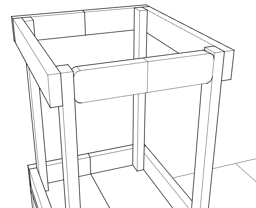
- creating a basic Rhinoceros frame model of my kitchen helper
- creating a full GH model of my kitchen helper design
- embedding the GH onto the shapediver site
My story this week...
This is where I will do a CAD model of my final project. I've created
quite a basic assembly model of all the components in Solidworks
which I've used quite a bit in the past. I thought I would use
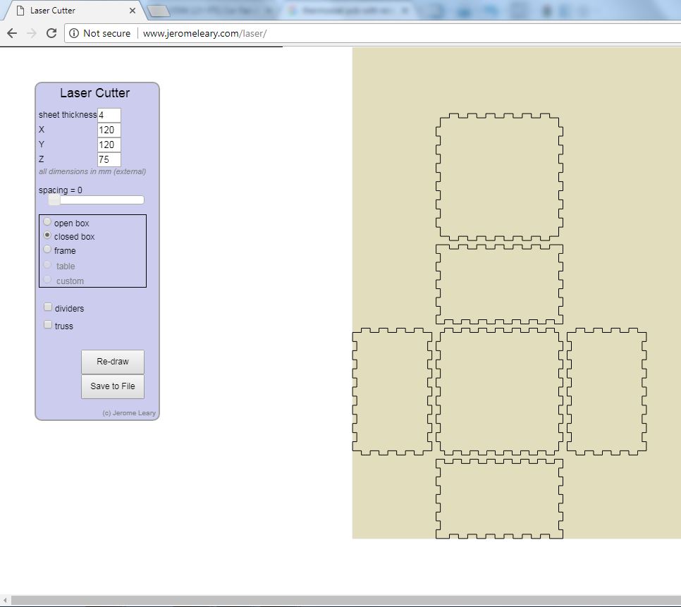
my colleague Jerome Leary's box generating programme (check it
out at www.jeromeleary.com,
it really does work well. I've not used it before, but referred
many people to use it in their projects. You simply put in the
key parameters and it spits out a net of the components in a
.dxf file. Simple. Here's what it looks like as a basic representation. The dimensions are sure to change.
I then opened this .dxf file in Solidworks, and saved it as
various part file names. Then for each, I simply extruded one of
the selected sketch profiles 4mm to give the 3D part as shown
below.
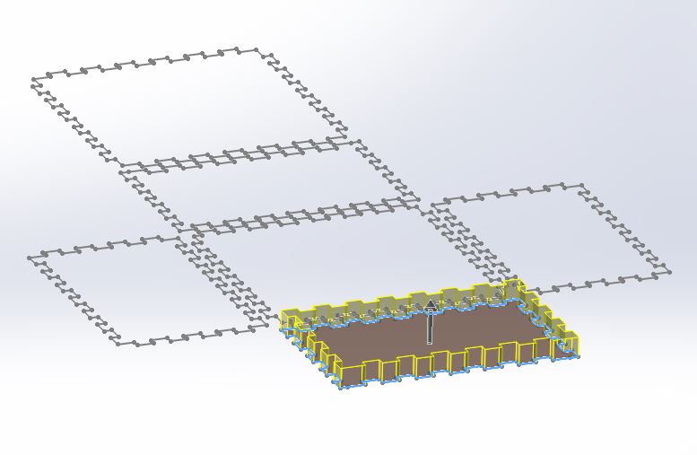
Extruding selected profiles in Solidworks and saving
out the various parts.
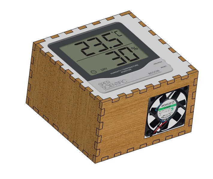
From there, I found a few images (square on) for a 12V heating
element, 12V fan, and thermostat PCB, and put these onto the
various parts as decals to show how it would look as an
assembly.
I then exploded the view, so all the parts can be seen.
I then thougtht I'd put this into a technical drawing to show
the Bill of Materials (BOM). 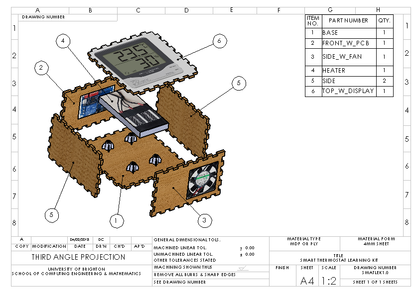
Here are the solidworks files to download (part/assembly/drawing)
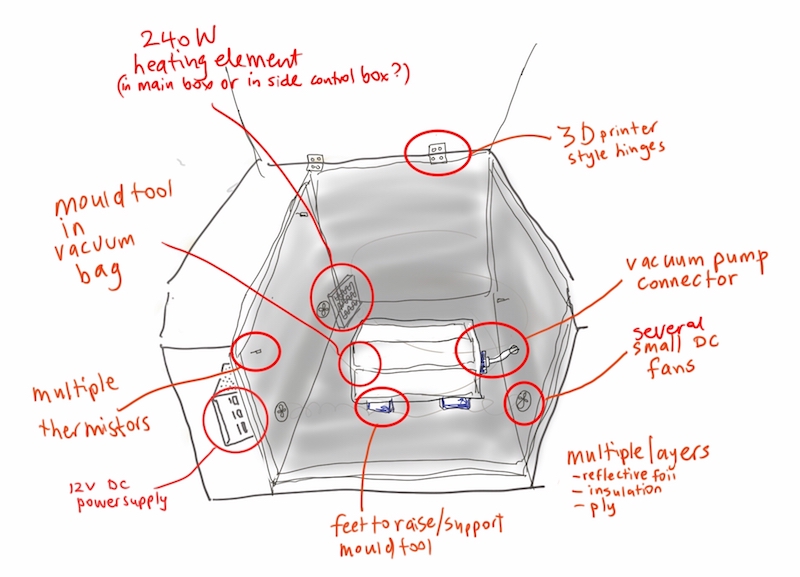
I also developed a quick 2D CAD model of the inside of the carbon fibre curing oven using Autodesk sketchbook on my tablet, but the only way I can export this file is using .jpg. or other standard image format. Here is the result.
And then used Photoshop to put together my final project slide, here's what it looked like:
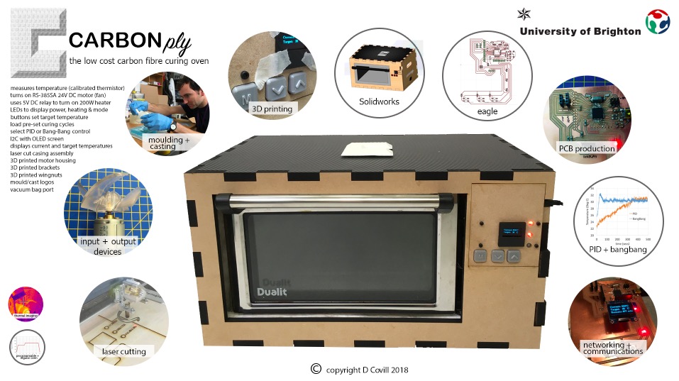
And here's the .psd file with all the layers for all the labels and images.
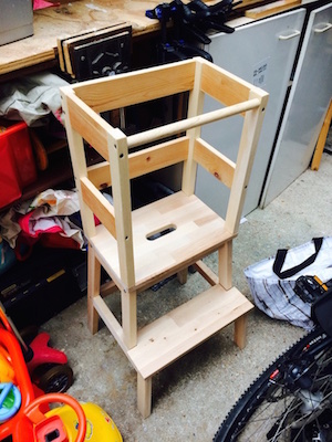
Kitchen helper Grasshopper model
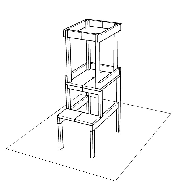
Ok, with that done, I thought I might also do some CAD work on my kitchen helper design, to try something that I've not done before. The kitchen helper is a small tower for kids so they can help in the kitchen. I've made a few of these, and have now done a basic CAD model in Rhino, I'd like to turn it into a parametrically controlled model.
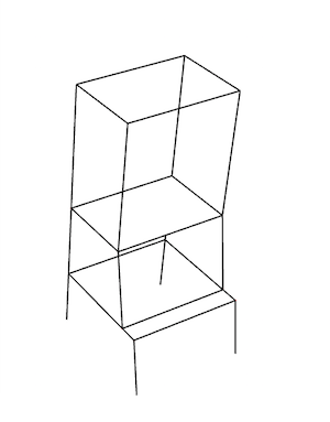
Here is the original Rhino file for the kitchen helper
It would be great to see if I can get it parametrically
controlled through a website, like tylko.com
who make shelves based on a web-based parametrically controlled
CAD model created in Rhino/Grasshopper. I'd also like to add in
which also has a net waste minimsation algorithm based on the
sheet material size.
I've just been chatting with Paul, one the guys in the fablab,
who's got some good experience with grasshopper.
He showed me the shape diver
which looks absolutely brilliant for what I need! It will host a
3D interactive model of a CAD model, with full slider control of
a parametric model! they offer a free service for non-commercial
use, but also a paid service to actually sell products through
their site. I was very impressed! You can even embed it on your
own site, here's an example that they have given:
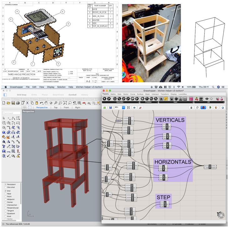
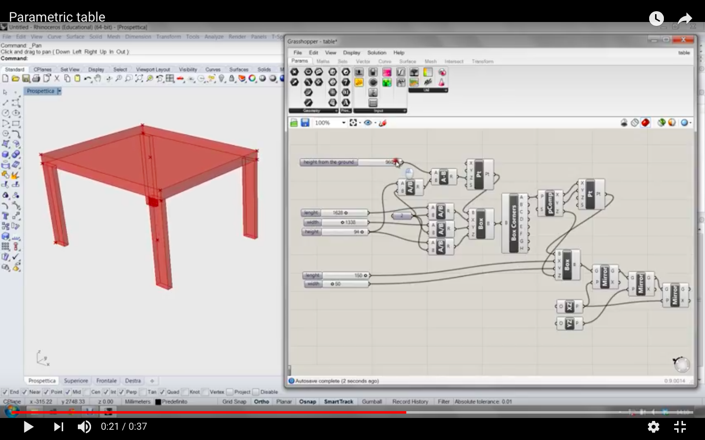
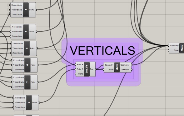
I got so excited by this possibility I went onto Grasshopper and
created a basic parametric set of blocks which are driven by the
material thickness, just to figure out how to relate the two
parts.
In theory, I can now scale this up for the various other parts,
and mirror them (to save the number of components needed). Here
are some picture of the material thickness and height parameters
changed in Grasshopper with a basic sliders and it shows the
relationship between them that I was after.
I've just discovered that the MAC WIP version of Grasshopper in
Rhino doesn't seem to work with shapediver, so I will need to
open the grasshopper definition on my PC and resave it, and hope
that this works.
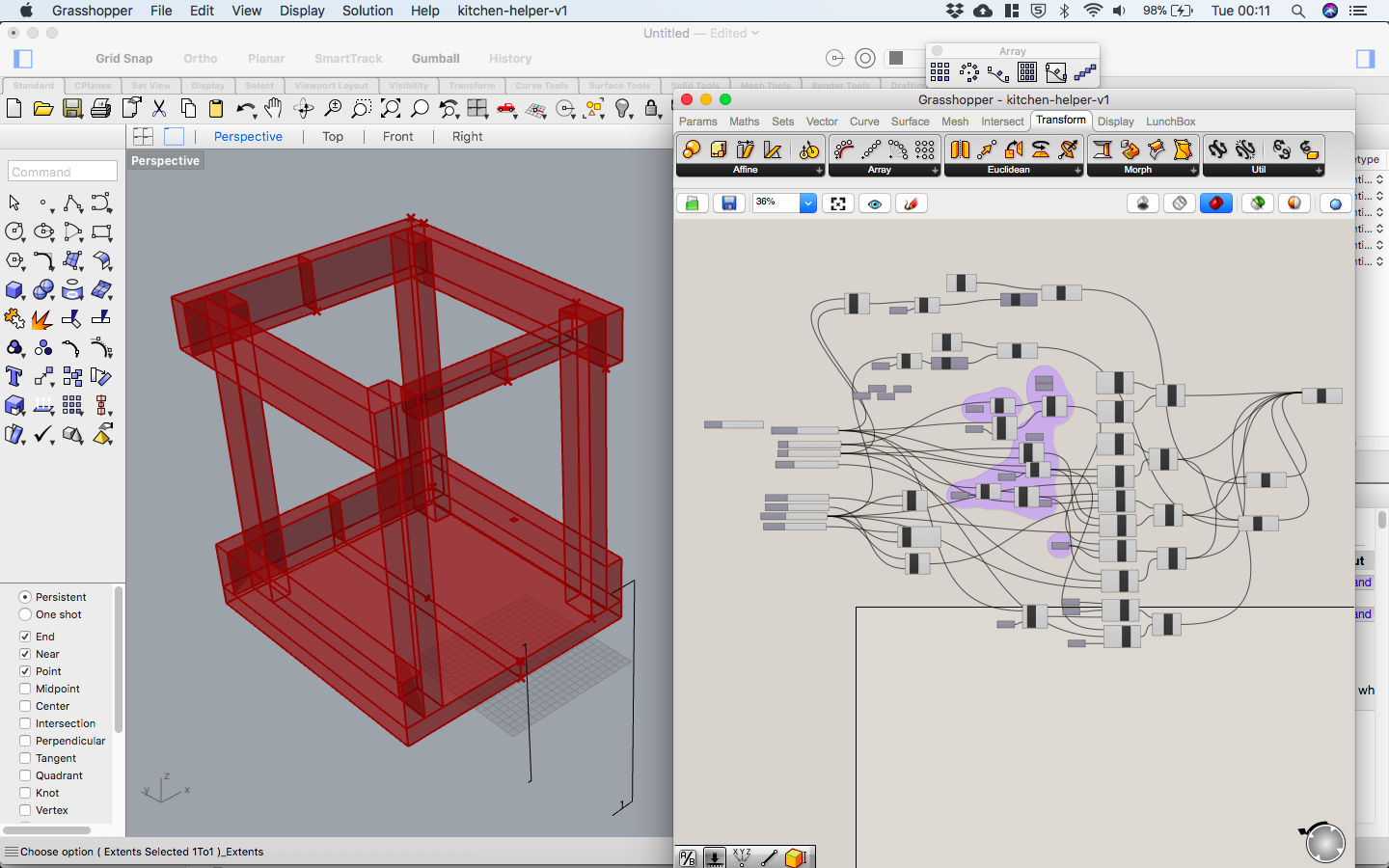
I've now resaved this on my PC and it works! It doesn't look
much, but it's only a very basic test. Here is a basic test model, testing out my ability to
parameterise the lenght, width, depth of two basic parts
assembled together. Now I can roll this approach out for the
full design! I've made some real progress with my Grasshopper
model, I've done the top half of the kitchen helper and it works
ok. I just now need to finish off the bottom half and upload the
definition to ShapeDiver.
I went back a few weeks later and did it!!! Here is the basic design now complete. Still plenty to do, but I'm happy with achieving this stage...but boy does Grasshopper take a lot of time compared to other parametric software like Solidworks. I estimate this would take me about an hour in Solidworks, and it probably took me 20 hours in Grasshopper (including the learning). I also want to try to render this, and to create it in fusion also for comparison.
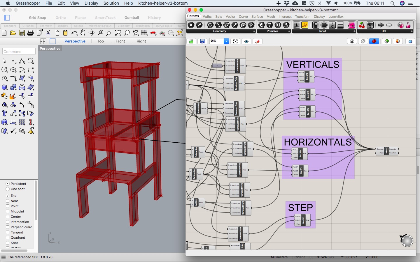
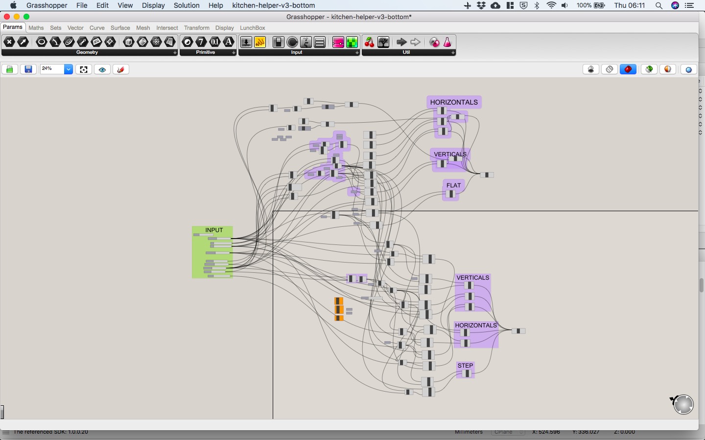
Here's the grasshopper definition. I could definately tidy this up somewhat, but perhaps it would be better to start again. Defining the construction points (Construct XYZ component) took a long time, and I tried to use existing co-ordinates (e.g. x from previous point made), but finding the root of the value took a long time, especially as the complexity increased. If there was a way to SELECT the corner point of an existing box easily (using GUI) that would help. Also the design itself is very blocky, I would like to do something a little less harsh (fillets, angles), but that's to be done over another cup of coffee (or 3),
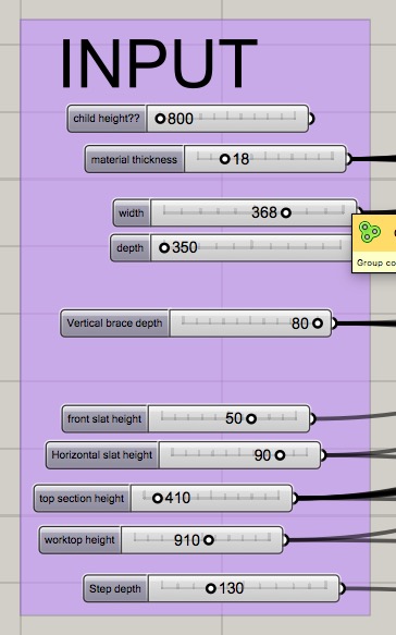
The inputs also could be improved. The relationship between the top and bottom halves is a little clunky I feel. It really should just be one input (overall height). Originally I was going to link the height of the top with the anthopometric data of the child (based on their height), but perhaps another time again over some more coffee....or I might do this in Solidworks where it's quicker! Hmm, or try to create a slider in Fusion using scripting...
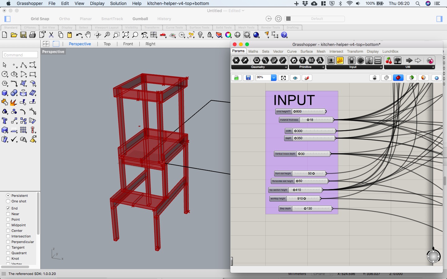
Here's the design adjusted a little to show some variation.
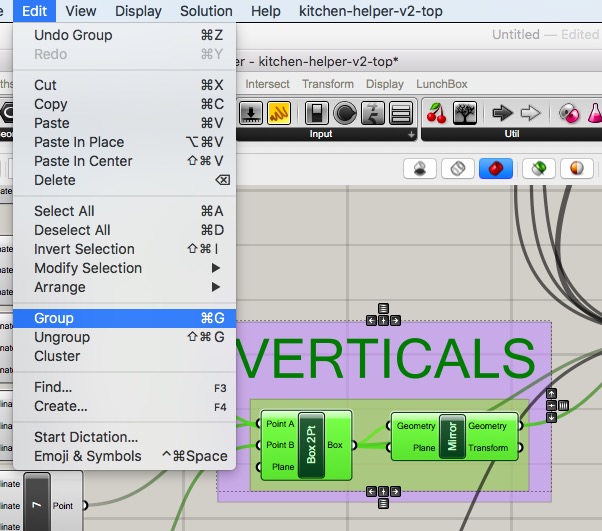
I also added some labels using the SCRIBBLE definition to make the layout a little clearer.
and using groups to group the scribble and the components really does help to chunk it up.
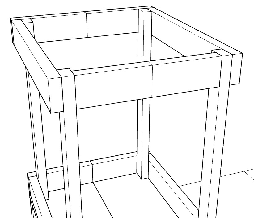
And after using the BAKE component to bake all the boxes (surely there's a way to do this all in one go?), here's a basic pen render in Rhinoceros.
With some detail that I want to explore all over...here's a taster...
And here is the embedded interactive parametric model from Shapediver..in full flow! It's best to open it full screen to get the best effect.
here is the .gh grasshopper definition file to download
So what's left to do:- add in the design the bottom half in grasshopper - DONE!
- add in the screws functionality
- render it in ply to make it look nicer
- figure out how to generate .dxf file from grasshopper
- figure out how to nest this automatically with an input material size...then possibly optimise this using an algorithm?
- redesign the grasshopper to be much simpler, and to include milling details, and press fit
I really enjoyed the recitation on Usability design. We have
just started our 'usable' design project with first year product
design students, so it was very timely. It got me thinking about
the Gestalt laws...and another (very similar) set of rules I
learned ages ago called 'CRAP' rules, which stands for Contrast,
Repetition, Alignment and Proximity. Anyways, the 4 main Gestalt
laws from today were:
1Proximity (2 paired lines)
2Closure (3 rectangles)
3Simplicity (repeated triangles, squares, circles)
4Experience/legacy (e.g. trash can on software)
It also got me thinking that for my Smart Thermostat Learning
Kit (I really should just refer to it as SMATLEK - although I
don't really like that acronym), I really need to start thinking
about colours. I will try out colour.adobe.com ...and try out
some Kula colour schemes...and I'd also like to try out using
the feature where you can chose a colour palette based on a
picture. To complement the CAD, I should also create some quick
prototypes in card to get feedback from students - both here on
campus but also elsewhere. As suggested in the Usability
recitation I should also write a paragraph success story (and
test it) and draw a 3-panel success comic and (and test it),
possibly then do some more testing with fake features using
wizard of oz technique.
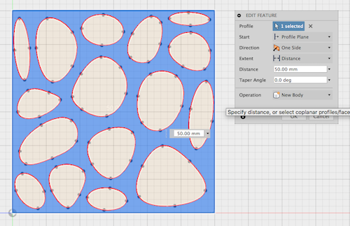
other cad things of interest
voronoi generator in fusion 360, could be useful. It has some basic parameters, then creates a sketch. It is limited in that it only fits the shapes within a rectangular box, not a predetermined closed sketch, but still could be useful.