Week 16 - Machine Design
Group assignment
Actuate and automate your machine.
Design a machine that includes mechanism+actuation+automation, and build the mechanical parts and operate it manually.
My role this week can be summarised as follows:
- leading on the documentation for the project
- sorting out the project management, planning, issues tracking etc
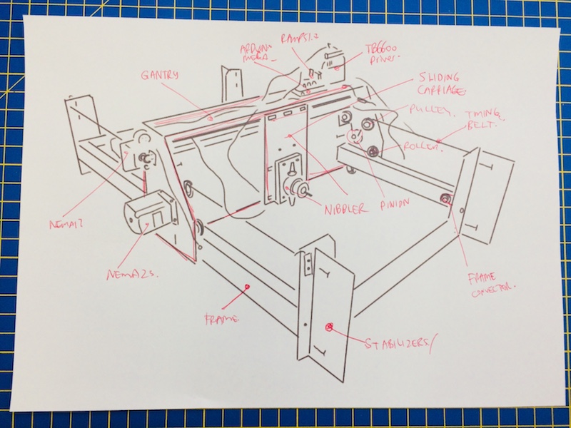
- design and make belt holding system
- installing the belts to drive the gantry
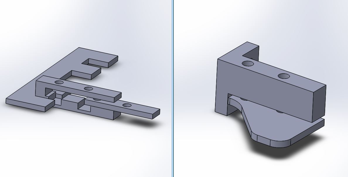
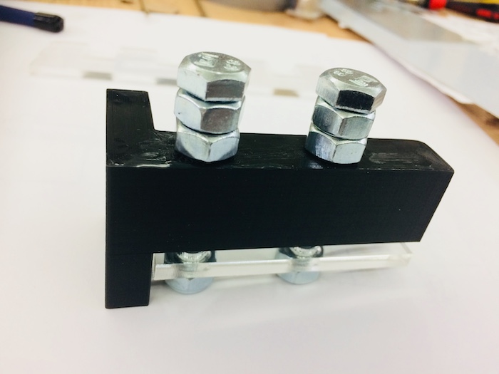
- designing and making the clamp to hold the material to the frame
- logo design
- laser cutting updated parts, editing updated part files and laser cutting parts
- wiring and mouting endstops and testing these with printrun software
- testing drive system and motors and calibration
- re-assembly and testing
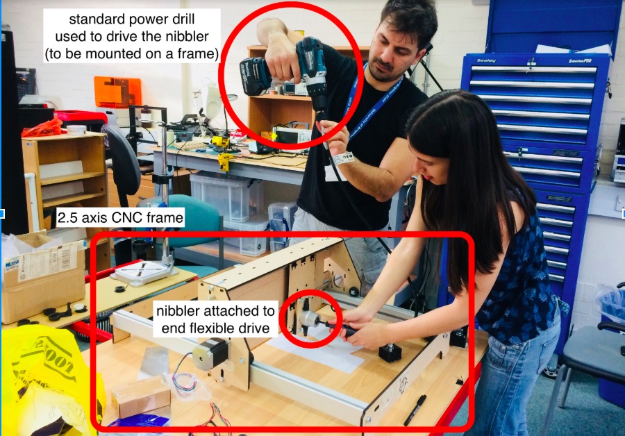
Just to recap from last week...Metal cutting can be a dangerous, expensive, or in accurate undertaking. We were aiming to create a CNC metal cutter for thin sheets of aluminium and steel that we could use for project work. Ideally the machine would be quite small in order to fit into the lab, but we are aiming to make it scalable to larger sizes. We were fascinated by the nibbler tool when we saw it, thinking that if mounted to a computer controlled machine, it could make a relatively accurate, low-cost metal cutter for our lab. After a little research, we did not find any other attempts at this, so either we are breaking new ground here, or there are some very good reasons why this is not a good idea!
Here is a link to our lab's page which includes links to all our group assignments.
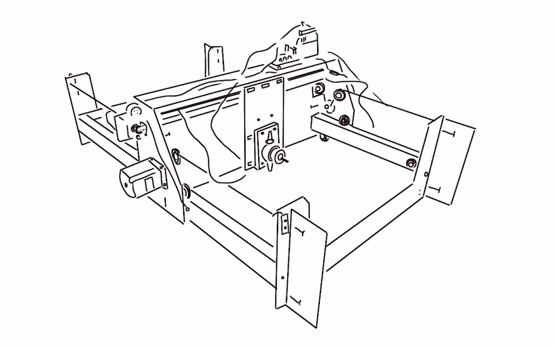
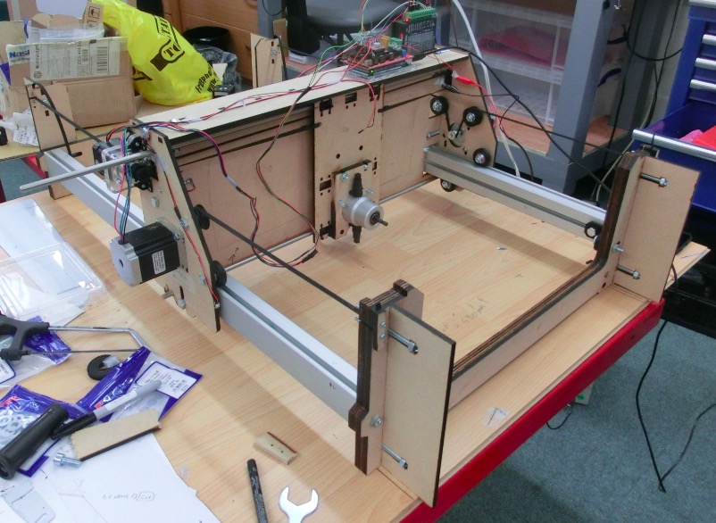
Last week we designed the machine which includes mechanism+actuation+automation, and we built the mechanical parts and operated it manually. This is what it looked at the end of the first week (well, we actually had all the belts and pulleys all connected also.
Here are the latest part files for download
And here's how the design has progressed this week:
One of the first things to do was to actuate the motors, here's the result of the first test!
Here’s some videos of us testing the stepper motors to drive in X then Y and then both X and Y:
We’ve achieved actuation!! Here is some initial testing for machine calibration using a pen to draw a line that can be measured. We noted that a 100 mm line was actually coming out as about 110 mm, so we’ll need to do more checks on this and adjust the calibration settings.
A video with a bit of a discussion about controlling the nibbler:
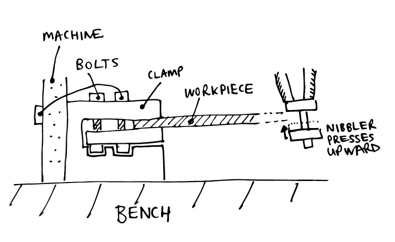
We really needed a system to clamp the workpiece to the machine itself. Either that, or we need to clamp the workpiece to the worktop...and clamp the machine down too! In time, that may well be a suitable solution, but clearly we want to give ourselves some challenges, so we went for the former option. Anyways, we think we’ve come up with a neat solution that:
- Clamps securely to the same Y-position at one end of the machine
- Keeps the vertical height the same, relative to the underside of the clamp (the nibbler pulls the workpiece upwards when it is cutting)
- Clamps the workpiece securely from both sides. These aren’t currently clamped to each other (acceptable) or the machine (ideal), but that is a future development. For the time being we’re able to clamp/screw these to the make-shift floorboard bench for added stability.
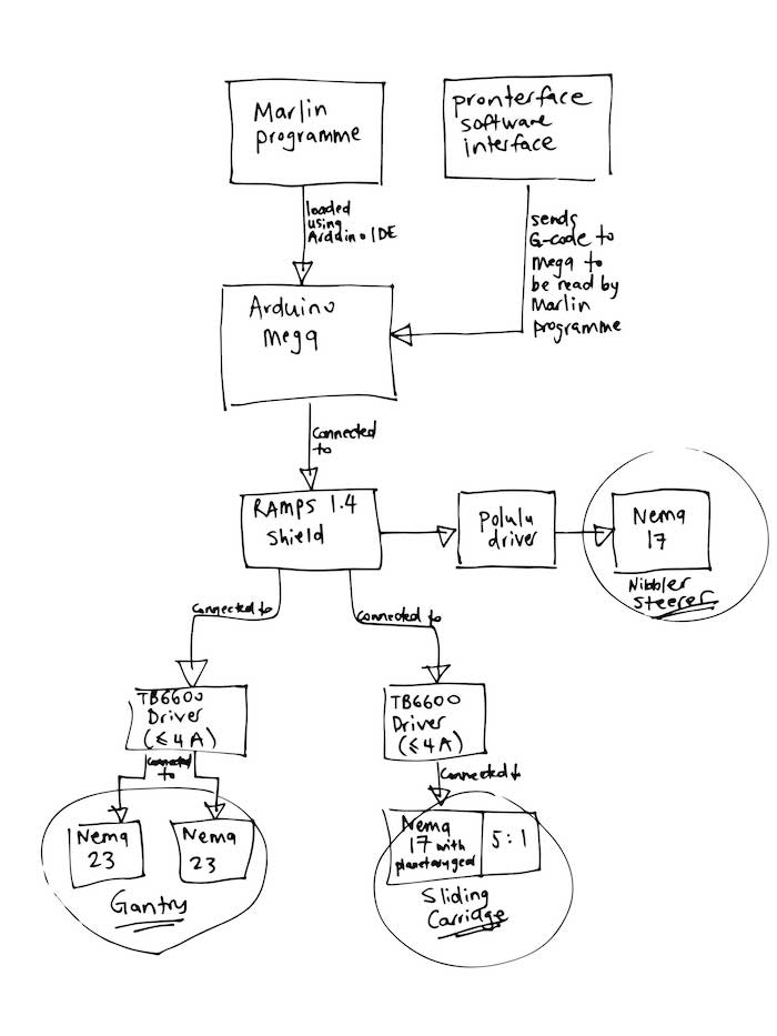
I wanted to communicate how the machine would be controlled, so I drew this flowchart:
Characterising our machine Error budgeting Measuring errors in structural loop Enabling feedback with sensors Closed loop vs open loop motors and rotary encoders Static paths Dynamic paths