Week 14 - Networking and communications
Group assignment
send a message between two projects.
Here is a link to our lab's page which includes links to all our group assignments.
Below is my video using the group networking setup.
Individual assignment
design and build a wired &/or wireless network connecting at least two processors.
Assignment summary
what I achieved/learned this week:
- designed a wired network with a master and several slaves and got them to talk to each other using I2C
- used serial monitor to input commands to drive the intermittent turning on/off of LEDs on all boards (ATmega32u4)
- created a network to control two types of slaves (ATmega32u4 and ATtiny85)
Introduction
The key this week is a simple serial bus, but I2C could be a good thing to try.
Interesting notes: I2C was proprietary. It is synchronous, where boards don't need to agree on timing. Arduino has an I2C library.
SPI is used on our programmer board (MOSI, MISO, SCK). Arduino has an SPI library. Talking to SD cards is a good example of SPI protocol.
Interesting to note the need for impedence matching (between electrical load and its corresponding signal source), since radio is the transmission and reception of electromagnetic waves of radio frequency. Then, looking further into it, Electromagnetic waves are created as a result of vibrations between an electric field and a magnetic field. They are formed when an electric field comes in contact with a magnetic field. The electric field and magnetic field of an electromagnetic wave are perpendicular to each other...and are perpendicular to the direction of the EM wave!
I thought a good start this week would be to try to have a go with connecting two boards using the I2C communications protocol, since so far I've only used serial (Serial Peripheral Interface - SPI). The Inter-integrated Circuit (I2C) Protocol is a protocol intended to allow multiple “slave” boards to communicate with one or more "master" boards...ie it's great for connecting multiple boards! It's also synchronous meaning that the boards don't need to agree on the timing between them. The sparkfun i2c page provides a good introduction.
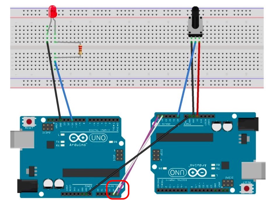
I found this tutorial which uses I2C to communicate between two boards, where one board will send a value to dim or brighten an LED on the other board. I thought this seemed like a good introduction for me. It's worth noting that the Arduino sketches calls the Wire library which enables the the boards to communciate using the I2C protocol.
Here is the circuit for this exercise, noting that the A4 and A5 pins are connected between the baords. The A4 pin is the SDA (dataline) and the A5 pin is the SCL (clock line)
Here is the code for the master board (my fab leo) board, noting that you need to connect each board to the computer when you upload the programme, then you connect the slave boards to the master board to piggyback power them using either the computer, or a separate power supply. If the exercise requires more power than simply turning on LEDs, then each board may need their own power supply.
#includeint x = 0; int sensorPin = A0; int sensorValue = 0; void setup() { Wire.begin(); // Start the I2C Bus as Master Serial.begin(9600); } void loop() { sensorValue = analogRead(sensorPin); Serial.println(sensorValue); Wire.beginTransmission(9); Wire.write(sensorValue); // transmit to device #9 delay(1000); Wire.endTransmission(); // stop transmitting }
Here is the slave code for a generic UNO that I plugged into my board.
#include// Include the required Wire library for I2C int LED = 11; int x = 0; void setup() { pinMode (LED, OUTPUT); // Define the LED pin as Output Wire.begin(9); // Start the I2C Bus as Slave on address 9 Wire.onReceive(receiveEvent); // Attach a function to trigger when something is received. Serial.begin(9600); //bit rate for data transfer over Serial communication } void receiveEvent(int bytes) { x = Wire.read(); // read one character from the I2C } void loop() { int ledPWM = map(x, 0, 255, 0, 1023); //potentiometer value from sensor analogWrite(LED, ledPWM); Serial.print("X is: "); Serial.println(x); Serial.print("PWM is: "); Serial.println(ledPWM); delay(1000); }
I connected everything up as shown here, then programmed the boards.
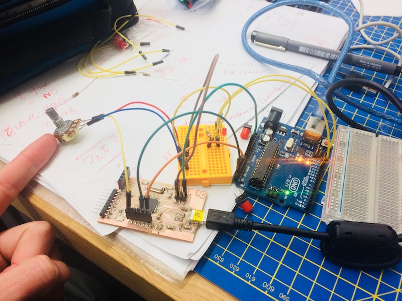
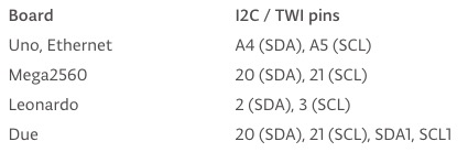
Disappointingly, I couldn't get it to work. I was slightly sceptical about the tutorial since there were a few errors in the code (e.g. Wire.h was not spelled with a capital W - which meant the programme didn't upload and stumbled at the first possible hurdle). There were no comments on the tutorial either, so I didn't have any evidence to suggest that it had been tried and tested. That said, the code seemed ok after a bit of tidying, and my scepticism was also founded on my own setup. Because my board had been modified to include a resistor and thermistor, I thought I would need to change the pins from A4 and A5 to A3 and A4...I tried this but of course it didn't work. I was only later that our Guru Luiz pointed out that A4 (SDA) and A5 (SCL) are used for the arduino uno (ATtiny 85), not the arduino leonardo (ATmega32u4) chip. Instead, I SHOULD have connected it to pin 2 (SDA) and pin 3 (SCL). Here's the official guide:
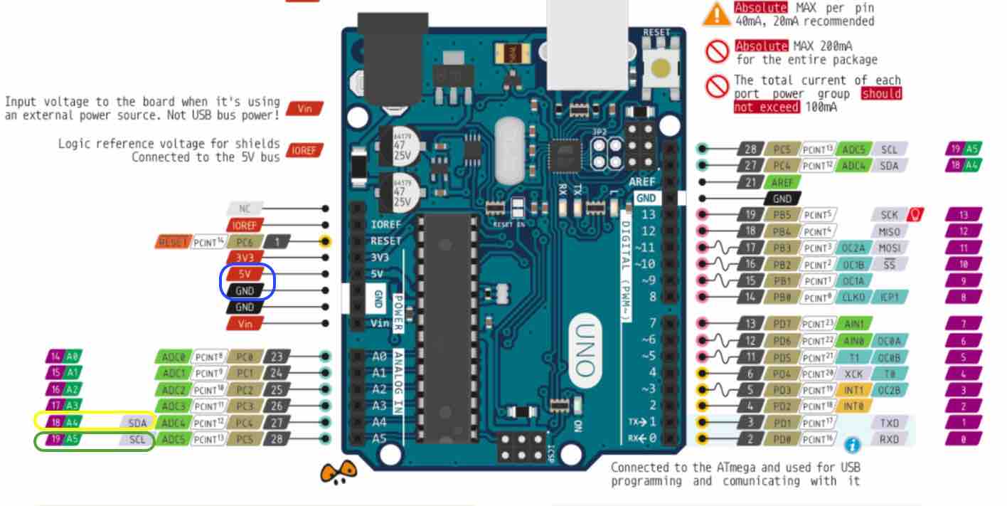
and the is the pin diagram for the Uno, with A4/A5 highlighed.
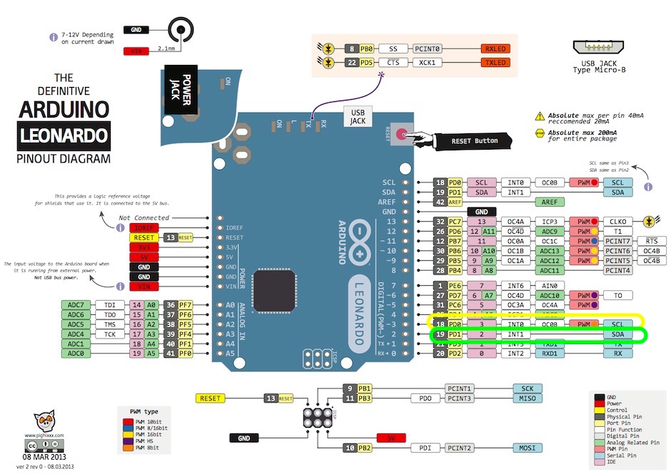
and the is the pin diagram for the Leonardo, with A0/A1 highlighed.
so the problem all along was it seems the pins I used for the I2C...bummer!
Moving onto the next exercise, I worked with Luiz to try something different, and slightly more ambitious, based on a little exercise he'd done previously...keeping a keen eye on the pins needed this time!
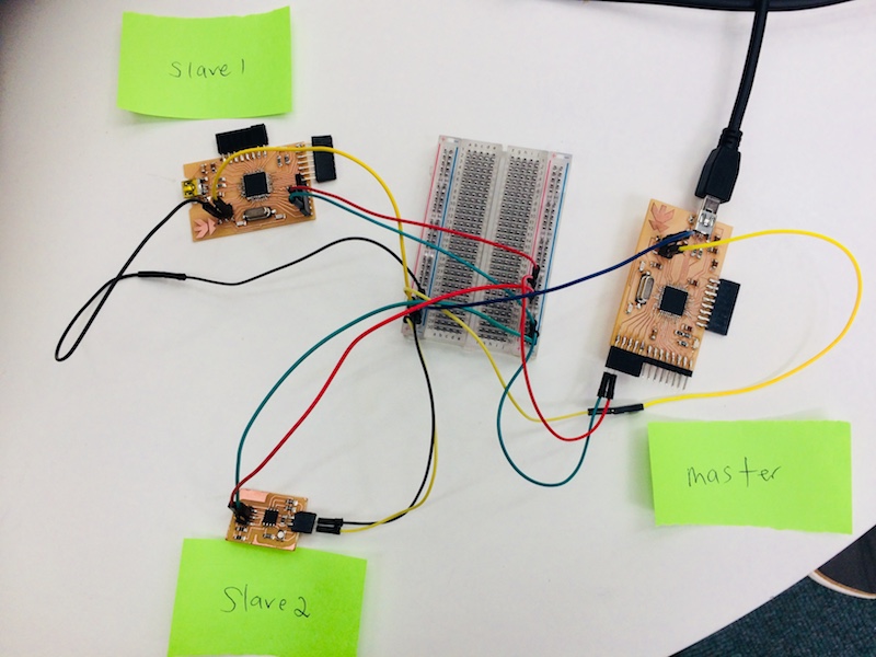
We connected up 4 boards using the I2C protocol, where we would use the serial monitor to turn on and off the built in LEDs for each board in turn by simply typing the numbers 1-6 into the serial monitor and hitting enter.
Here is the code for the master of all the slaves!!!
//i2c code to connect 3 other boards to turn on and off lights in turn // by typing 1, 2, 3, 4, 5, 6 #includevoid setup() { Serial.begin(9600); Wire.begin(); } void loop() { while(Serial.available()) { char c = Serial.read(); if(c == '1') { Wire.beginTransmission(5); //begin transmitting to address 5 Wire.write('H'); Wire.endTransmission(); digitalWrite(13, HIGH); } else if(c == '2') { Wire.beginTransmission(5); Wire.write('L'); Wire.endTransmission(); digitalWrite(13, LOW); } if(c == '3') { Wire.beginTransmission(6); Wire.write('H'); Wire.endTransmission(); digitalWrite(13, HIGH); } else if(c == '4') { Wire.beginTransmission(6); Wire.write('L'); Wire.endTransmission(); digitalWrite(13, LOW); } if(c == '5') { Wire.beginTransmission(7); Wire.write('H'); Wire.endTransmission(); digitalWrite(13, HIGH); } else if(c == '6') { Wire.beginTransmission(7); Wire.write('L'); Wire.endTransmission(); digitalWrite(13, LOW); }}}
Here is the code for slave 1, address 5.
//i2c Slave1, address 5 #includevoid setup() { Wire.begin(5); //specifying that this board is address 5 Wire.onReceive(receiveEvent); pinMode(13, OUTPUT); digitalWrite(13,LOW); } void loop() { } void receiveEvent (int howMany) { while(Wire.available()) { char c = Wire.read(); if(c == 'H') {digitalWrite(13, HIGH); } else if(c == 'L') { digitalWrite(13, LOW); } } }
Here is the code for slave 2, address 6.
//i2c Slave2, address 6 #includevoid setup() { Wire.begin(6); Wire.onReceive(receiveEvent); pinMode(13, OUTPUT); digitalWrite(13,LOW); } void loop() { } void receiveEvent (int howMany) { while(Wire.available()) { char c = Wire.read(); if(c == 'H') {digitalWrite(13, HIGH); } else if(c == 'L') { digitalWrite(13, LOW); } } }
Here is the code for slave 3, address 7.
//i2c Slave3, address 7 #includevoid setup() { Wire.begin(7); Wire.onReceive(receiveEvent); pinMode(13, OUTPUT); digitalWrite(13,LOW); } void loop() { } void receiveEvent (int howMany) { while(Wire.available()) { char c = Wire.read(); if(c == 'H') {digitalWrite(13, HIGH); } else if(c == 'L') { digitalWrite(13, LOW); } } }
and here are the files for download:
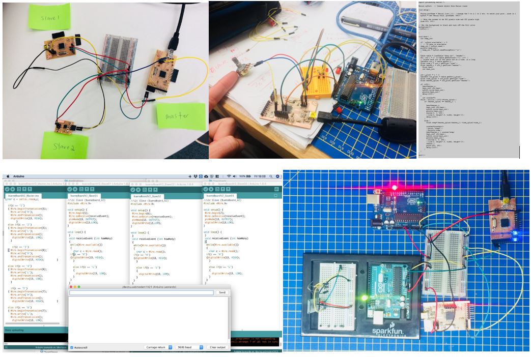
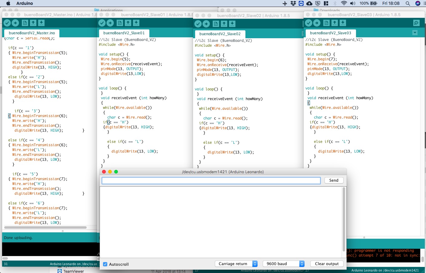
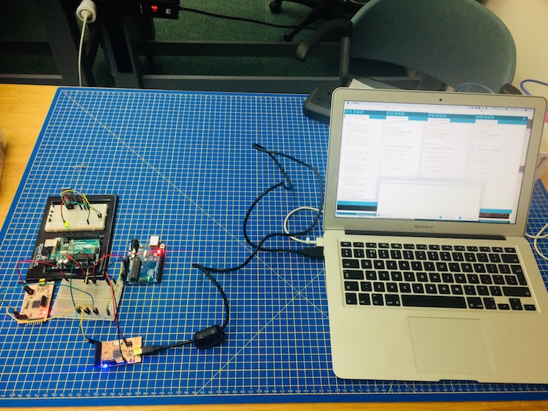
Here's how it all looked on the screen, then I connected each board in turn and uploaded the respective sketch, making sure I got the correct code with the correct board. All Grounds were connected to each other, all VCCs were connected to each other, and similarly all SCR pins were connected to each other, and all SDA pins were connected to each other. Note that for I2C communications, the SCR and SDA pins are used, along with GND and VCC.
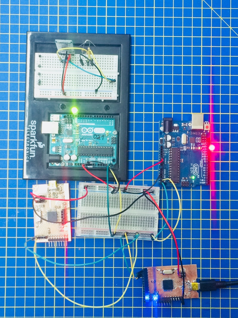
and here's the real circuit setup.
and here it is with all the lights on (i.e. 5 enter).
and here's the token video of the process. Very satisfying! It's also worth noting here that I was curious about the numbers used for addressing each board (I used 5,6,7 for the slaves above). I wondered if these numbers were arbitrary, so I changed the address of slave1 to be 500 in both the master sketch, and the slave1 sketch, and it did exactly the same thing...so yes, the address numbers are arbitrary, as long as they are consistent.