Week 12 - Output devices
Group assignment
measure the power consumption of an output device.
Here is a link to our lab's page which includes links to all our group assignments.
Individual assignment
add an output device to a microcontroller board you've designed, and program it to do something.
Assignment summary
what I achieved/learned this week:
- created a circuit using my board, to turn a heater on/off using a relay, using the thermistor as an input device to measure the temperature and the circuit compared this value against a pre-set value
- measured the power output of the small heating element by measuring the current being drawn through it (in series), and the voltage across it (in parallel), and multiplying the two together.
Introduction
Output devices, otherwise known as actuators, DO things. This can be to move (translate/rotate), make a noise, produce light, produce heat, produce current etc.
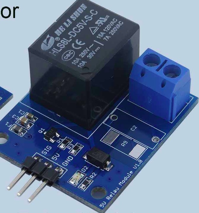
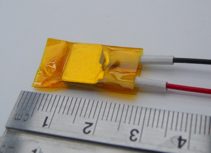
This week I wanted to tie this to my final project, focusing on producing and controlling heat. Here's the relay shield I want to try out with last week's circuit (to measure temperature), with a basic heating element (5V/12V/24V up to 230 degreesC). This relay should work also with my final project, but these heating elements are only low power (3-12 Watts) and so won't be powerful enough for my final project (more like 150-200 Watts needed, e.g. 24V and 8.3 Amps will deliver 200 Watts).
I then managed to get the relay to work using the sound sensor as input, where if a threshold sound level is reached (e.g. a clap or whistle), the relay will then turn on an LED which is powered using an external power source (in this code simply the 3V power supply on the arduino uno board.
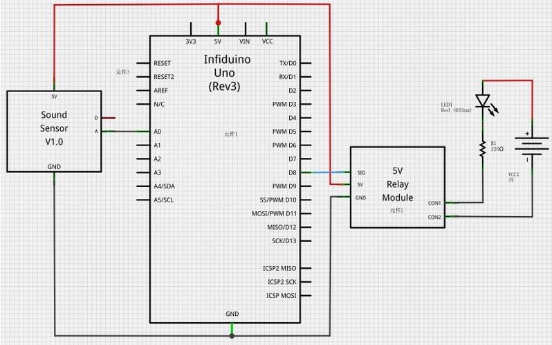
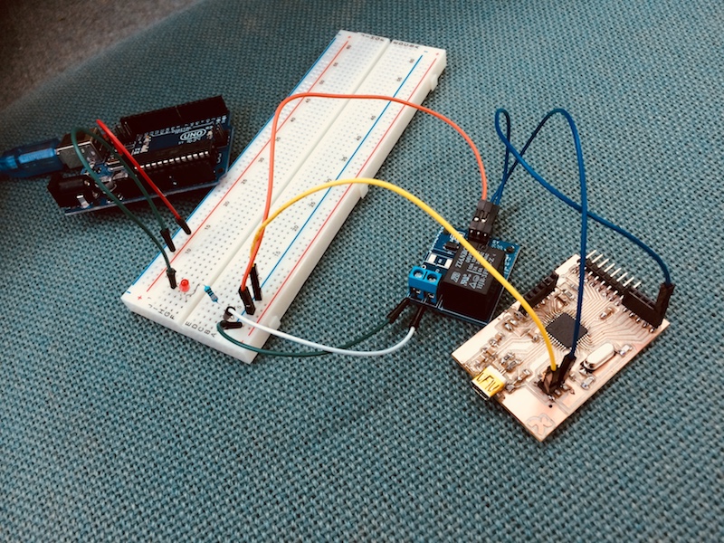
and here's the basic setup with the sound sensor, the relay driving the LED, and the LED on the breadboard.:
And here's the code:
/*
  Relay controlling
  Reads an analog input on pin 0, prints the result to the serial monitor, and use it to control the Relay through D8
*/

void setup() {
  // initialize serial communication at 9600 bits per second:
  Serial.begin(9600);
  pinMode(8,OUTPUT);
}

// the loop routine runs over and over again forever:
void loop() {
  // read the input on analog pin 0:
  int sensorValue = analogRead(A0);
  // print out the value you read:
  Serial.println(sensorValue);
  //If there is a big sound nearby, make the led light for one second.
  if(sensorValue>500)
  {
    digitalWrite(8,HIGH);
    delay(1000);
  }
  else
  digitalWrite(8,LOW);
}
here is the controlling relay.ino file to download
And here's a video
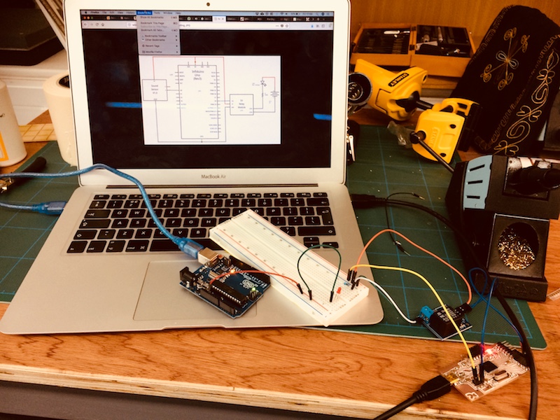
And here's it working with the serial monitor and the leads a little tidier on the breadboard.
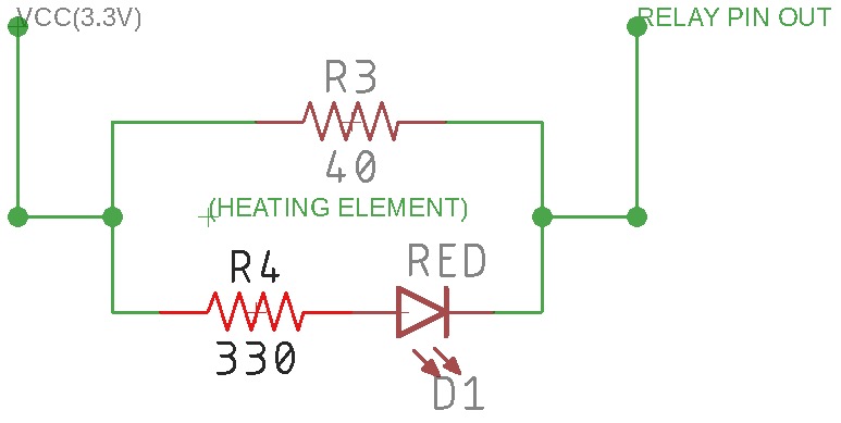
I've now managed to get the relay to turn on an LED using the temperature read by the thermistor. When the temperature drops below 23degrees, the relay turns the LED on. When the temperature rises above 23degrees, the relay turns the LED off. Here's the output circuit from the relay.
And here's the setup
Here's the code:
// the value of the 'other' resistor
#define SERIESRESISTOR 10000

// What pin to connect the sensor to
#define THERMISTORPIN A5

void setup(void) {
  Serial.begin(9600);
  pinMode(3,OUTPUT);
}

void loop(void) {
  float reading;
  float temperature;

  reading = analogRead(THERMISTORPIN);

  // convert the value to resistance
  temperature = -0.225*reading+231.65;     // formula to convert analogue reading to temperature (Deg C)
  Serial.print("The temperature is ");
  Serial.print(temperature);
  Serial.println(" Degrees C");
  Serial.println(" ");
  delay(1000);
  if(temperature>23)
  {
    Serial.println("HIGH TEMP, HEATER IS OFF");
    digitalWrite(3,LOW);
    digitalWrite(LED_BUILTIN, LOW);   // turn the LED on (LOW is the voltage level)

    delay(1000);
  }
  else{
  Serial.println("LOW TEMP, HEATER IS ON");
  digitalWrite(3,HIGH);
  digitalWrite(LED_BUILTIN, HIGH);   // turn the LED on (HIGH is the voltage level)
  }
}
here is the thermostatic control of LED and HEATER.ino file to download
and here's the video! Next step is to use a heating element in addition to the LED.
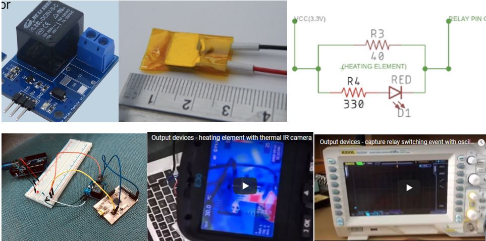
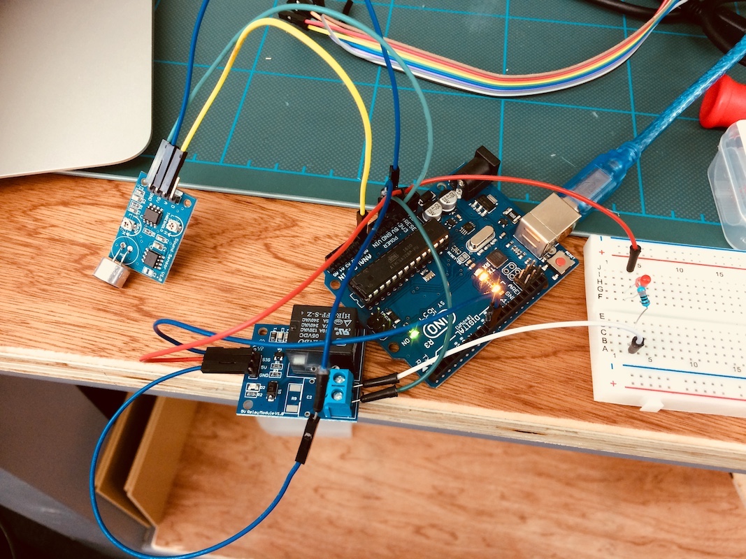
thermostatic control with thermistor, relay, LED and now heating element added in parallel with the LED+resistor.
Seeing the heating element and microcontroller with the IR thermal imaging camera.
measuring current and voltage with multimeter and oscilloscope
capture relay switching event with oscilloscope
measure current drawn through heating element in series
So we have 86mA being drawn through this mini heating element, which has 5V across it.
Since power = current x voltage, we get:
P = 86 mA x 5 V, so:
P = 430 mW
As I revisit this after I've done my final project, I wanted to show that I've also connected up the relay, heating element and thermistor to my own board. Here's an image showing this with the initial relay/heater tests, but also a video showing it all working together.
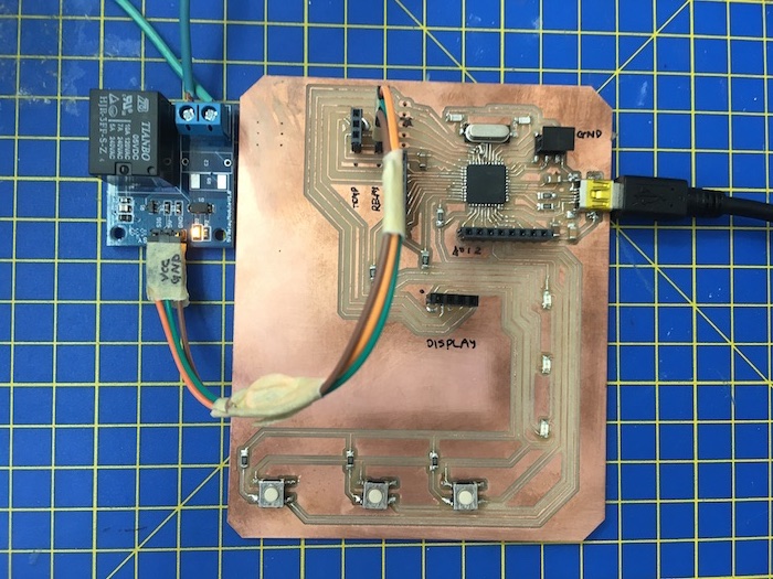
And here's a link to my final project page, where all the design files for this board can be found.
2.0 Group assignment
measure the power consumption of an output device.
Here is a link to our lab's page which includes links to all our group assignments.