Penguino Polargraph
Contents
Version 1: Gondola v1, operating by hand
Version 2: Gondola v2, operating by computer
Version 3: Gondola v3, operating by computer
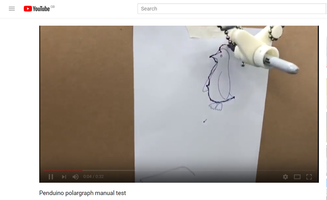
https://www.youtube.com/watch?v=fDa0sfZ-qXU
Andrew:
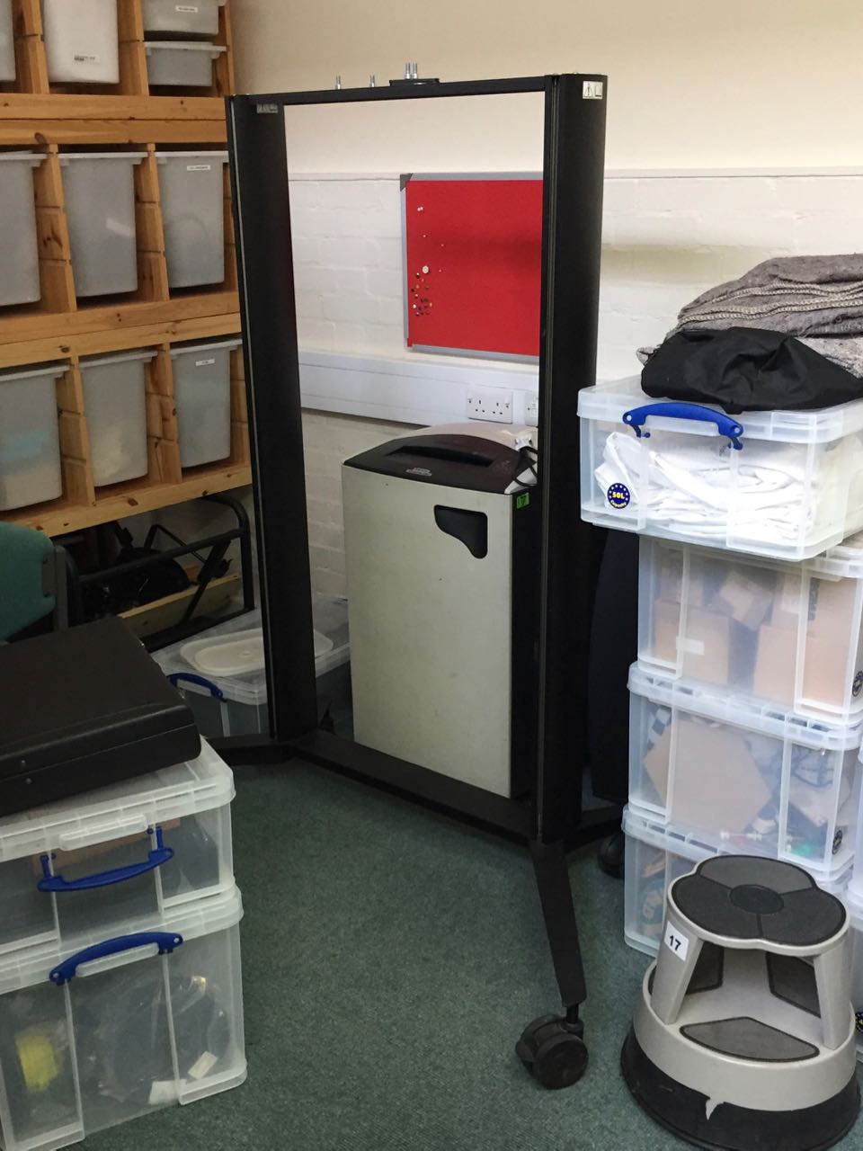
The lab has an existing frame that we’ve decided to use to house our machine. This means we can mount our motors and the workpiece together in a stable and adjustable configuration without having to go and buy materials to make it by hand.
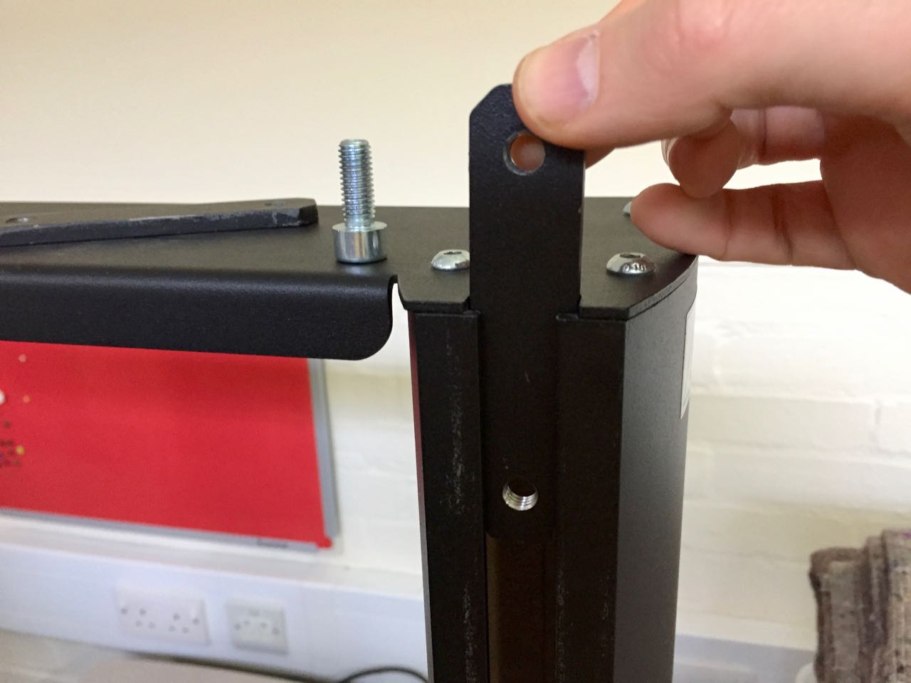
The frame has slots running down each leg, which function in a similar way to 80/20-style aluminium extrusion. It includes two steel backplates with threaded 8mm holes that fit into these slots, and accept a bolt from the front.
We can use these brackets to hold some parts of the assembly, and make more to hold other parts.
Paul:
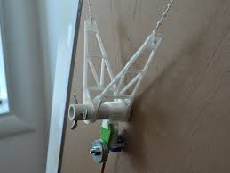
For the attachment to the chain I will need to have rotating pulleys to create a ‘V’ with the point of the V being the pen tip. Adding bearings will allow the angle of attachment to change in accordance with the position of the belt.
It appears weight is important to have the pen sit against the drawing surface rather than swing about or drag along the surface. This seems like a pen/size/system dependant calibration using trial and error.
It is important to make sure the wight is even on all sides of the gondola
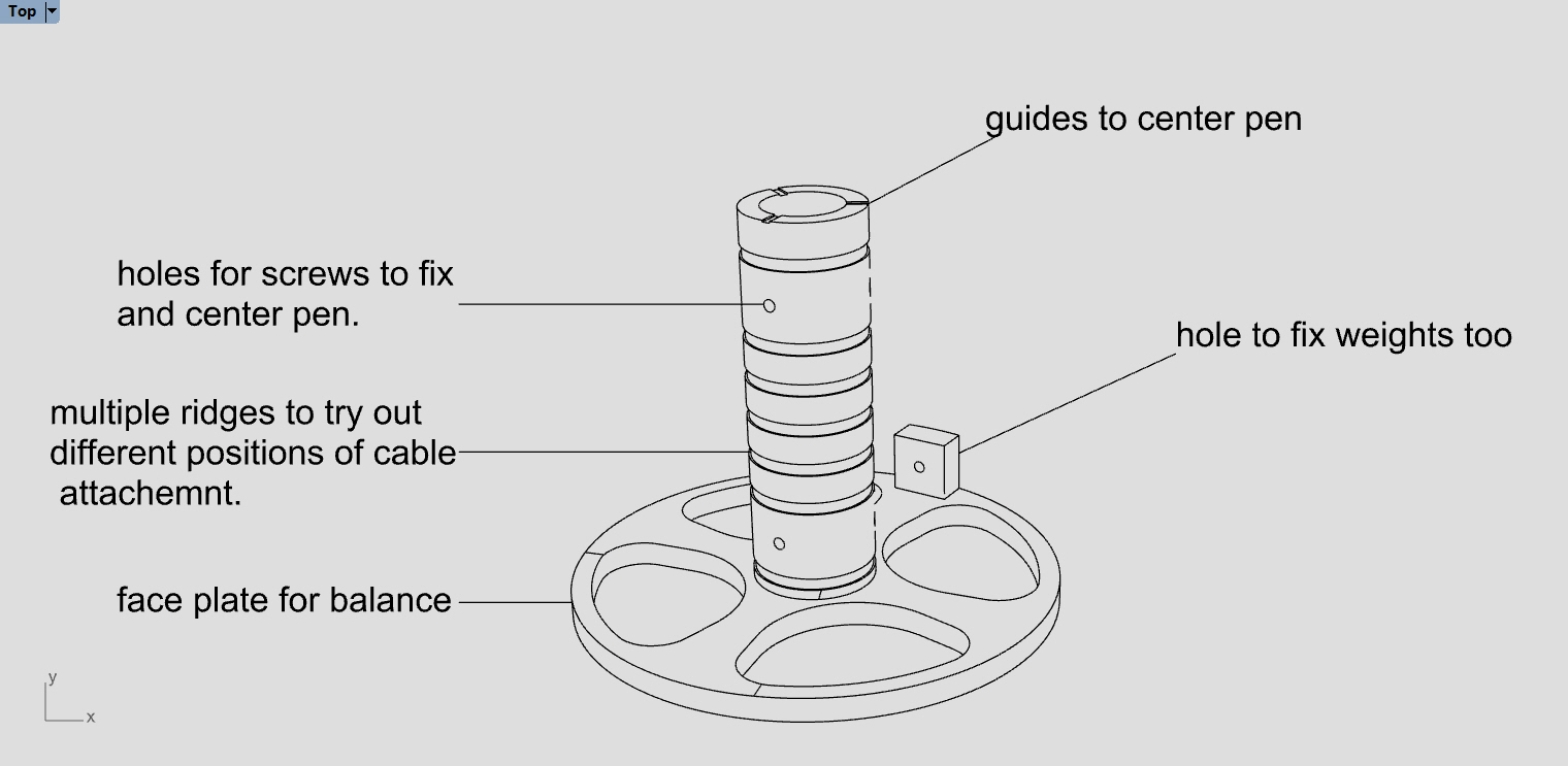
Attaching the pen will require a central hole with three thumb screws to center. This will allow for different pen thicknesses and ease of removal.
The surface will also be important in designing the gondola, vertical or sloping?
Vertical will allow for more accurate drawings over the whole surface, but it will be harder to calibrate and will depend on the sprocket-wall distance
Sloping will could potentially give less accurate drawings at the extremities, but will be much easier to calibrate.
Using 4 cables could allow for greater accuracy and ease when using a vertical surface. It could also allow further development to create a cable printer if turned 90 degrees.
We will likely go with a slightly sloped surface for ease initially.
Looking online there are several different designs that have been used by the pen holder. One aspect that seems common is that almost all of them have some sort of face plate. We can’t find any explanation for this, but we guess it might be to stop the holder loosing balance and falling over.
Most use a bearing to allow smooth adjustment of the gondola position when the lengths of the cable are changed.
Some of the more advanced designs use a servo motor to lift the pen off the drawing surface so it is possible to move across the board without leaving a mark.
A lot of the examples online also have a weight, this is probably something to do with balance and keeping the gondola balanced.
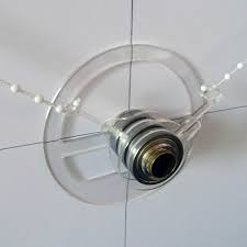
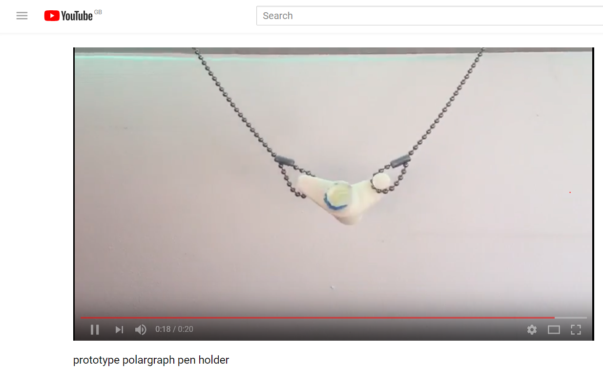
Prototyping
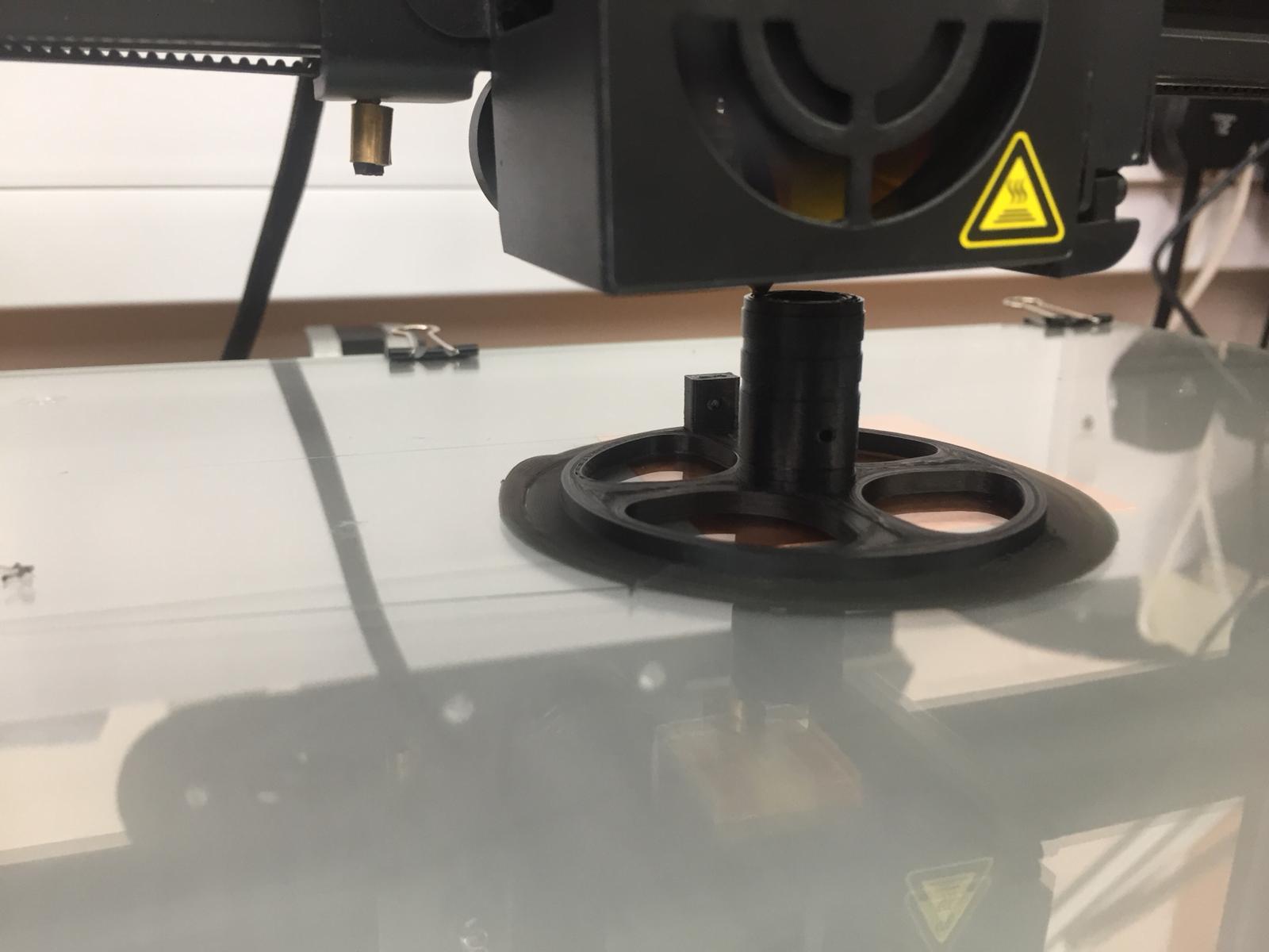
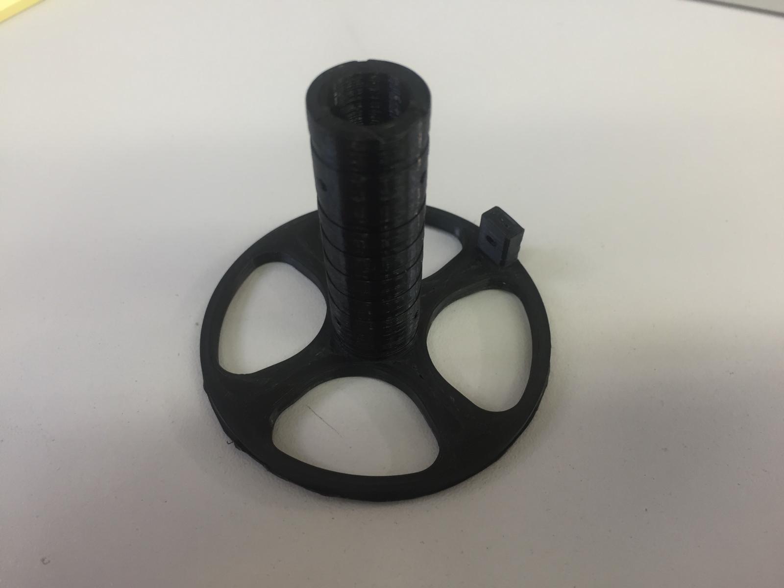
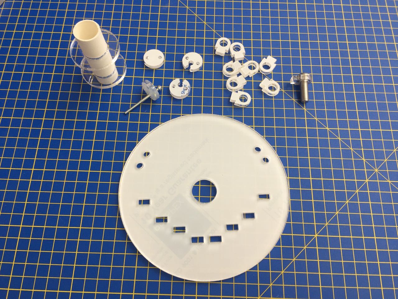
With the above in mind, the initial design was created and 3D printed on a Creality using cura to generate the g-code.
Immediate feedback was that the holder was too small - it would be nice to fit other larger pens in with a larger central bore, which would still allow for smaller pens if we wanted.
We also need to think about how the cables will attach to the gondola in more detail.
Creating the face plate was the most time consuming part of the print, so to prototype faster this will be left out of the next iterations, it will hopefully also show us why it is we actually need one in practice rather than us just guessing.
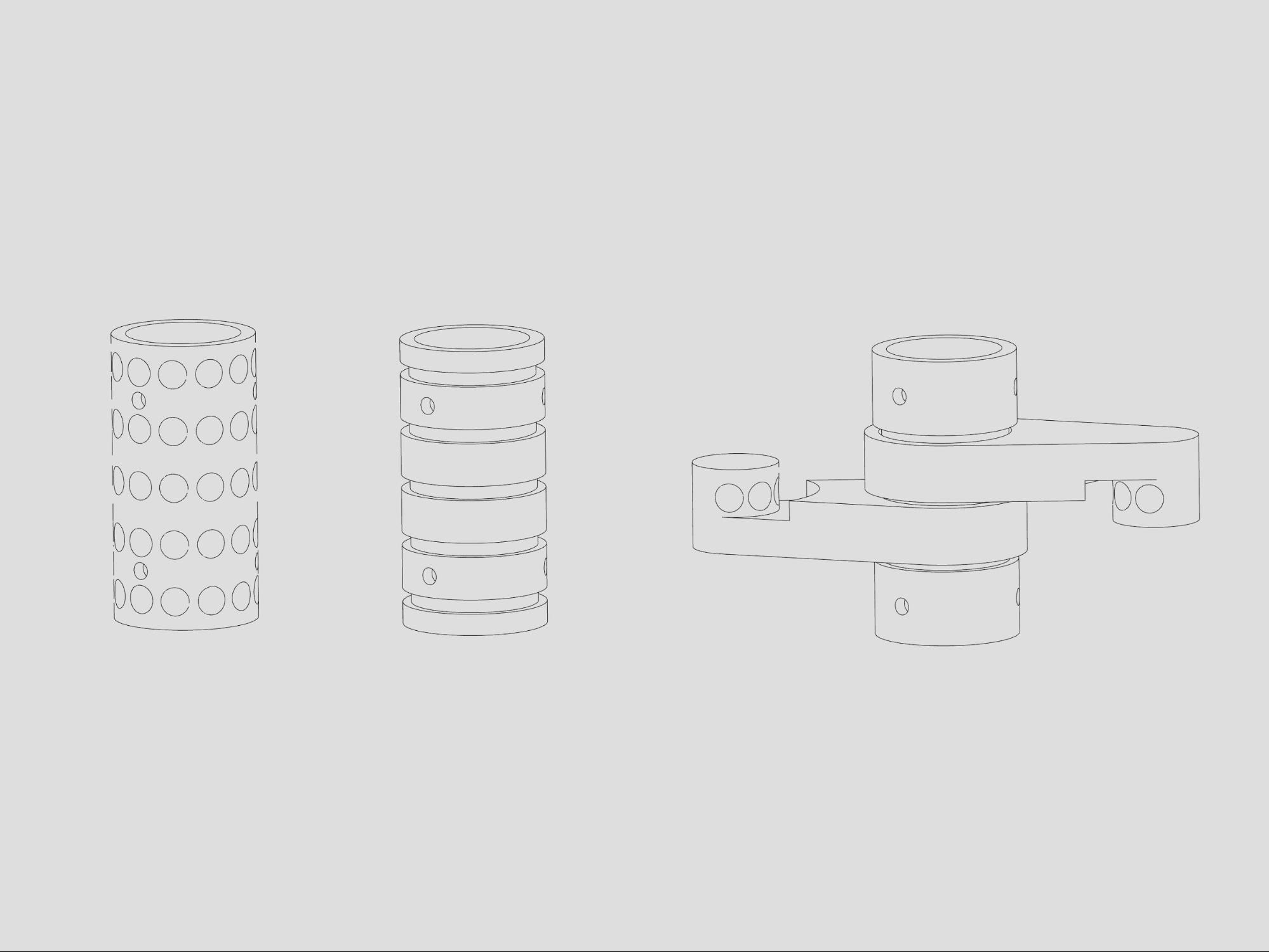
3 further designs were tested;
It was the third design here that proved to be the start. Printed on a robox using automaker (with cura algorithm) for slicing allowed this piece to be printed in one and have moving parts. It was very exciting to remove the supports and slowly reveal the rotation achieved.
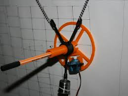
Andrew:
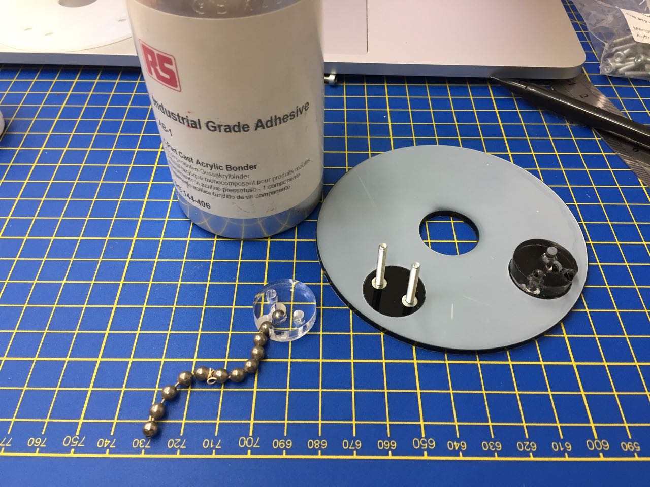
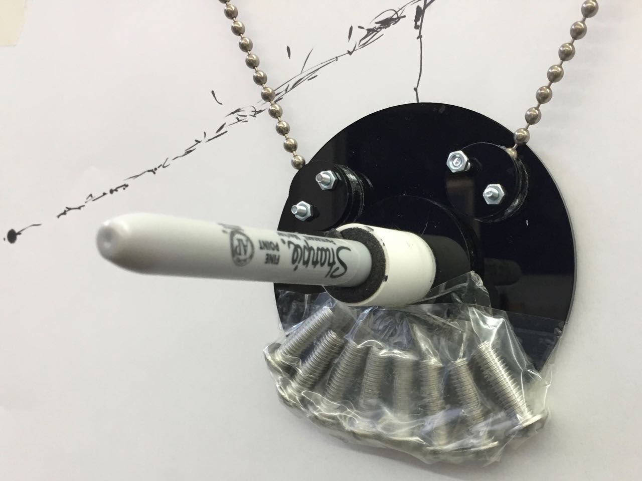
I wanted to improve the gondola by making a verison with a flat acrylic base, to aid smooth movement over the drawing surface. I used some existing PVC pipe (lined with closed cell foam) to hold the pen, and laser-cut the other parts to fit.
I used 1-part cast acrylic bonder to glue the parts together.
We quickly found that the gondola needed more weight to keep the pen stable on the paper, so hacked a quick fix by taping bolts to the acrylic base.
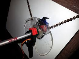
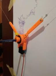
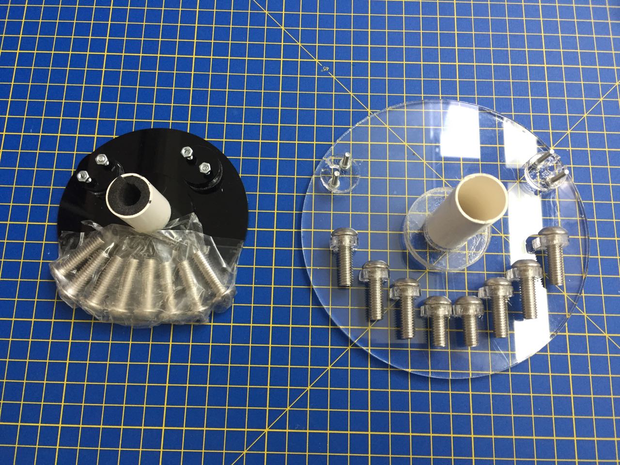
Andrew:
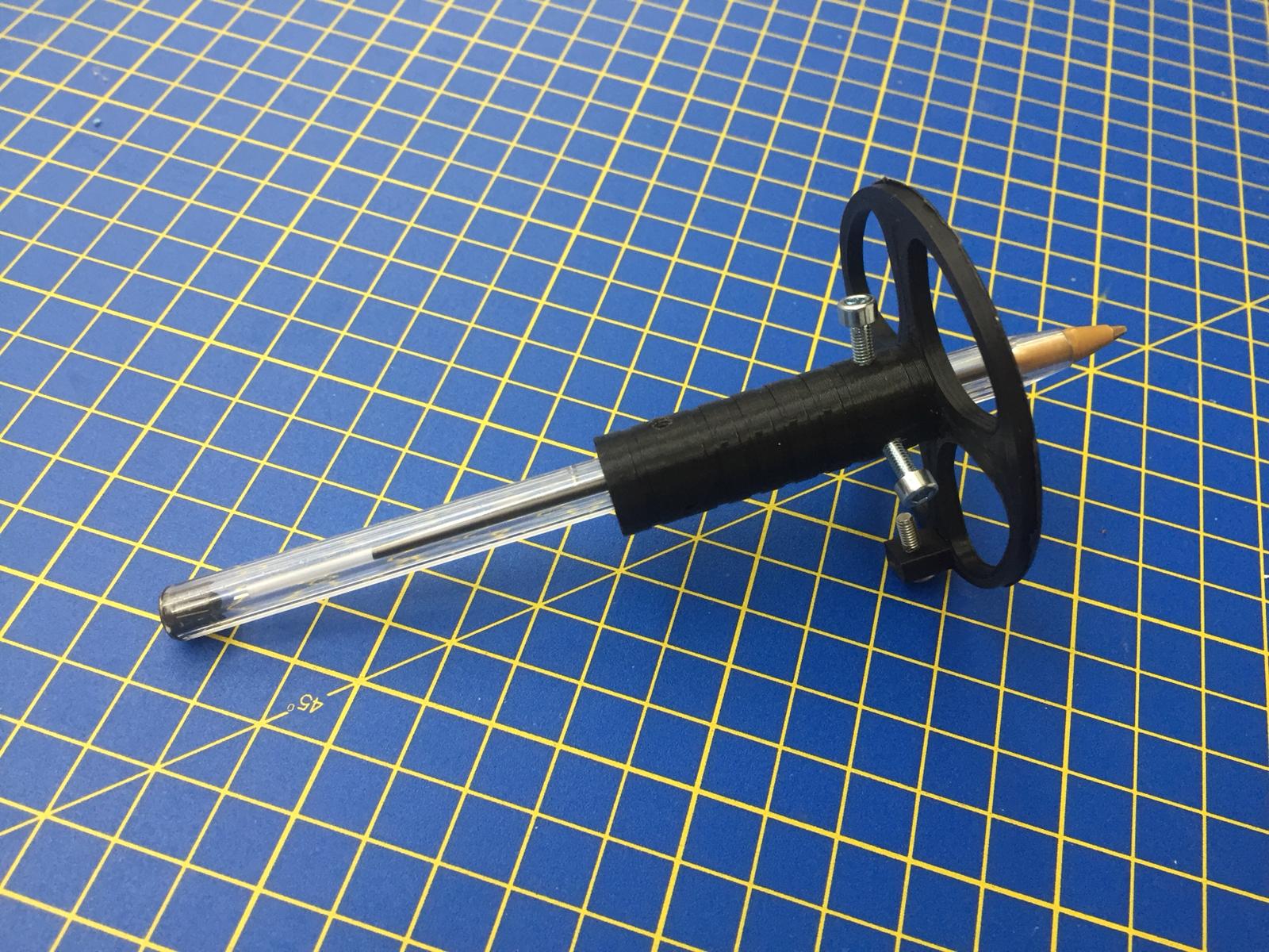
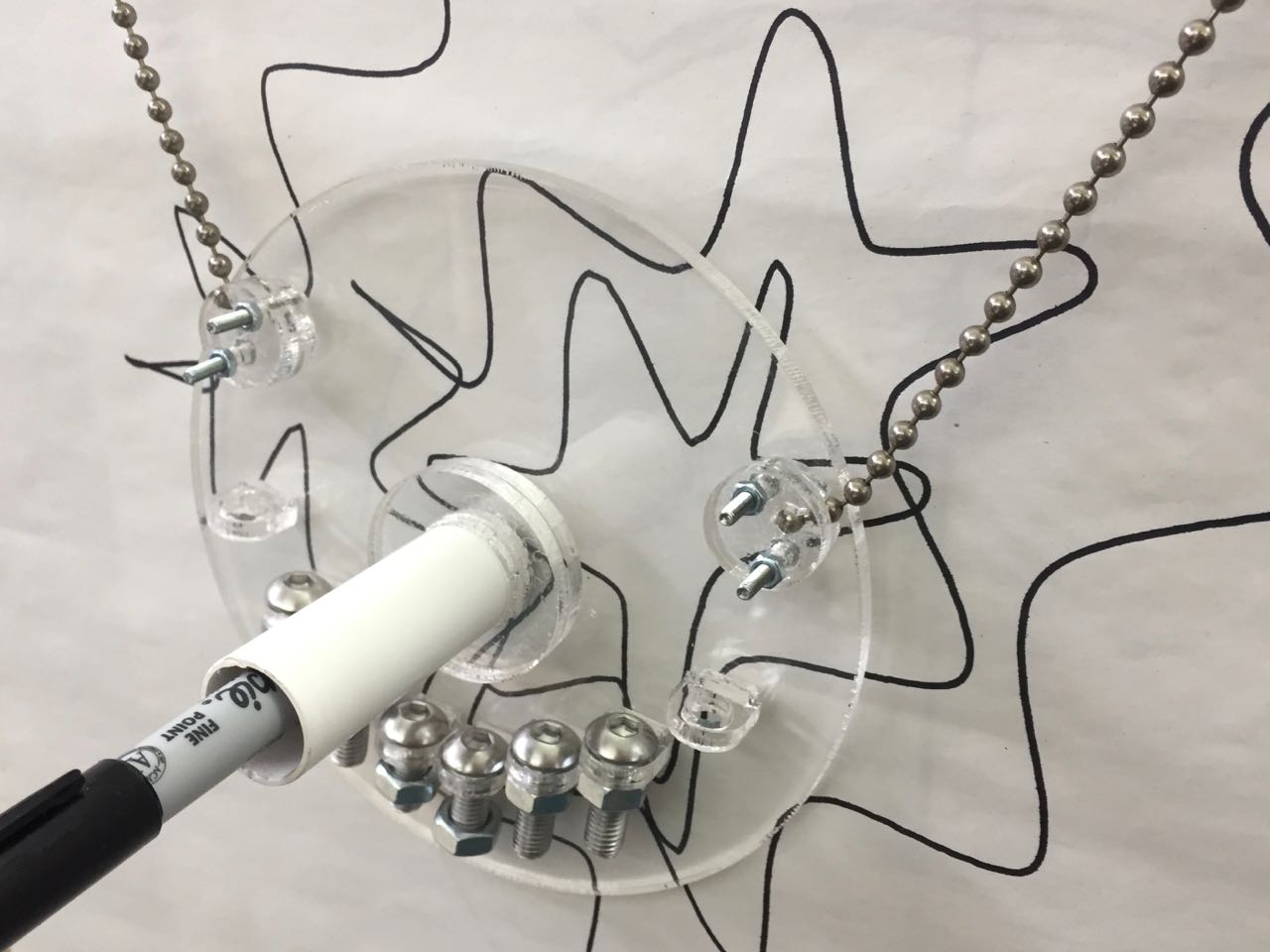
I wasn't happy about the weight hack, so made another version of the gondola that could have bolts attached or removed as needed.
I made all the parts out of clear acrylic, so we could get a better view of the drawing in progress.
Andrew:
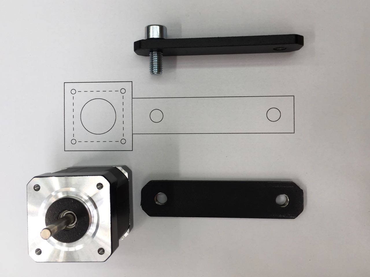
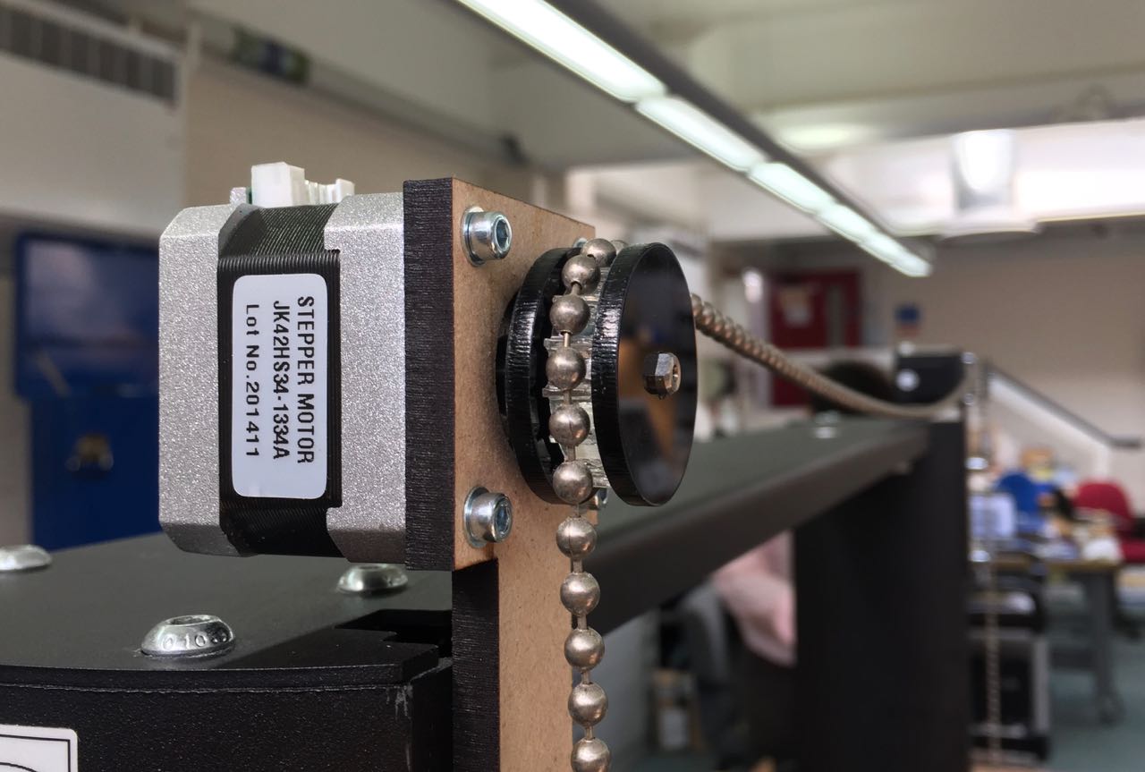
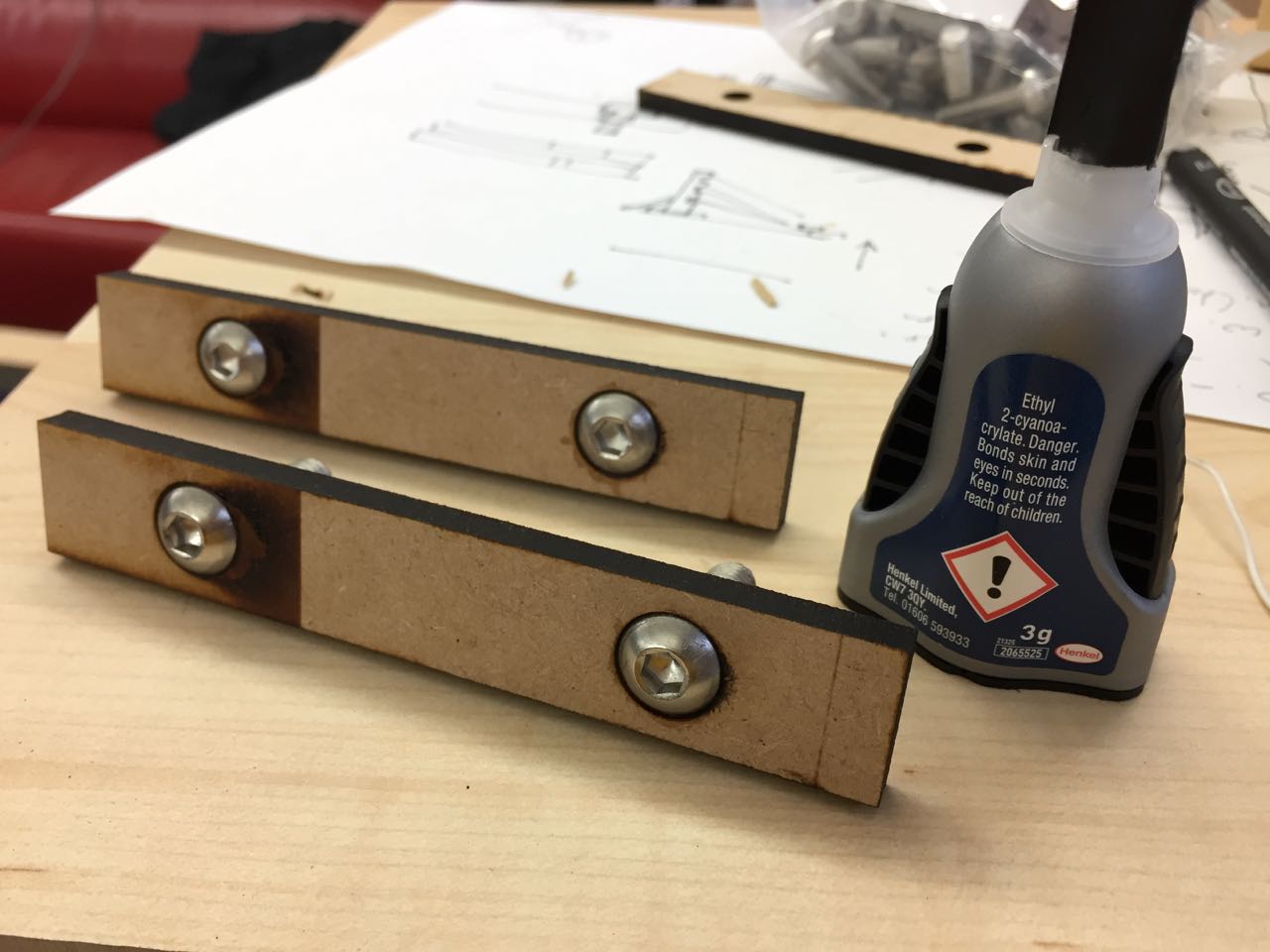
I worked on the mounting system for the motors, and other parts we’re attaching to the frame and also gears to take the chain that moves the gondola.
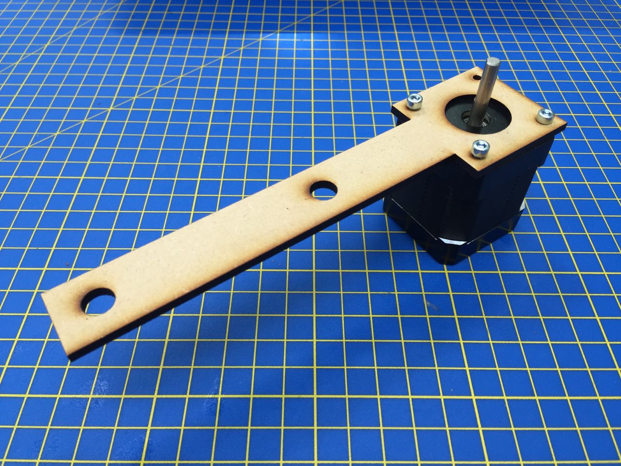
We’re using Nema 17 motors. I wanted to mount these onto brackets, which could be attached to the existing backing plates. By referring to the datasheet, I was able to design a simple bracket in Illustrator with holes correctly sized and spaced for both the motor, and the backing plate.
I cut a test bracket out of 3mm MDF. This worked pretty well, but was too thing for the length of bolts we have in the lab. So for future versions, I used 5mm MDF.
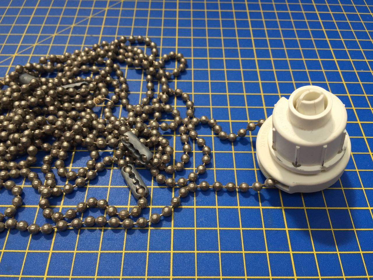
As we don’t have a timing belt, we’re using chain from an old set of blinds. The motors need gears with sprockets to match the dimensions and spacing of the balls on the chain.
By disassembling the blind mechanism, I was able to expose the gear used in the blind, and measure it so I could make my own.
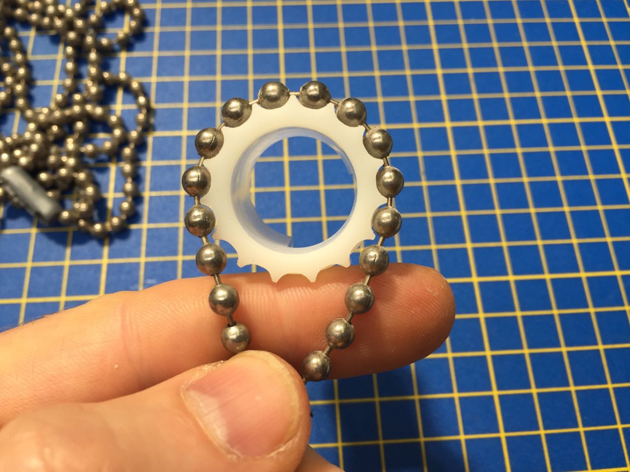
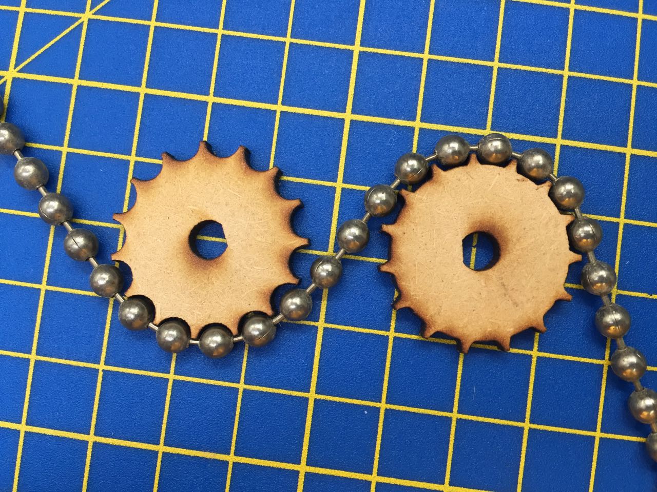
I designed the parts in Illustrator, and started by making two versions, one with sprockets sized exactly to fit the balls, and one with shallower sprockets, more like those on the blind mechanism gear. I cut these in MDF, and tested them out, to find that the latter design worked better.
I made the next version out of 5mm acrylic, and also cut some fences to go on either side of the gear to stop the chain from slipping off.
As the frame only came with two backing plates, we needed to make some more to hold the drawing surface. This frame isn’t designed with user-customisation in mind, unlike 80/20, so it was tricky to make new plates that would work.
The existing plates have threaded holes ot accept an M8 bolt. This draws the backing plate to the front of the frame and pressing it against the frame and the part attached in front. I don’t have the tools or materials to make threaded holes in 5mm steel, so I had to try other ways to create threads.
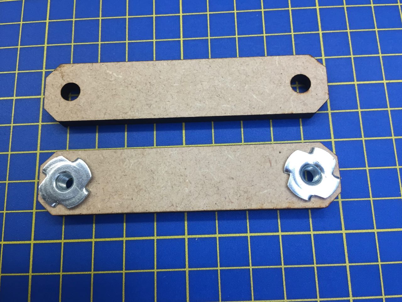
The first attempt was to use locknuts mounted in MDF. This worked, through the MDF tended to delaminate, and the only locknuts we have are M6, which is a little bit too small for this frame.
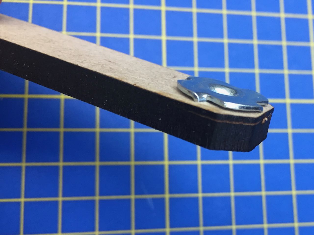
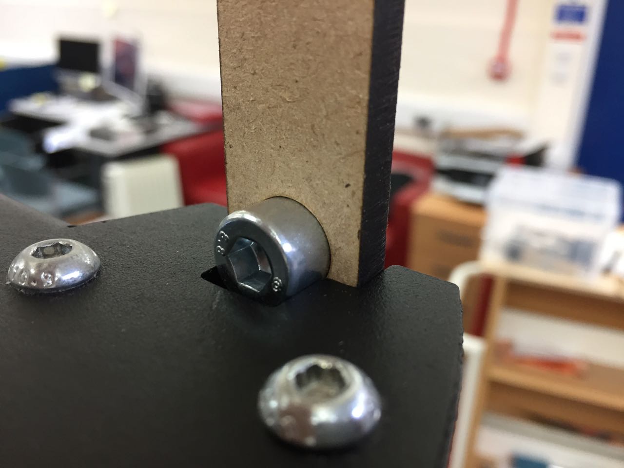
My next approach was to try mounting bolts into the backplate, which could be passed through the frame and holes in the front piece and then pulled together with nuts threaded from the front.
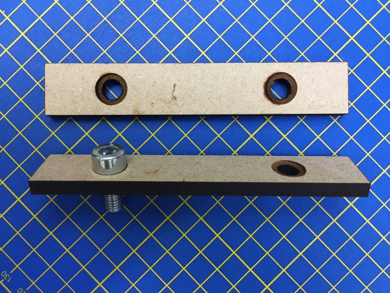
By using the engrave setting on the laser cutter, I was able to create pockets for the bolt heads, so that I could glue them in to stop them turning when nuts are attached. (Ideally you would use hex-headed bolts recessed into hexagonal holes for the best resistance against turning force, but I don’t have any of those to hand.)
However, it turned out these bolt heads were too large to fit into the groove. So next, I tried using dome-headed bolts. The fitted better into the frame, and I was able to secure a heavy steel shelf onto these backing plates.
Andrew:
We figured we needed a cool name for our machine, and came up with Penguino, playing on the Arduino name, and the ‘polar’ in polargraph. I also like the idea of using an iceberg in the artwork to reflect the deep V shape characteristic of a polargraph plotter. I came up with something in Illustrator. This artwork uses Creative Commons licensed elements from the Noun Project:
Andrew:
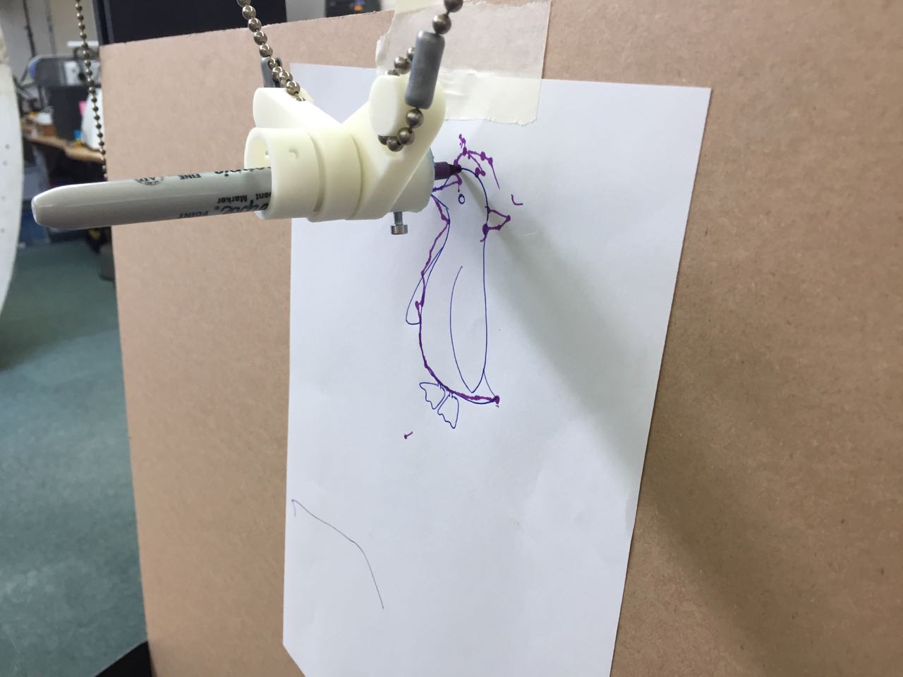
Once we brought all the pieces together in the lab they worked surprisingly well. We had michael draw a frustratingly small penguin for us, but we were actually quite amazed by how good we were at tracing (we were expecting nothing as close as this) by moving the motors by hand.
It showed that some extra weight is needed to overcome the drag force of the pen and the faceplate would have helped to keep the pen perpendicular to the drawing surface. Over all we are pretty happy.
Paul
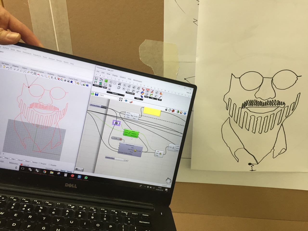
I have experience using grasshopper to generate gcode and found it a very effective way to read polyline geometry.
The first task for this was to understand the geometry and variables of the machine, then to calculate the cable length with the gondola at a certain point.
To do this I used the website here:
https://www.marginallyclever.com/2012/02/drawbot-overview/
Once our machine geometry could be read and any point along the curve it was a case of reading the values at subsequent points and finding the difference from the previous value. Once I had the difference between each point on a curve, I cumulatively added these so I could use absolute coordinates on my machine and add the relevant ‘G’, ‘X’, ‘Y’, ‘F’ value.
We will be using a program called Marlin which has a specific ‘Flavour’ of Gcode. Some of the commands we have looked at are:
http://marlinfw.org/meta/gcode/
(M280 - set servo position absolute. P: servo index, S: angle or microseconds
Angle should be from 0 to 180 or microseconds from 1000 to 2000. 1500ms or 90 degrees is the center position.)
We only ended up using G1, an example set of code being;
G1 X18.07 Y27.08 F300
G1 X18.96 Y28.43 F300
G1 X19.85 Y29.79 F300
‘G1’ indicating a linear movement ensuring both X and Y values are completed at the same time using linear interpolation.
‘X’ and ‘Y’ indicating the cartesian coordinates (or however your machine is set up)
And ‘F’ indicating the speed of movement. Our range was from 0 to 3000.
We would like to add a servo that would lift our pen off the drawing surface and enable us to draw with less limitations, but we were not able to get the M280 command to work.
Marlin
http://solidutopia.com/marlin-firmware-user-guide-basic/
I uploaded the Marlin firmware onto the Arduino Mega which can all be edited and uploaded using the Arduino IDE. The RAMPS and Marlin firmware are a bit overkill for our purposes, as they are designed for 3D printers that could have multiple extruders. We knew we were going to use two NEMA 17 stepper motors to rotate our bobbins based on their range of motion and accuracy. The hardware/firmware combination is very comprehensive and powerful hardware/firmware combination which also means there is a lot of documentation.
One of the main values we had to change in the configuration.h file was the ‘steps per unit’. This will change depending on the size of the pulley and belt we use. I can get this value from my grasshopper script. I initially forgot about microstepping (limited by the driver we use - pololu a4988 gives 1/16th microstepping), but once factored in we got the correct value and the machine working. Using the link below it was good to check my calculations;
https://www.matterhackers.com/news/3d-printer-firmware-settings-stepper-motor-configuration
At the very bottom of this page there is a super useful link to calculator developed by Josef Prusa for calculating the movement setting values for both threaded rod and belt driven axis.
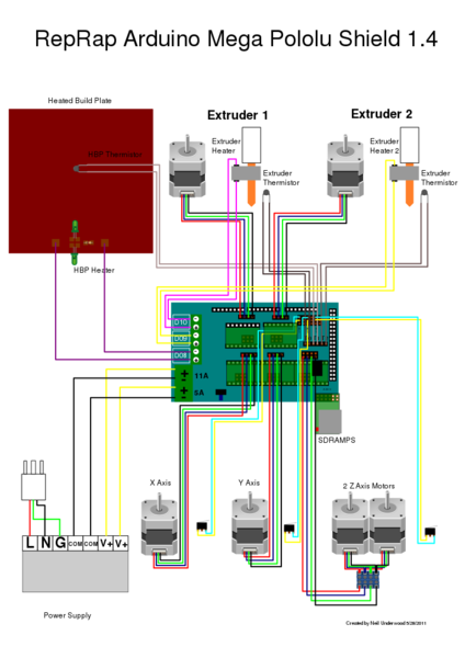
RAMPS 1.4
This board sits atop our Arduino Mega. It is a shield that enables us to easily add our stepper motor drivers (we used Pololu A4988) and connect our two NEMA 17 steppers. To connect a servo we need to switch a jumper to power the servo circuits. These are near the 12V power input. A basic setup can be seen in the image below.
https://www.v1engineering.com/assembly/ramps-wiring/
We removed the barrel connector from the Mega as it seemed to be getting in the way of the RAMPS fitting properly on the Mega board.
We were having issues at first using drv8825 drivers rather than the a4988 drivers. This gives us a lot greater control allowing 1/32 steps!
Unfortunately there were some issues reported with some makes of motors, I didn’t get to the bottom of this, but when we tried the a4988, we had no issues at all.
http://www.instructables.com/id/Installing-and-Configuring-DRV8825-Stepper-Drivers/
Interface aka Pronterface.
A standard and commonly used interface for the Marlin/Ramps combo is a program called Pronterface. It is very simple to use and easily connects the the Mega setup when connected.
The wiki is here
http://reprap.org/wiki/Pronterface , but you can download a package so you don't have to worry about installing the individual programs to run it.
http://kliment.kapsi.fi/printrun/.
The grasshopper code creates and saves out the gcode to a .gcode file. Uing pronter face it is just a case of opening the file and clicking print.
Paul:
The limitations of our machine meant we could only draw a single continuous line. We created a few test files to measure accuracy, repeatability and if any accumulated errors were in our file, but all the drawings were pretty simple.
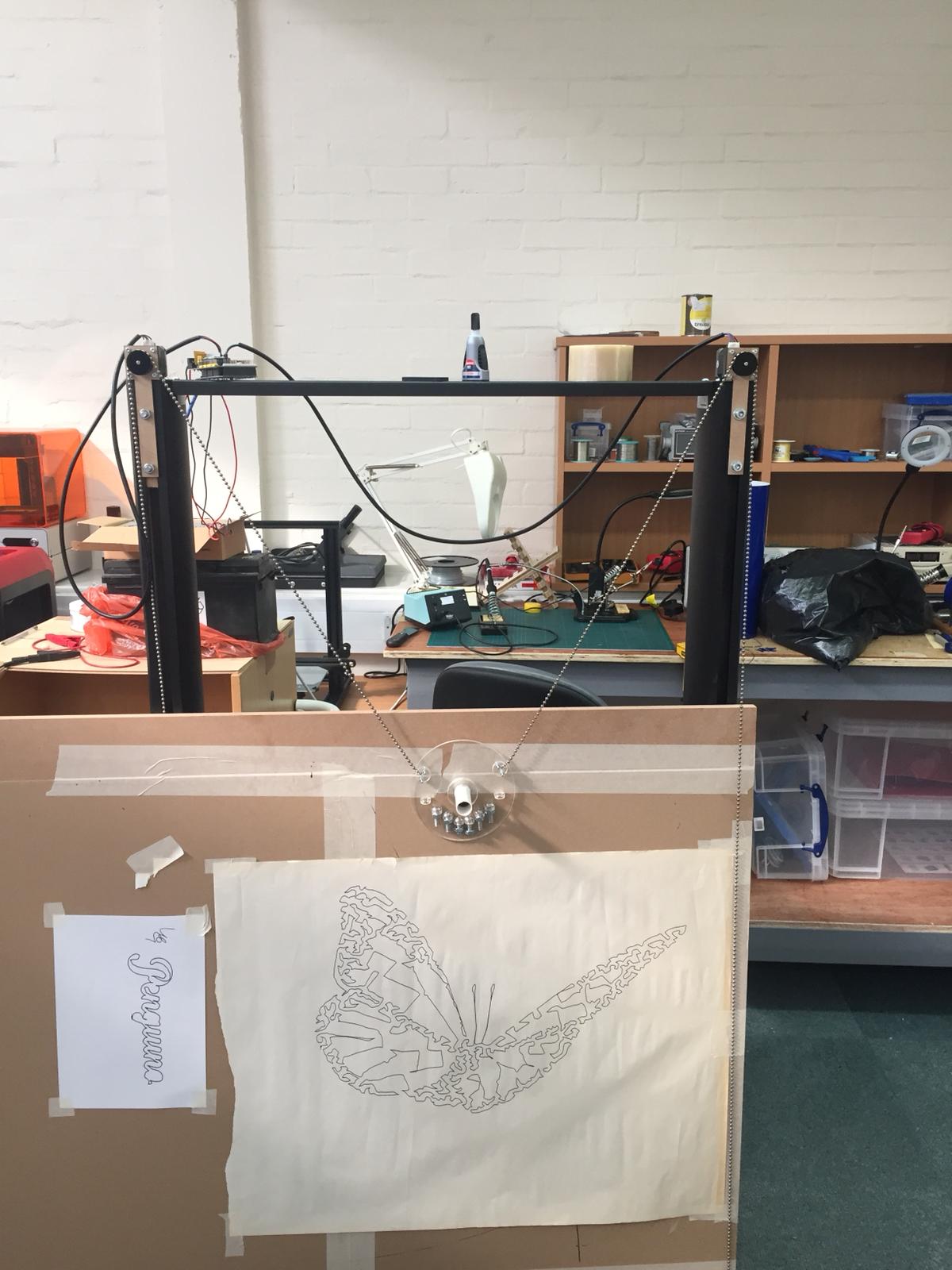
We found a program called Stipple gen 2.
https://github.com/evil-mad/stipplegen/releases/tag/v2.31
This program takes an image, applies points based on grayscale, from this a voronoi diagram is created which then creates a new set of points and subsequent iterations refine the distribution.
From this it is possible within stipple gen to run a Tradesperson shortest path or ‘TSP’ algorithm which creates a single line across all the points (in theory in the shortest path) This is how we created the butterfly picture below.
We’re not the first people to build a polargraph. Here are some of the existing projects we drew from: