Computer-Controlled Machining
Peter's, Jimena's, Lukas and Tanja's Part:
Task:
- Test runout, alignment, speeds, feeds, and tool-paths for your machine (group project)
For this assignment we were in the FabLab Kamp-Lintfort and used the CNC machine elsign EasyWorker Master pro 2513. The instructor of Kamp-Lintfort Daniele Ingrassia explained us, how to use the CNC machine.
CNC elsign EasyWorker Master pro 2513
Design Rules | Preparing the export file in Rhino
resumed the check rules Daniele told us in Kamp-Lintfort:
- No overlapped lines: check them in Rhino: go to ->Select and then ->Select Duplicated Curves. Rhino shows the overlapped lines yellow. Now you can delete them.
- No loose lines: you can join loose lines in Rhino by using the command “Join” and then click the lines you need. The lines have to build a closed curve!
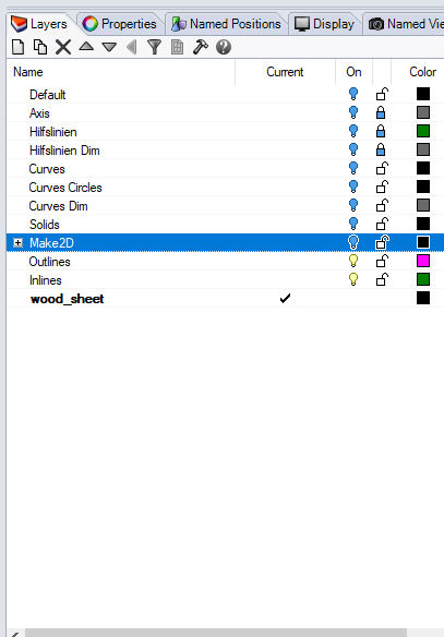
After that,We would move the closed curve to another layer. - We added 3 layer for the export file: Outlines, Inlines and wood_sheet. If you are going to engrave, you have to add one more layer. We asked Daniele (instructor) how many layers we needed for the CNC software. We assigned each layer a different color.
- If you import a DXF file from Fusion360, you have to prove that there are no tiny loose lines or points in your file. Sometimes you don’t see them on the screen. After moving the closed curves you to need to another layers, click Control+A and Delete.
- The size oh the wood sheet you are drawing has to correspond the real size of the wood sheet you are going to mill. Use a different layer in Rhino for example “wood_sheet”.
- When you are placing the pieces on the wood sheet in Rhino you have to check:
→ the tolerance between the paths in one piece: 10mm and
→ the clearance between the pieces: 10 mm
- Last check: Turn on all layers, Explode all closed curves and then join them again. If Rhino shows in the command lines that all curves could be closed and there are no open curves, you can start exporting the DXF files.
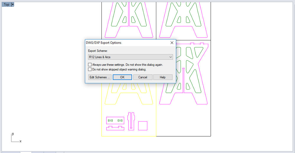
- Daniele told me to use the DXF Export Options: R12 Lines and Arcs. Each wood sheet with its pieces will be exported separately.
Kerf Test
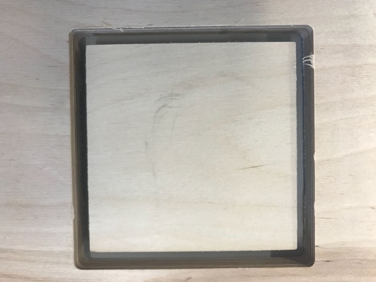
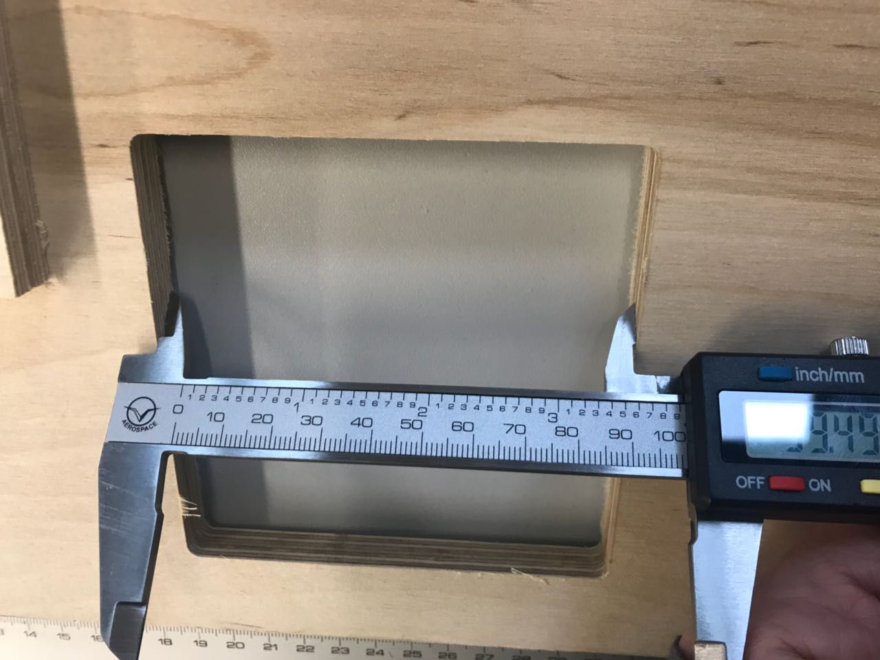
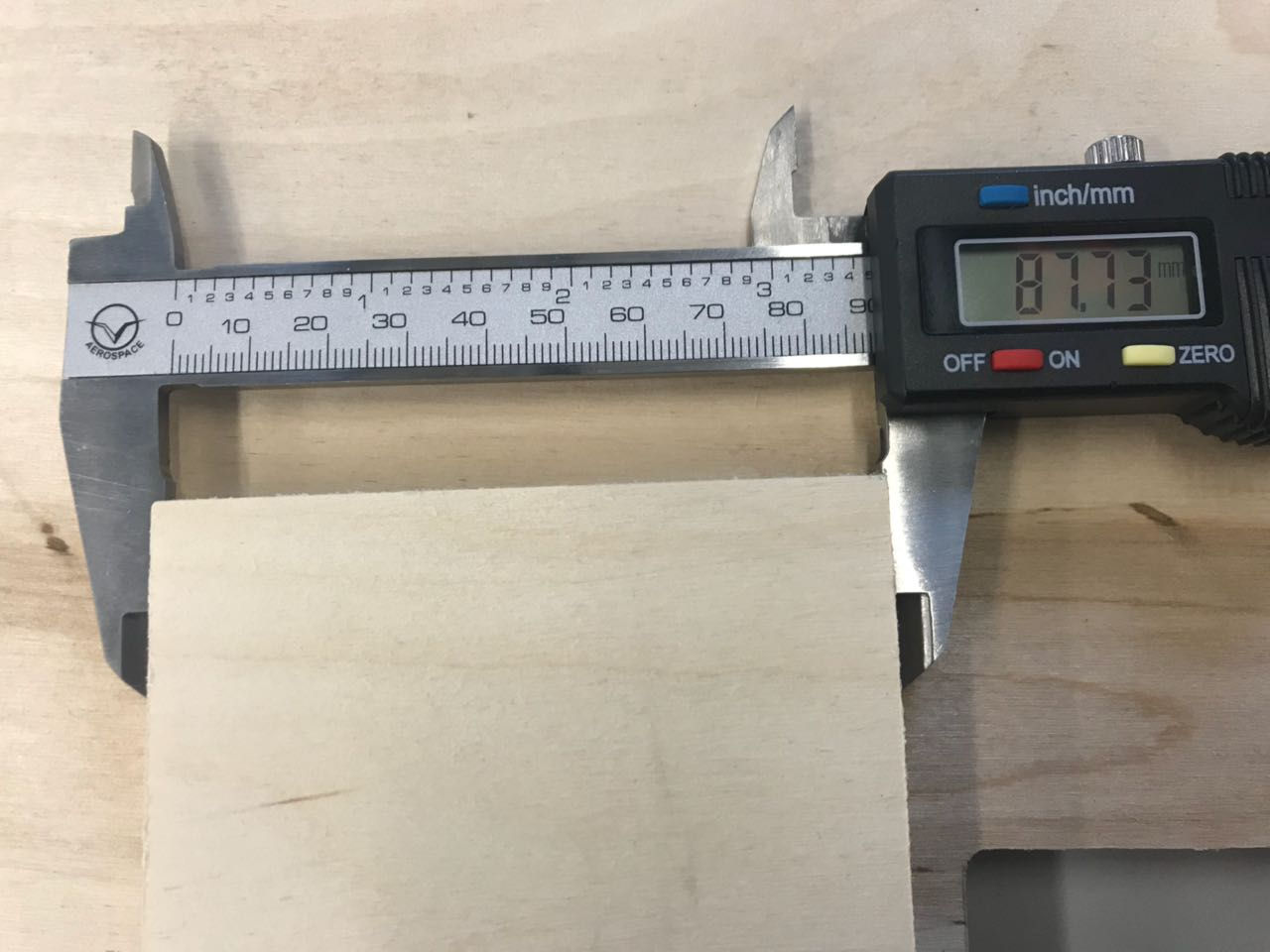
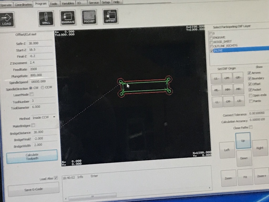
I tested the kerf width for the end-mill we used (diameter 6mm) and milled a 100 x 100 mm square as an Inline. The software calculates the offset depending on the diameter of the end-mill you are using. The CNC cut a 99.49mm square with round corners, because we chose Inline-Offset. The size of the square is 87.73x 87.73mm. You can choose the offset for Inlines or Outlines.
T-BONE JOINTS Test
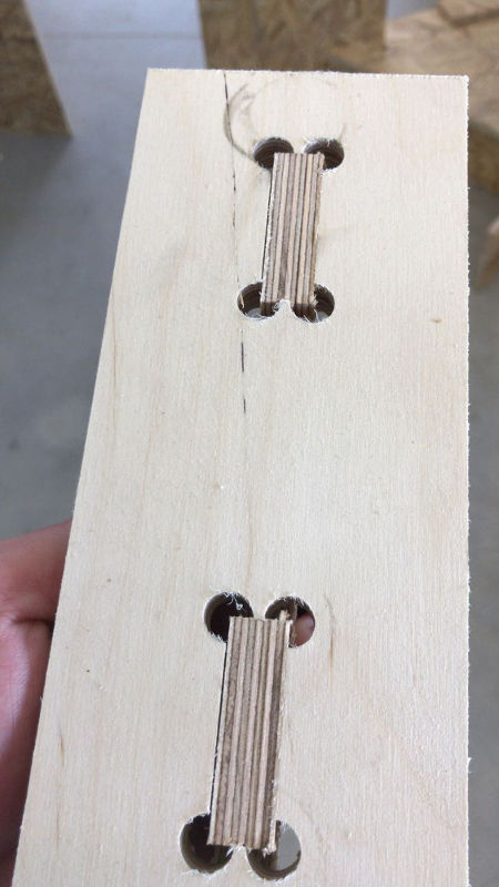
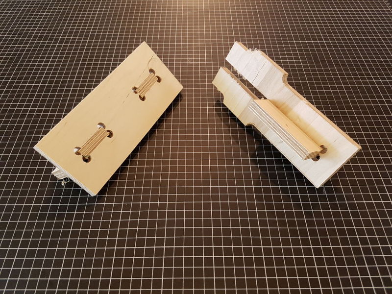
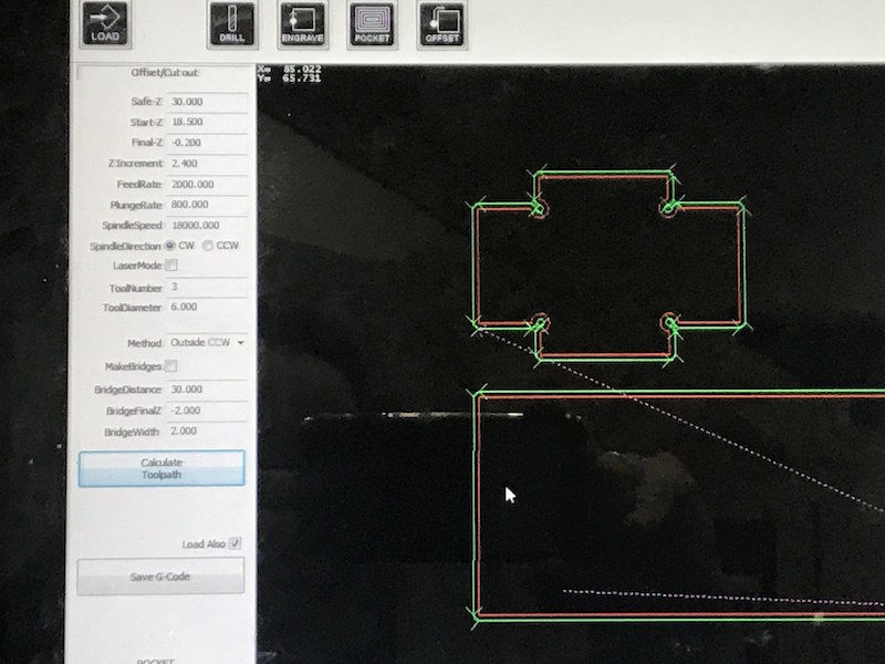
I also tested the t-bones joints for the coffee table. We used a laminated wood sheet with a thickness of 12 mm. For the 6 mm end-mill We changed the radius of the t-bone joints from 4mm to 5mm. The radius can’t be smaller than R=5mm otherwise the CNC cannot mill the pockets of the joints.
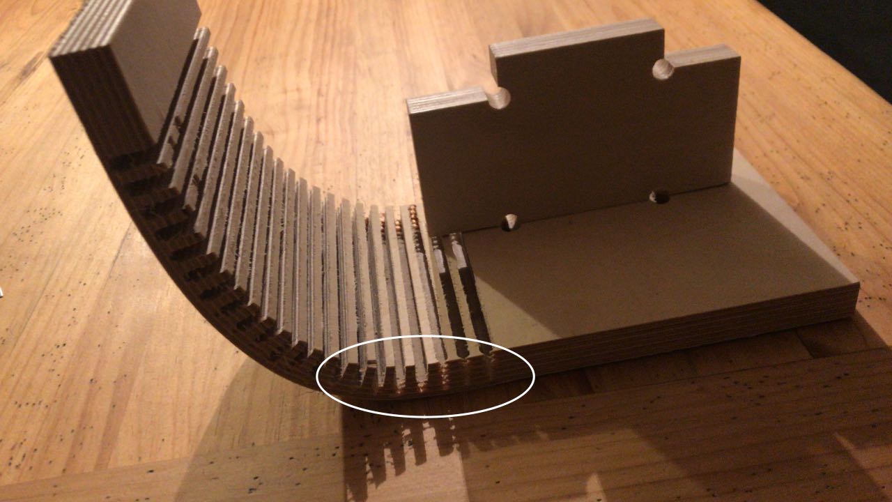
Kurve Bending Test
We made some tests with kurve banding because We like this technic of wood preparation very much. We was inspired through the project of my colleague Aleksandra Konopek from her "Makes Something Big" week in 2017.
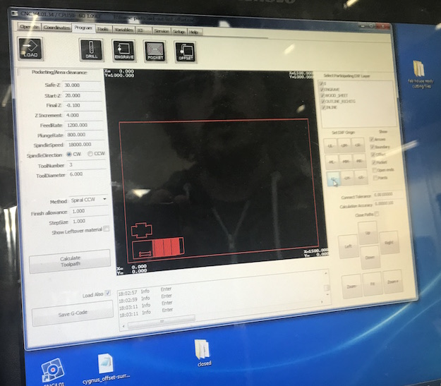
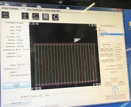
We uploaded following Rhino file to the controller of the Easy Maker Pro:
The settings below we used for Kurve Bend Milling:
Engrave settings
| Safe-Z | 30 |
| Start-Z | 20 |
| Final-Z | 17 mm (no cut trough the material!!) |
| Z Increment | 4 |
| FeedRate | 1200 mm/min |
| PlungeRate | 800 mm/min |
| SpindleSpeed | 18000.000 rpm |
| SpindleDirection | CW (clockwise) |
| ToolNumber | 3 |
| Laser Mode | OFF |
| Time total | 10:00 min |
| ToolDiameter | 6.000 (mm) |
| Method | Inside Spiral CCW (for Engraving) |
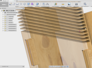
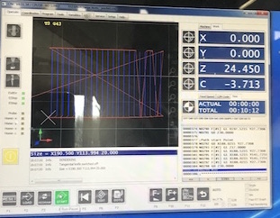
The next images show the loaded test-file with kurve bending, one T-Bone connector and the hole after calculating the tool-path.
Following images show the increments of the tool-path for the T-Bone, calculated tool-path for the kurve bending and the progress of the milling process.
The following short movies show fast forward milling process of kurve bending.
For the kurve bending we have chosen the "Engraving" cutting option because the cut should not go through.
After milling of the test part was finished, we assembled the t-bone connector with the hole with a several powerful hammer strokes. The connection was very stable.
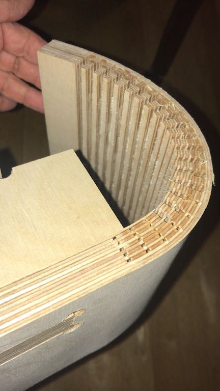
As the test cut was finished we burnished it at several places and tried to bend it. We worked very good. Later we make some tests using hot water and sprinkled the test part with it, bend it and pressed it with some books. We left it get dry during one night.
The next day it was dry and stayed in form as wished (90 deg).
The following images show the dimensions measurements of the t-bone and bend ranges after milling.
Downloads
| CNC Tests(zip) | Download |
Daniel's and Christoph's Part:
Daniel's Memories from 2016:
I encountered these problems in 2016. After finishing my make-something-big part, the mill got a new post-processor with a complete new toolchain!
The CAM program recognized all the paths from the 2D sheet out of Solidworks correctly, but the CAM processor is a real pain. It only reads old R12 DXF files. The CAM processor needs per machining step a single layer in the DXF file, which was a real problem for me in SolidWorks. I made the model the days before and travelled to Kamp-Lintfort to get the last information to create a DXF the right way.
The first sheet made no problems. There was just outline milling. This sheet was a single layer and the program recognized everything correctly. But my second sheet made some real problems. I was not able to convert my inner cuts to a second layer in SolidWorks. This took my 2 hours in SolidWorks without any success. Karsten told me that he used Adobe Illustrator some weeks ago and it worked without any problem. I tried this - and we both stood weird looking in front of my MacBook.
I don't know why even this was not the solution. Illustrator was not able to export the DXF correctly. After this,Adriana helped me a lot with Rhino to solve this toolchain f**kup. She was able to change the lines which must be added to another layer. After this, I was able to mill my boards mid at night.
Daniel & Christoph Testing With the Big Mill, 2018
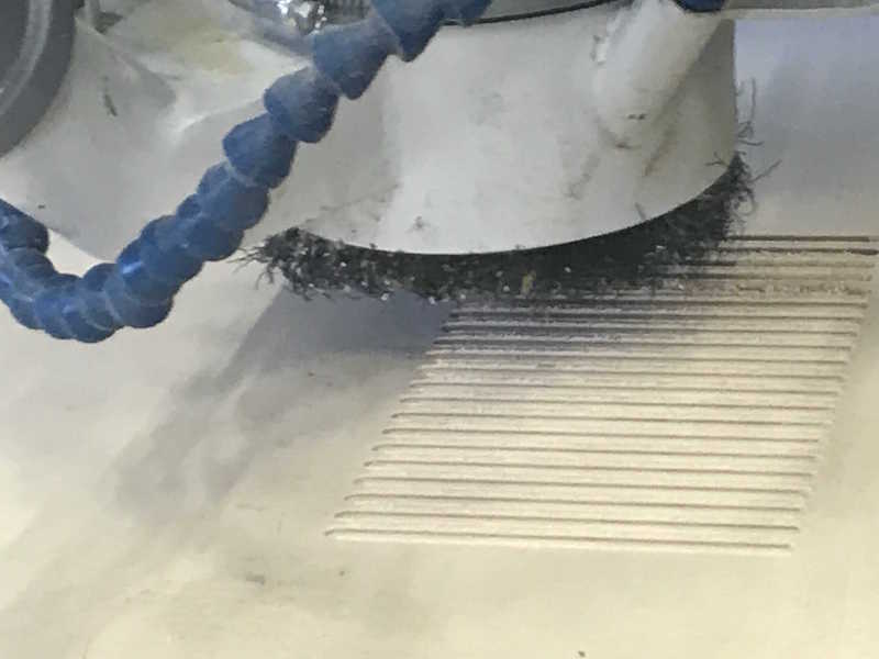
Since there is no other usable mill available here, we used the large 4-axis CNC mill at the Technical Center for Thermal and Mechanical Process Engineering, where Daniel works. We used a 90° 50mm face-mill for our tests:
So, we clamped a 40x40 mm steel bar in the vise as sacrificial object to test:
We made different facing operations with different feed rates to compare the resulting quality.
After each run, everything is swamped in coolant, so... Wait for the rest to drip from the machine head, then swipe it.
The settings for the first run were the recommend from the manufacturer with 0.15 mm/tooth and 2040 rpm:
The first run. Nice and flawless surface.
The settings for the second run were a half of the recommend from the manufacturer with 0.075 mm/tooth and 2040 rpm:
The second run has the same flawless - but not better - surface than the first one.
The settings for the third run were a quarter of the recommend from the manufacturer with 0.037 mm/tooth and 2040 rpm:
The third run has the same flawless surface like the runs before.
The settings for the forth run were a 1/8th of the recommend from the manufacturer with 0.018 mm/tooth and 2040 rpm:
The forth run was interesting - somewhere between the third and forth run is the limit, where the tool turns to fast for it's feed. The surface was still flawless, but started to get some optical issues.
This was a nice comparison to see the impact of a false feed rate. If the feed is too slow, extra heat will be transformed by every unintentional rotation - which means contact - with the material. As the chip volume is too low - through the lower chip load by the lower feed rate - to dissipate all the heat, plus the extra heat, the optical and mechanical quality drops through the heat.
Why don't you push your machine and the tools to the limits to do a real runout?
This is a +$100k tool, with really expensive milling tools (the 90° facing mill costs ~$700) for prototyping. The manufacturer of the tools is a very reliable and esteemed company with a department for testing their tools upon their limits to mill the parts as fast and efficient as possible for mass production. They publish the limits of their tools and not the conservative settings.
