Computer-controlled cutting
Task:
- make laser cutter test parts, varying slot dimensions using parametric functions, testing your laser kerf and cutting settings (group project)
Lukas Part:
In this assignment I like to start with a few test with our laser cutter (Epilog Zing 24) with 50W. After I know the best settings I'd like to design my own press-fit system.
Cutting setting
I decided to start with some test with the cutter-settings. We use our lasercuter with the Visicut software so I took a look at the setting possibilities. I found some propositions for different materials and thicknesses. But for my preferred material of multiplex-wood with the thickness of 3,4mm there weren't any given options so i had to test by my own. I designed the matrix below with Inkscape and tested it with different combinations of power and speed of the laser.
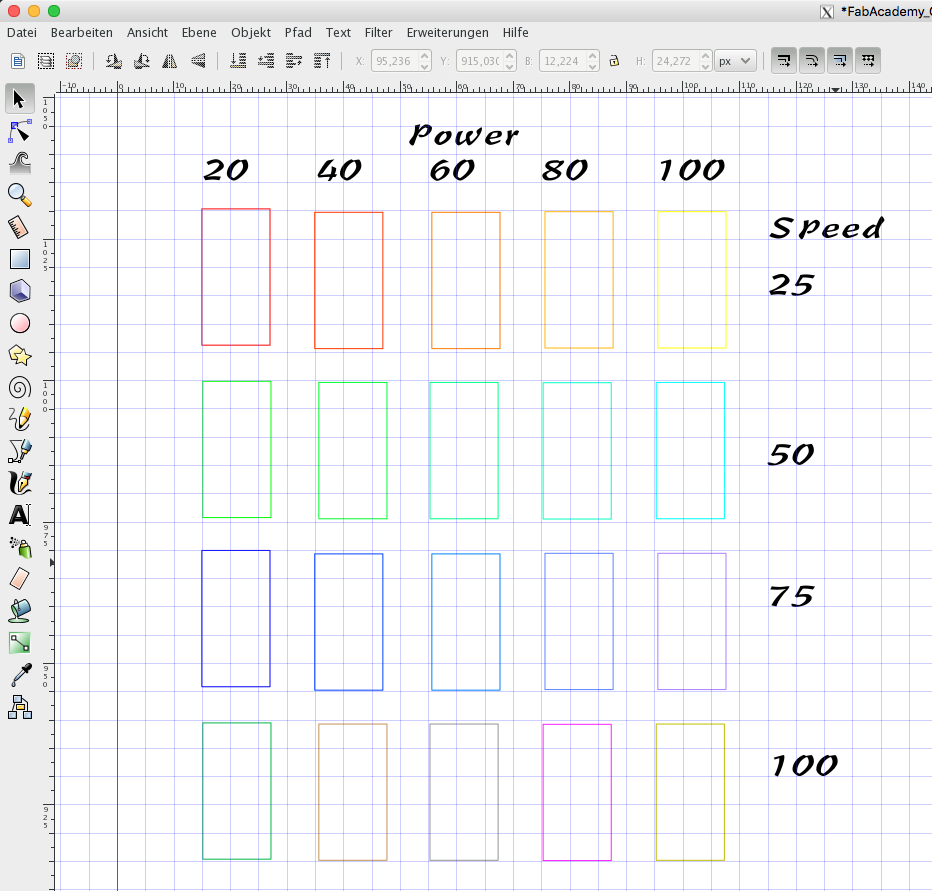
As you see I tested the range of power from 20 to 100 percent. Also I tested the speed from 25 to 100 percent. So i got 20 different combinations of settings. To differ the single test rectangles i used different colors. So I could choose different settings to each rectangle in Visicut. See here the result:
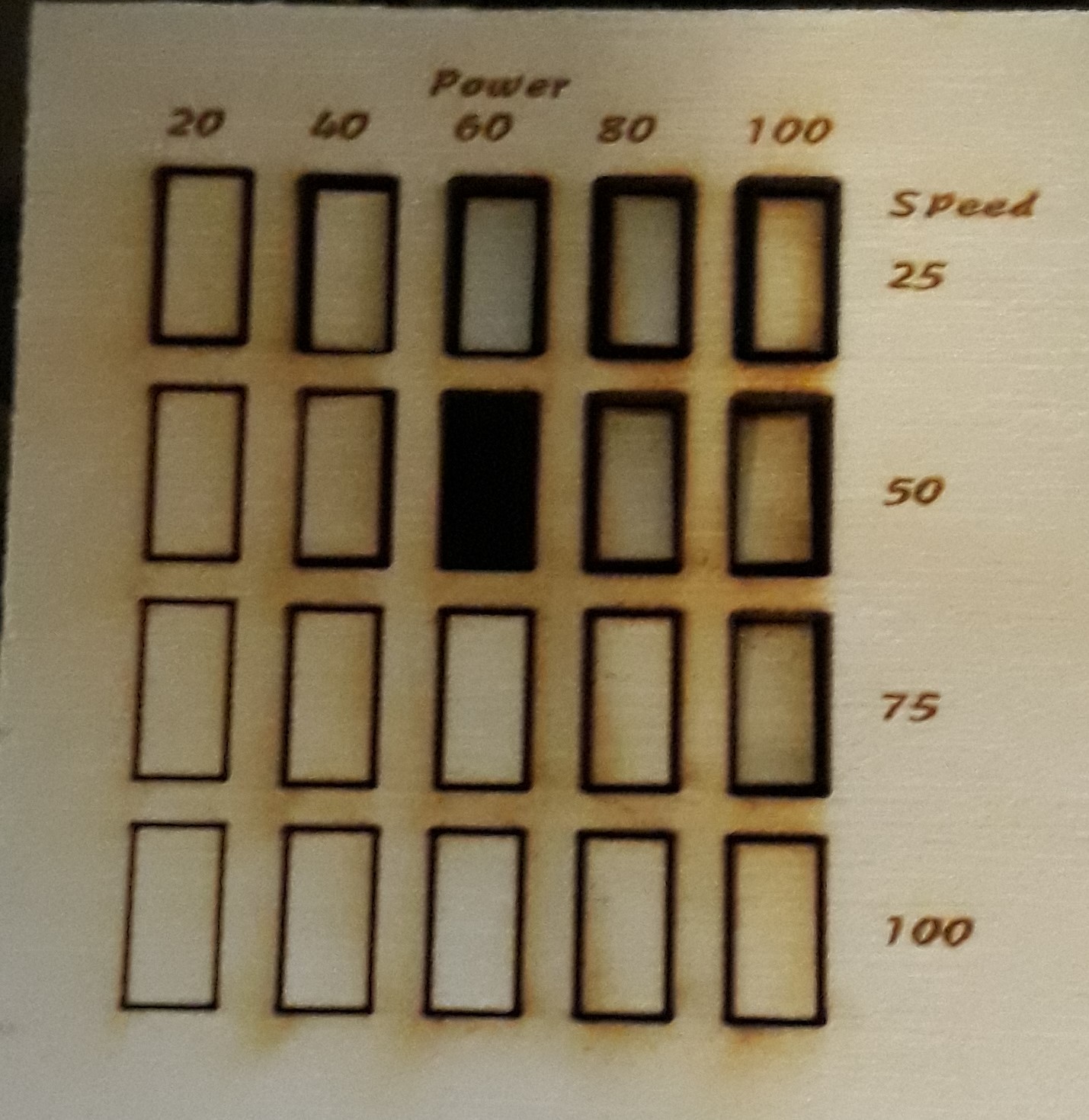
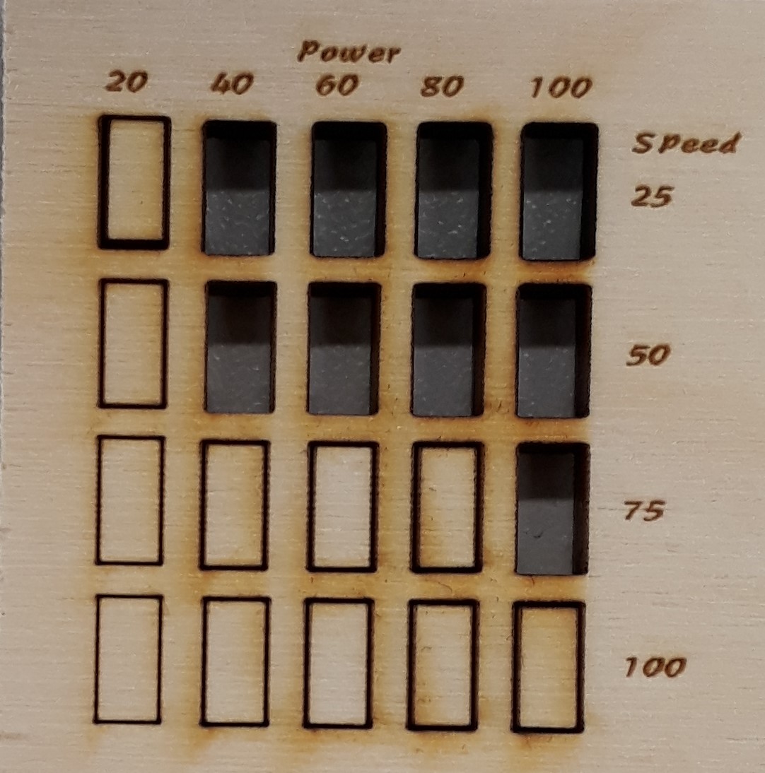
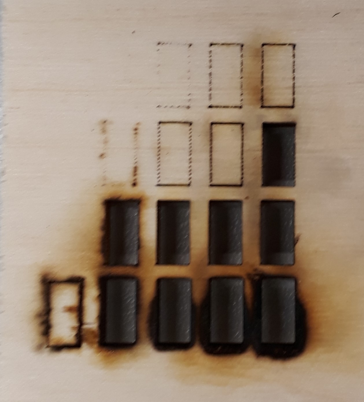
the first picture shows the finished testmatrix in the laserutter. The next picture shows that some settings are not able to cut the 3,4mm thick wooden board. the third picture shows the backside of the cutted matrix. As you see some of the rectangles looks like they weren't cutted but burned out. So more power and less speed isn't always the best solution. Sometimes less is more. At this point I decided, that a setting of Power 60% ans Speed 50% looks like the best cutting result for my 3,4mm thick wooden board. The next step is to find out how thick the cutting-gap is. Therefore I designed the following test-sheet with inkscape and cutted it out with the chosen setting.
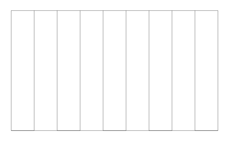
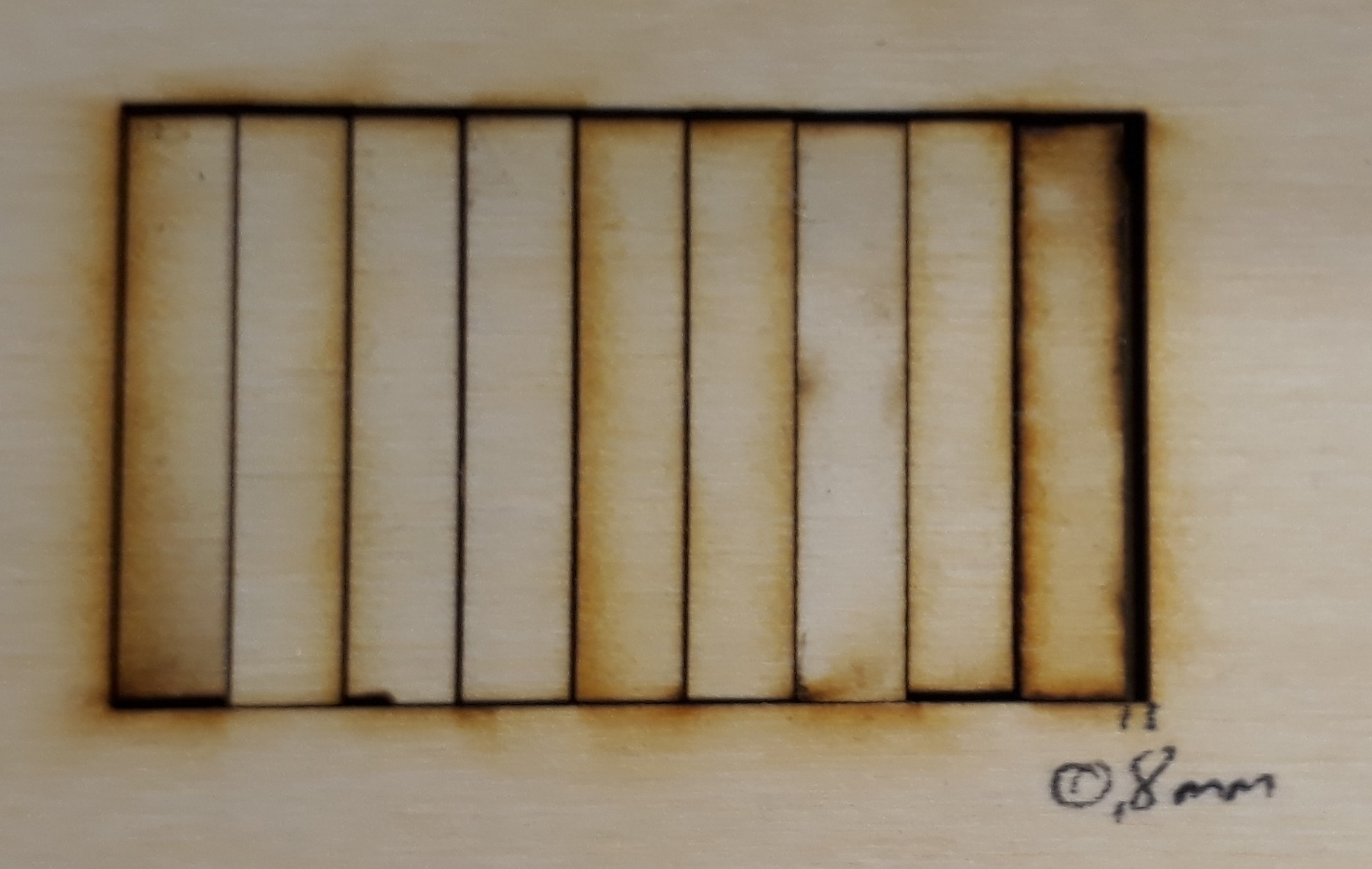
As you see the test-sheet uses ten lines which makes the result more measurable. After the cutting I pushed all single rectangles to one site and measured the gap on the other side. The result is 0,8mm. So each cutting line results in a 0,08mm gap. With this knowledge we can start to design our press-fit system with this material.
My college Aleksandra Konopek used last year nearly the same test to explore the cutting gap. She measured a gap of 2,1mm for 10 cutting lines. The reason of this big discrepancy is the clean mirror. Last year the mirror of the laser cutter wasn't cleaned before the test. So as you see with a clean mirror you can make more precise results.
Downloads
| Cutting Tests(zip) | download |
Tanjas Part:
Characterizing of our laser-cutter part engraving
For Engraving tests I created one table containing different color scales (10 - 100 % black) and different power levels of the CO2 laser (20-80%). First I wanted to see how the engraving image looks like using different settings. After that I would like to engrave one Image with four different technics of engraving (Raster Dither, Diffusions Dither, Muster Dither und Halbton Raster (?)). I created the spreadsheet in Excel and exported it as a pdf. I also exported it as svg, but this led to a bad result in terms of image quality. In the Inscape I imported the table and split the individual columns or removed the grouping. So I was able to remove the superfluous cell formatting and group the numbers in the first column and in the first line for dispatching. Thus, I could send them to the program VisiCut (made by RWTH Aachen), from which the writing was sent to the laser cutter.
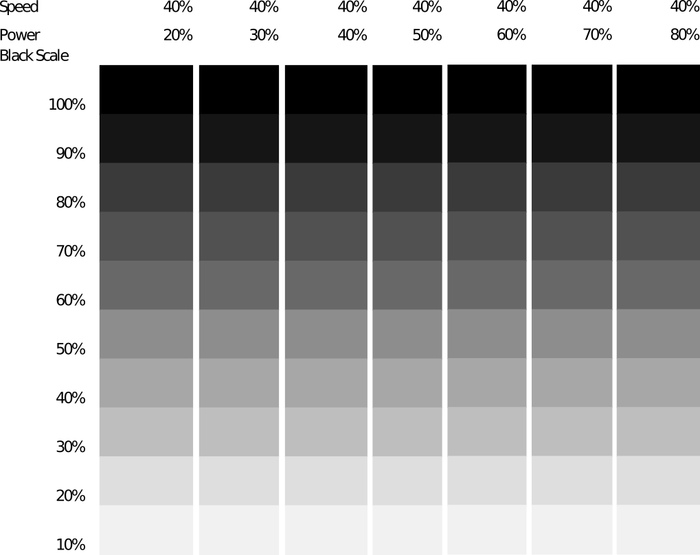
Test image for engraving with different power levels.

Engraved test image for with different power levels using wood.
Unfortunately, as you can see on the last photo of the engraving table, the result has not been even. The reason for this is the slight bending in the wooden slit itself. I did not use cardboard for the engraving since it would have been a fire hazard if I applied 25%. But man can see from the result that in the first column at the power of 20% two last cells with the gray scale of 10 and 20% no engraving takes place. The same is true for the lines of 40% and 50% for the grayscale of 10% of the case. The speed was kept constant at 40% at this table. Therefore, it would make sense to perform such a table for the different speeds and also different foci.
In the following just a short description of the CO2 laser (from www.epiloglaser.com ) which we use in FabLab Bottrop.
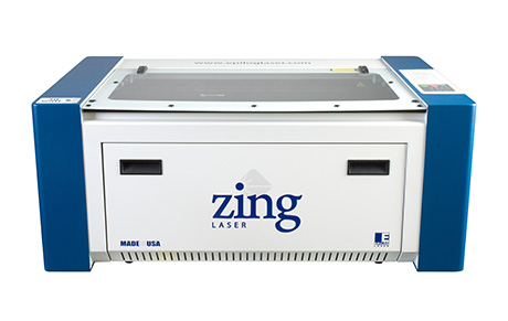
This is Epilog zing 24 by camo and following table contains some specifications of this laser.
| Engraving Area | 610 x 305 mm (24" x 12") |
| Maximum Material Thickness | 197 mm (7.75") |
| Laser Wattage | 30, 40, 50, or 60 watts |
| Air Assist | Attach an air compressor to our included Air Assist to remove heat and combustible gases from the cutting surface by directing a constant stream of compressed air across the cutting surface. |
| Resolution | User controlled from 100 to 1000 dpi. |
Downloads
| Engraving Test Table | download |
Jimenas Part:
For the group assignment I made same tests with acrylic, thick 3mm.
Cutting setting | Test #1
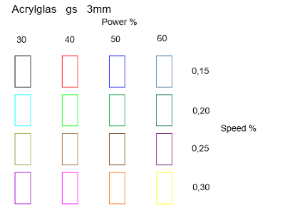
At first, I draw a grid of rectangles (10 x 20 mm) in Corel Draw and set the power and speed values for the laser-cutter. In Corel Draw I loaded the default color pattern from the laser-cutter, so each rectangle had a default color for the settings.
After that I set a new topic for the tests in the material database and entered for each color different power, speed and Hz values ... and the laser-cutter started cutting…
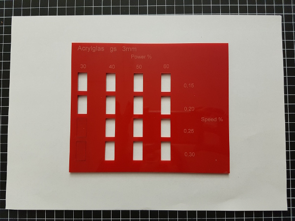
The results were very good, almost each rectangle was completely cut out… so that I couldn’t compare them and made a second test...
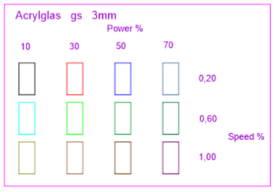
Cutting setting | Test #2
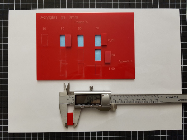
I changed the values for the power and the speed in Corel Draw and JobCenter. This time was the result “better” because I could see which values cut the rectangle out and which didn’t, see the back side photo of the tests.
Best settings: Power 50%, Speed 0,20%, Hz 5000
Kerf: 0,18mm
Download
| Cutting Tests(zip) | Download |
Peters Part:
Laser cutter test
In my test I have examined the frequency setting of the cutter.
In order to regulate the performance of the resonance tube one proceeds similarly as with an inductive system.
Two superimposed modulation types are used.
Once CW this is the actual resonance signal this is usually regulated by feed back to show a stable resonance behavior.
This signal is modulated by a pwm signal.
The base frequency of the pwm can be adjusted in the software.
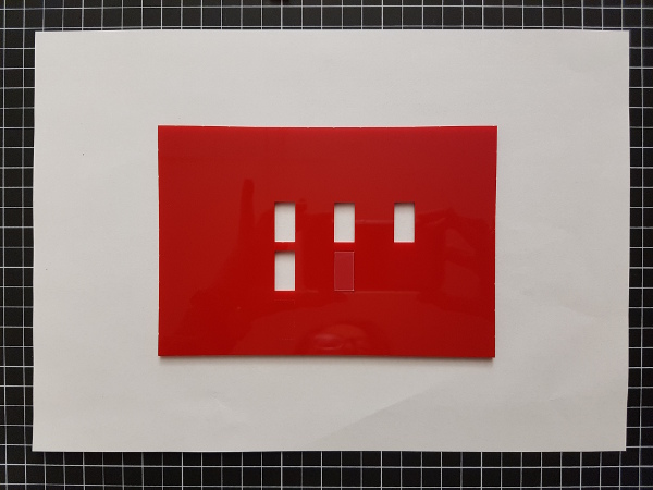
I have tested three different frequencies on a piece of acrylic glass.
(1) 5kHz
(2) 500Hz
(3) 100Hz
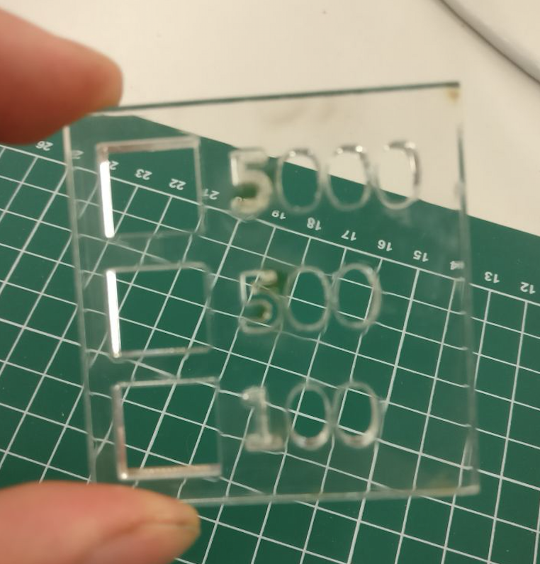
This was the test plate.
With the naked eye you can already see the difference.
The cut edges of the 100Hz cut are sharper and clearer.
Under the Microscope the difference became very clear.
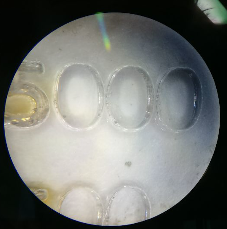
5kHz cut.
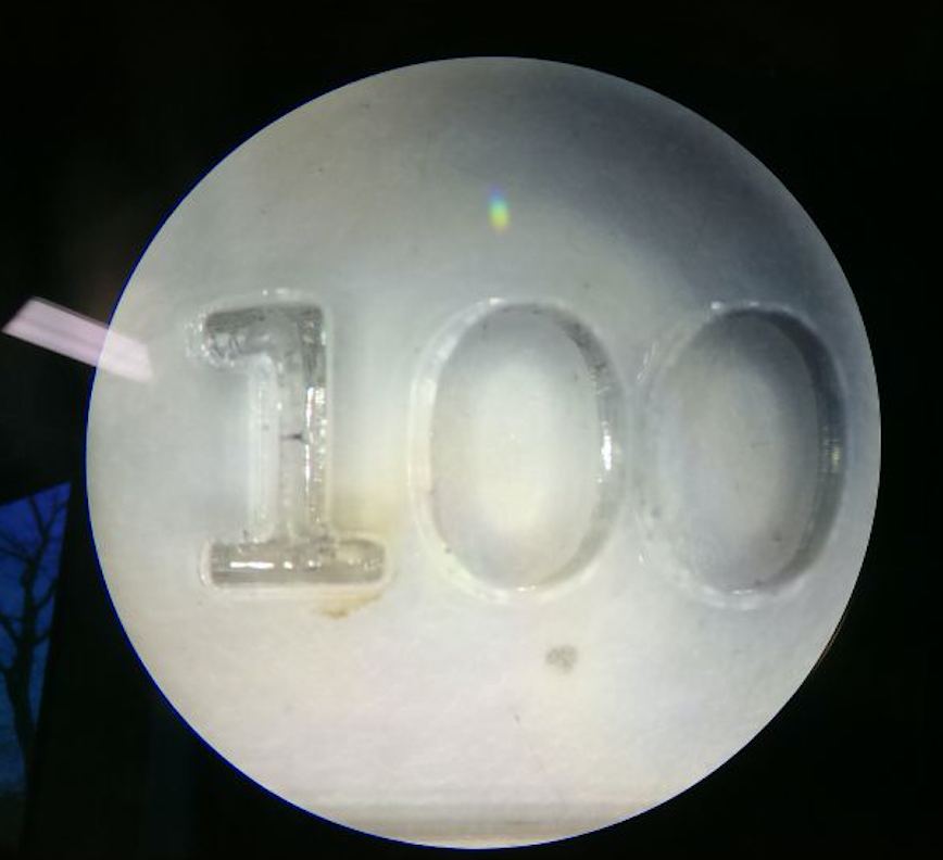
100Hz cut.
As a result I would say that if you want to cut a precise part you should take a low frequency if you want smooth edges and you should take a high frequnz.
Why is that ?
When the duty cycle of the PWM is high, energy is constantly being brought into the material.
This is how the edges run in heat-sensitive materials.
When the duty cycle of the PWM is low, the spike discharge is high.
This way, the laser beats the material in a short burst of energy and thus brings little energy into the material.
Daniels and Christophs Part:
Kerf Test
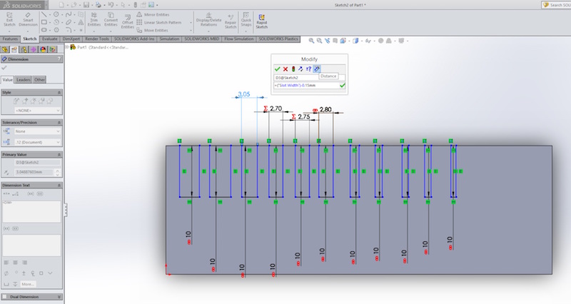
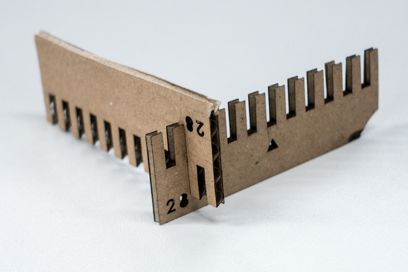
To test the Kerf of our Zing 6030, we had to design a parametric testing comb.
The slot in the middle, above the triangle is 2.8mm wide, which is the thickness of the cardboard we used. The slots on the left and right side, scale up and down in 0.05mm steps, so we were able to test a press-fit construction in a range between 2.55mm up to 3.05mm.
We linked the different slots to each other, which allows you to change the slot dimension to verify other materials but hold the 0.05mm spacing.
Linking dimensions in SolidWorks is very easy. Go into your sketch, make a right click on the dimension you want to link, then enter a name for this value and click on ok. There is even the ability to make a equation with these linked dimensions/values to make driven dimensions. This is helpful to make a (nearly) complete parametric model.
The perfect press-fit joint was reached at 2.6mmm, as both parts hold together secure, but won't press or destroy each other.
Download
| Kerf Test as SolidWorks part | Download |