final project overview:
the time for this project requires alot of resources and time.
my final project is to build a cup product which simulates the liquid level as cool animation for Juice Bars
- the cup should should simulate the liquid following gravity when is tilted ..
this is a project that i intend to sell to some
juice barsas decoration tool that people come and enjoy the experience of it and can take video snaps of it..
Large scale idea:
the original idea is to build a platform that connects shops with their customers
a service provider gets a Point of Sale system with customer database:
- each regular customer can take RFID card or medal which has unique id.
- everytime the customer buys a product, he can scan his RFID card in a device that is connected to a computer
- he can see some display in the cup showing status, virtual points he earned, and some
cool animationsthat are related to the service provider - the computer process the information of what each customer buys, virtual points, and statistics.
- the service provider can set products with two prices, “real money” and “virtual points”
a customer can benifit from his virtual points and get special offers from different service providers ..
- this product can be connected to different shops with different products and create virtual points that you can buy from different service providers that are subscribed in this product.
- each service provider catagory have different device shape,
cool animation, and pos system..
DESIGN CONCEPT
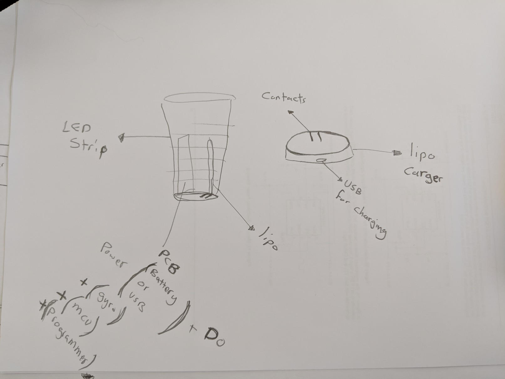 as you can see, the cup should indicate the liquid and simulate it when the cup is tilted ..
im planning to use the following:
as you can see, the cup should indicate the liquid and simulate it when the cup is tilted ..
im planning to use the following:
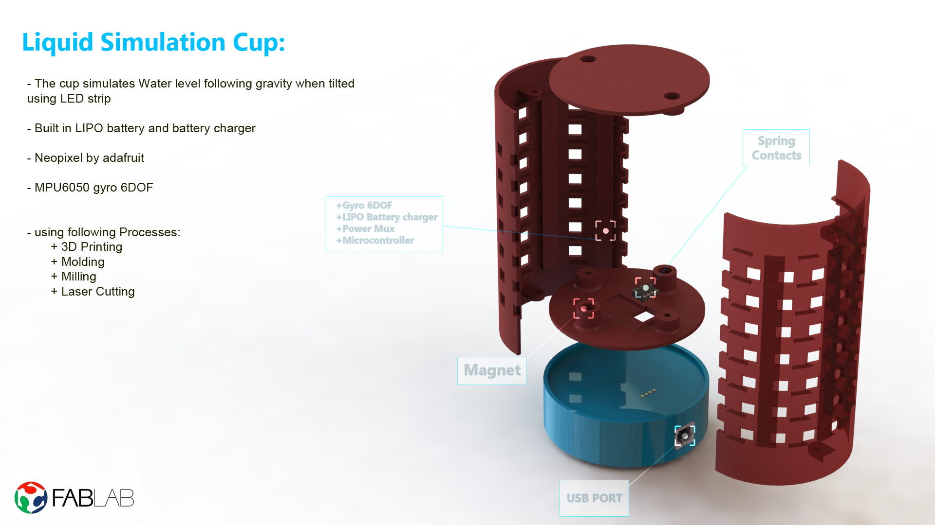
- Addressable LED strip and diffuser for the indication
- Gyroscope to get the tilt angel
- microcontroller to measure the angle and output to led strip
- Light battery to run the cup without wires
- Dock station to charge and update the firmware
so i want to detect the tilt angle of the cup and simulate liquid level on the cup through addressable led strips.
my initial idea was to include RF ID where customers can scan a loyalty card and visually see the amount of credit accumulated. But after starting the project I was not able to implement that functionality. It is a part of my future plan for development
Component Selection
im planning to use the following components:
- 3d print, mold for some structure
- cup structure that fit components inside
- paint
glossy black - addressable RGB led strip
ws2812b - 6 axis DOF:
MPU-6050 - microcontroller
atmega328 - microcontroller
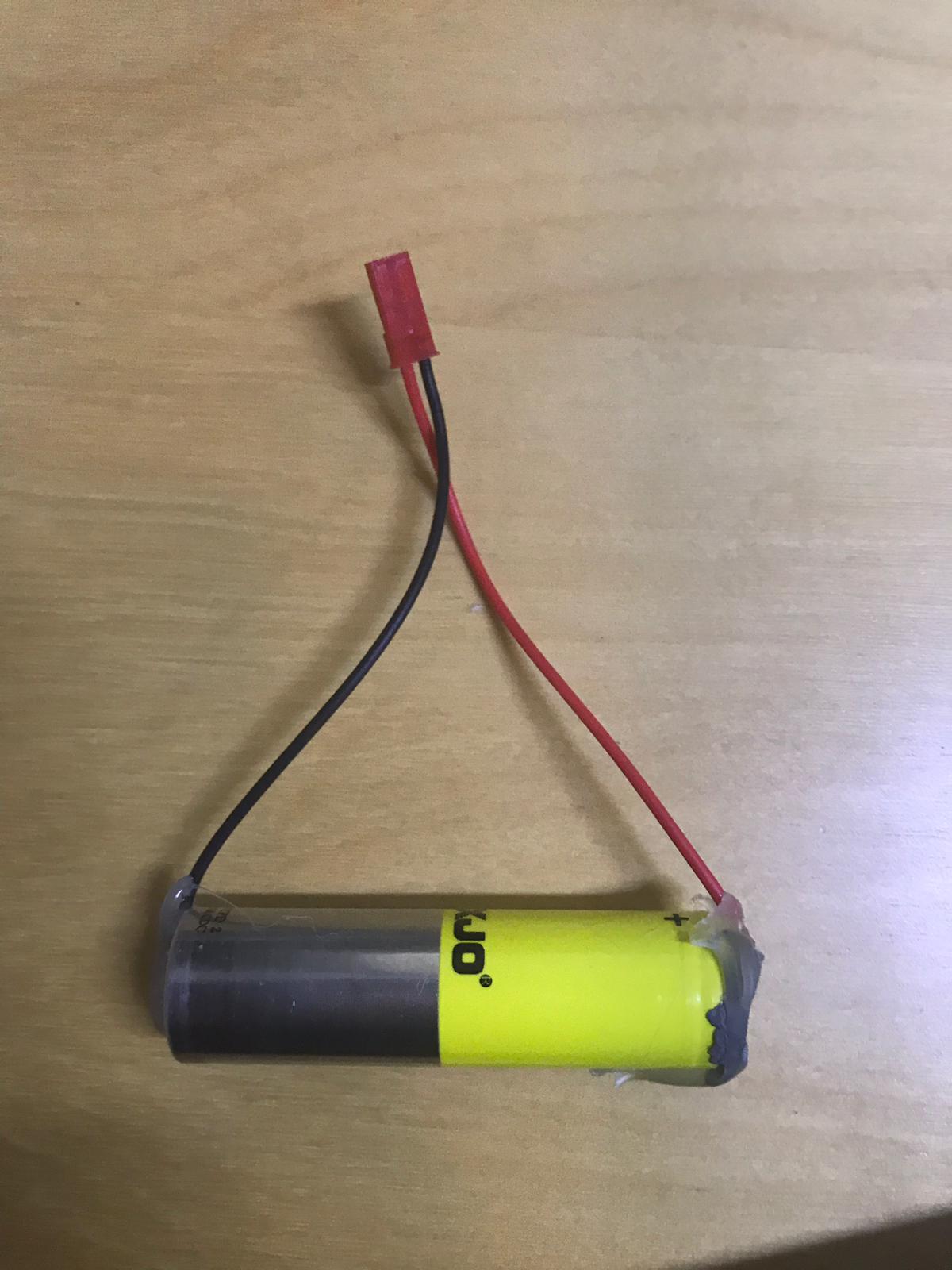
atmega16u2for programming with USB - lipo battery in cup
should have high C-rating to discharge - lipo charger
- duck station
3d printedprefer snap-fit design - USB connector
USB MICRO B - contacts from cup to duckstation
Digikey: 1212-1448-ND - magnet to snap-fit
Design
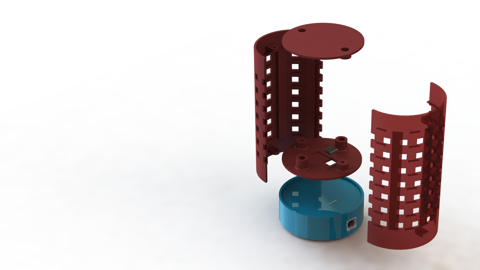
i used solidworks to design my cup with all the components. The cup consists of multiple different parts. There is a charging dock snap fit bottom that is meant for charging with magnets to guide the cup for snap fit. The cup itself is made from three parts, the bottom of the cup with magnets attached for snapfit, the side with the leds attached and a cover layer to cover the leds for a nice finished look.
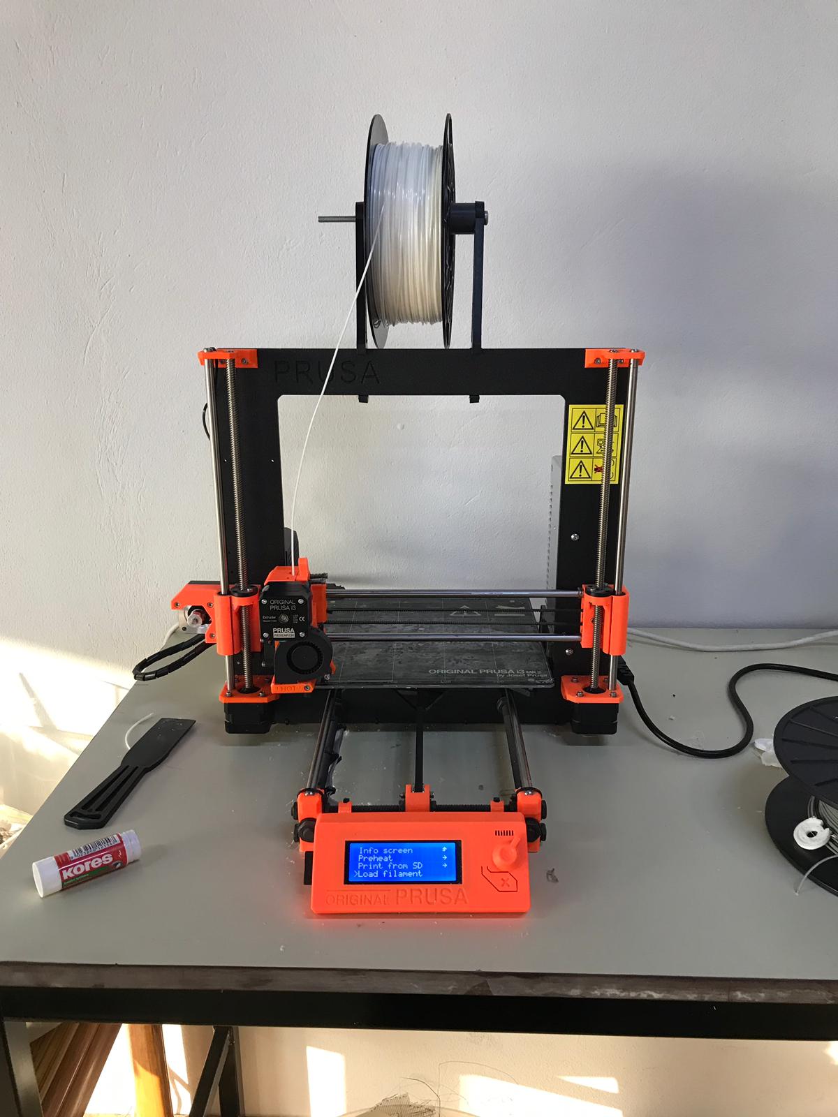
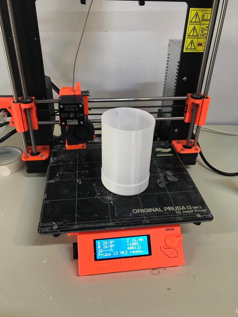
i print most of the design using PLA filament on a prusa 3d print machine.
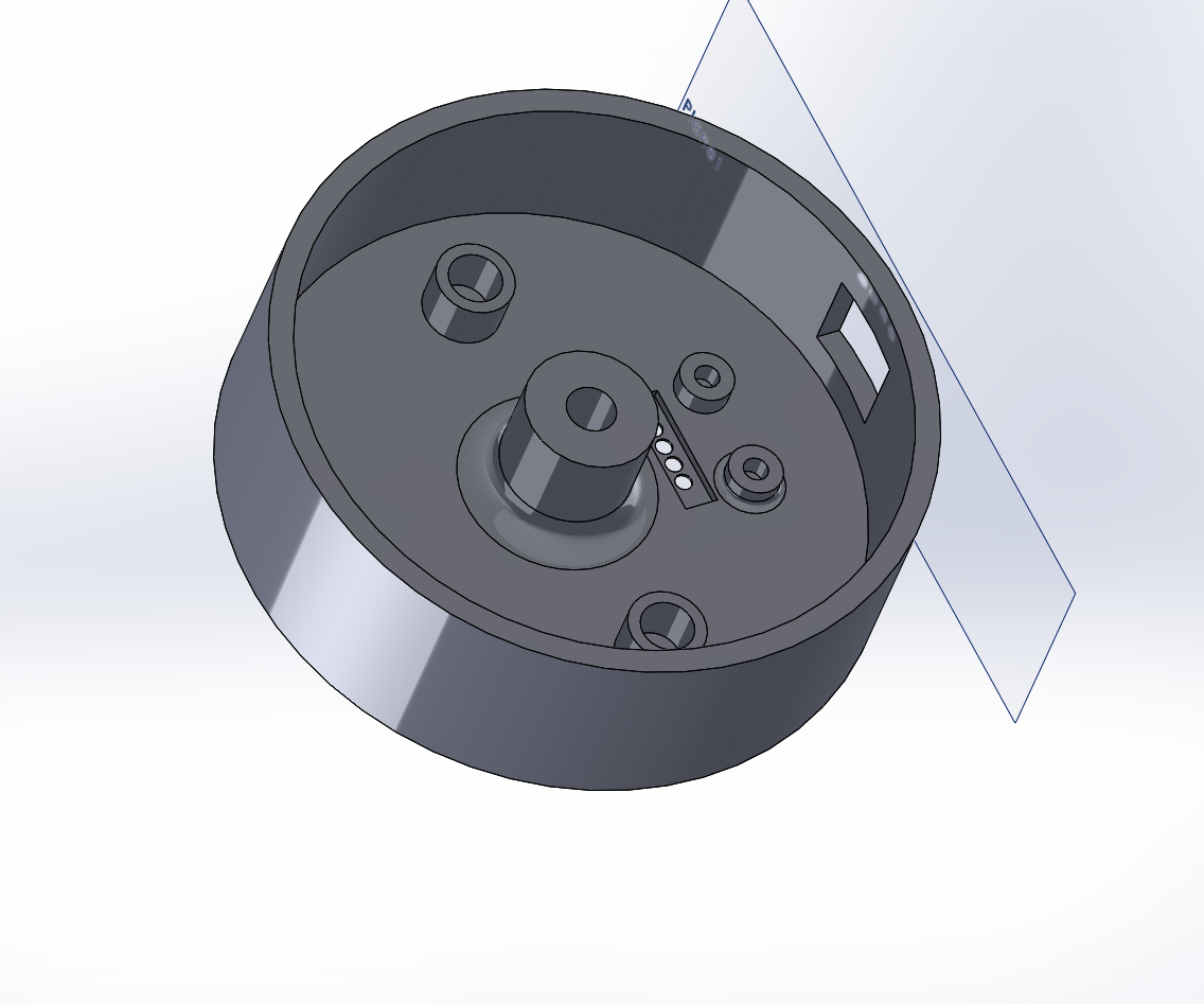
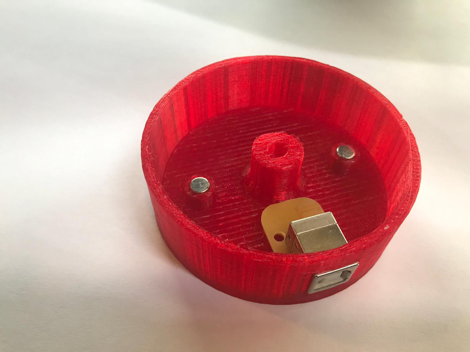
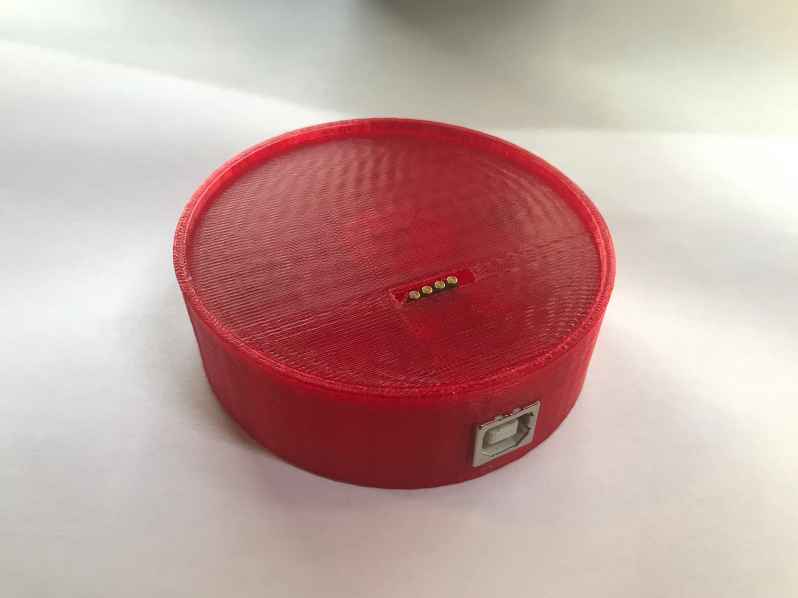
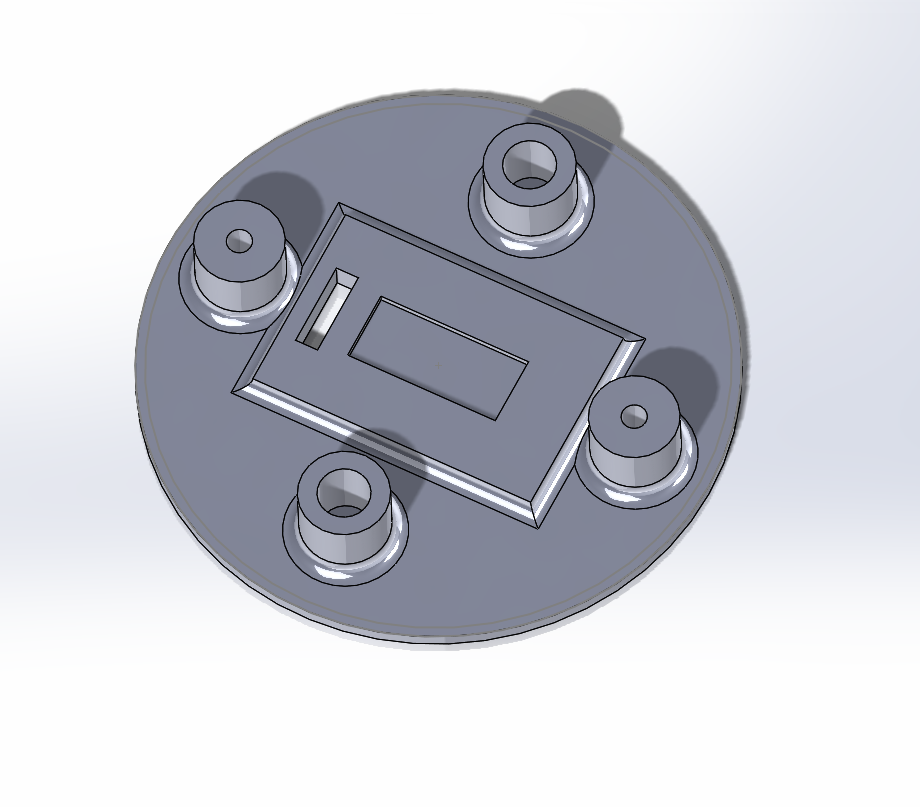
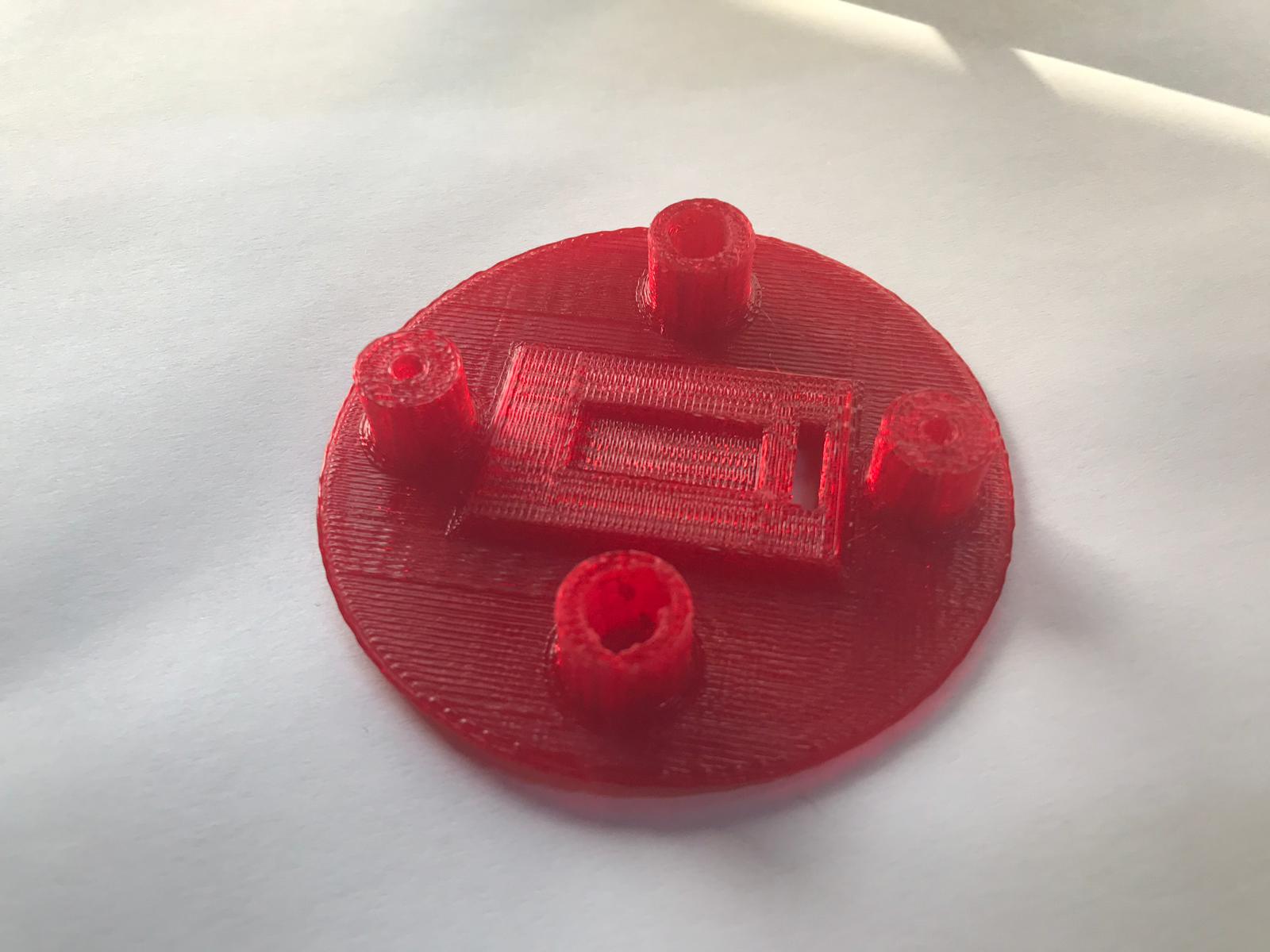
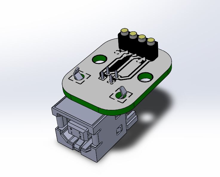
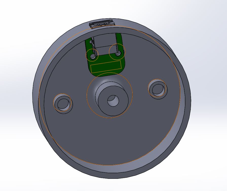
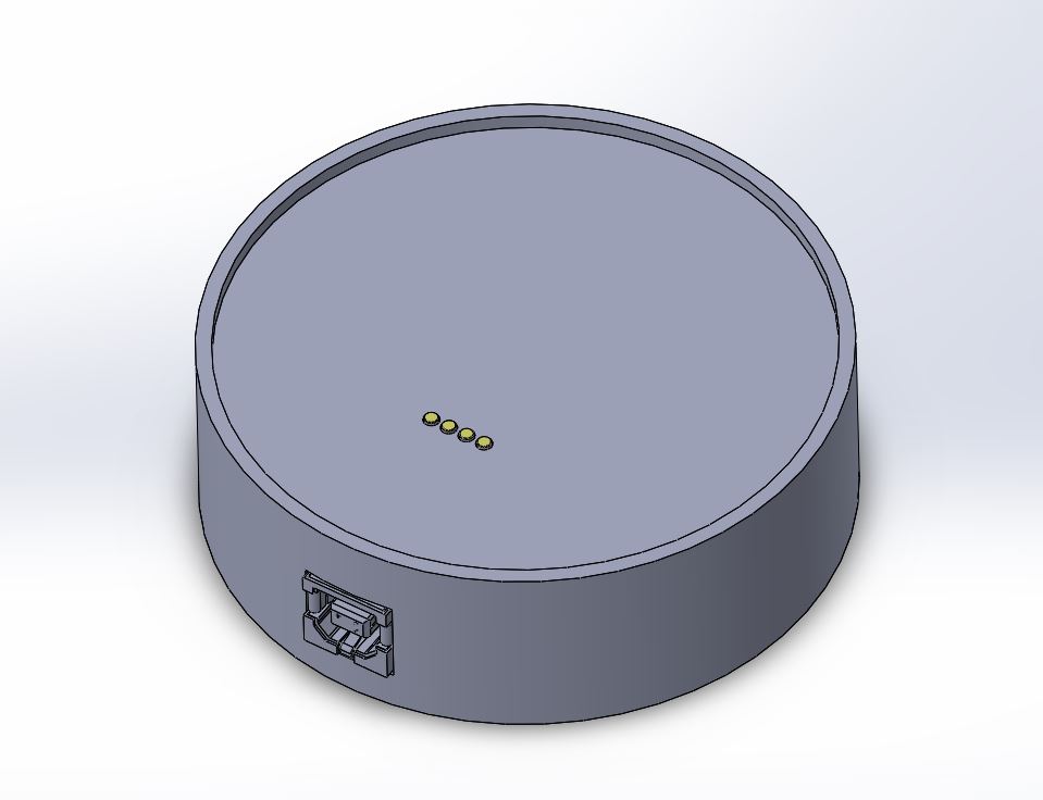
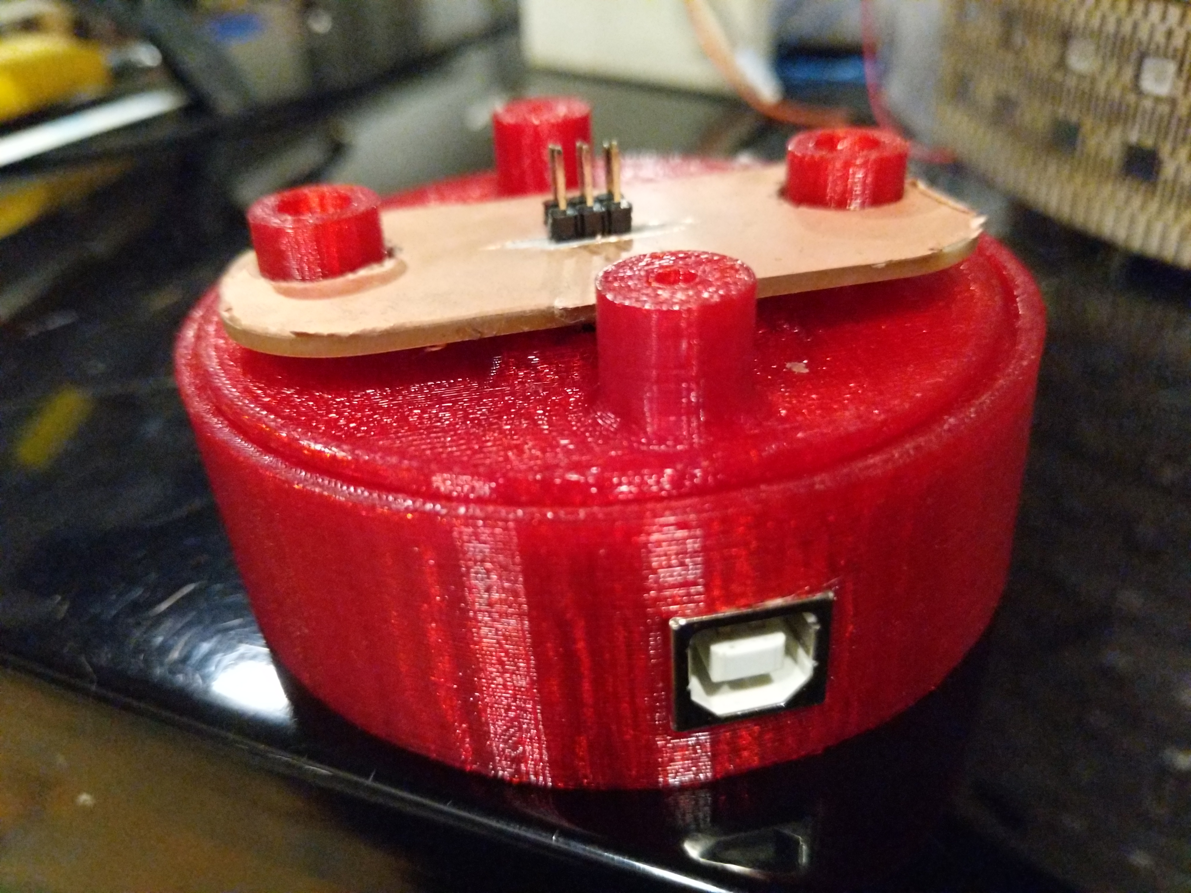
base
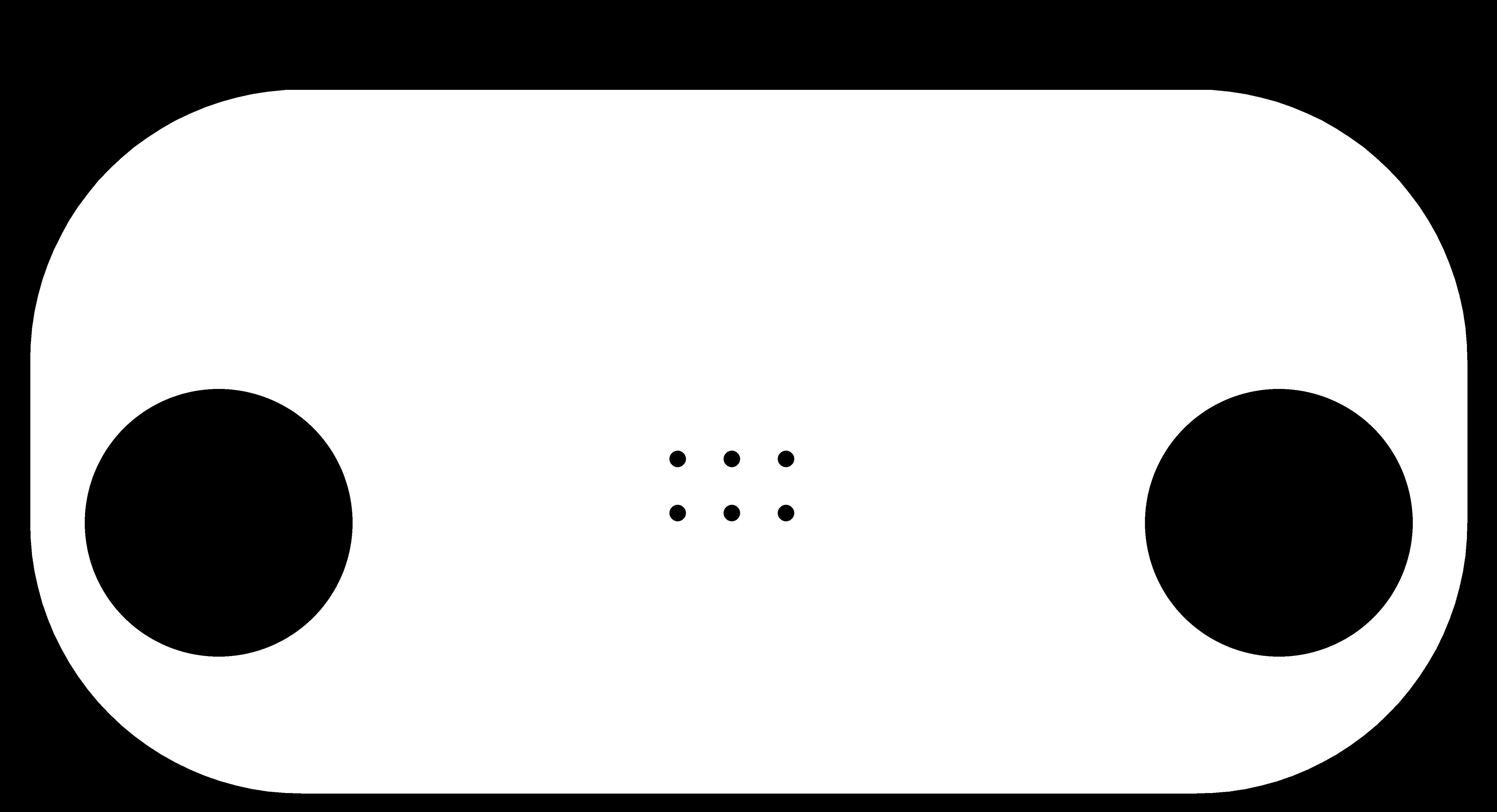
ive made the base for snap fit charging and firmware update of the main circuit. i made the base in solidworks with space to fit a circuit at the bottom, a hold for the usb connector and two slots for magnets for magnetic fit with the top cup. The hardest part for the base was to make the charging hole (the connector that connects with the top part of the circuit) alligned right with the top cup and with the circuit which was made in eagle.
download stl
download solidworks
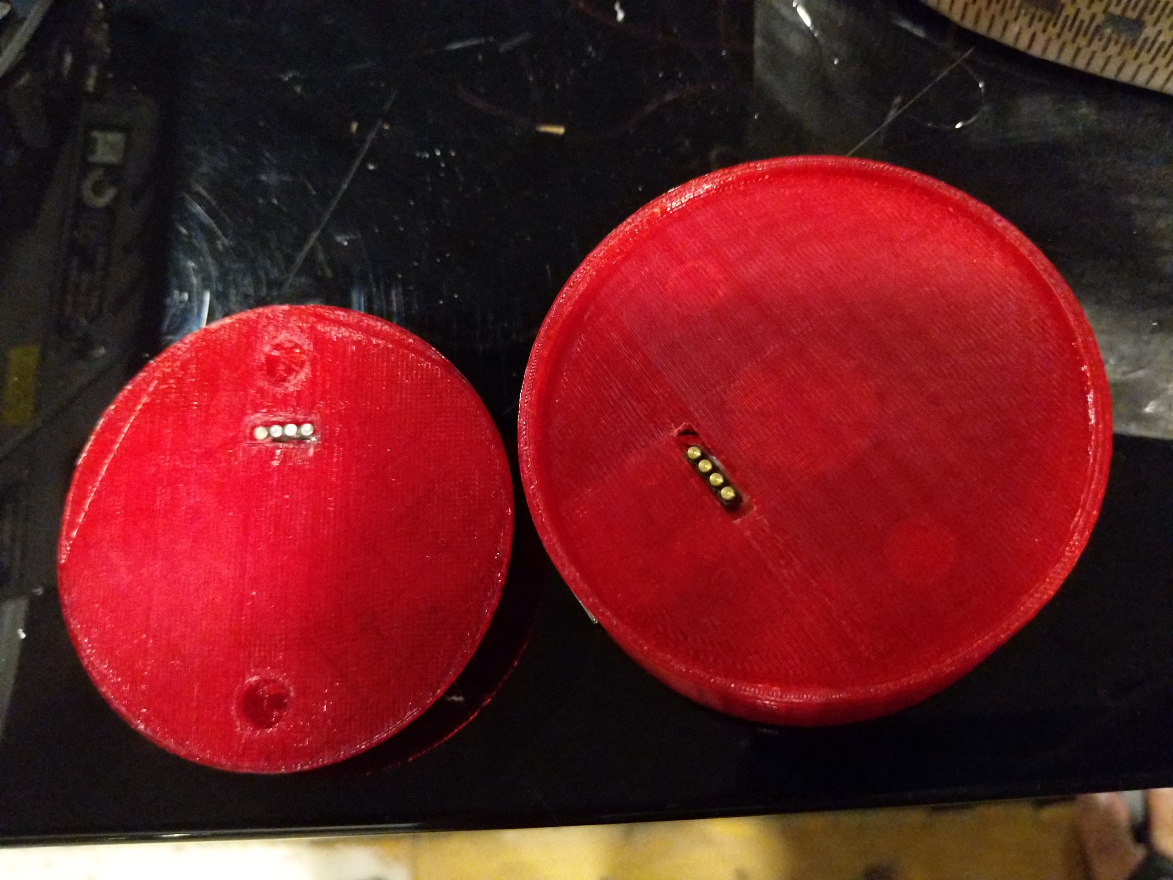
cup bottom
for the cup bottom it has to fit with the base for correct charging. the cup bottom has two magnets for snap fit align with base and with hole for the circuit connector. i designed it in solidworks. the design is made to fit a circuit on it and be the bottom of the cup which is detachable.
Failed design
the first design i made for cup bottom was way too bulky and the screw place was not thick enough to handle the screws. when i tried to screw it in place it broke. it also didnt have a place for magnetis i was just gonna hot glue it on but thats not a very good design idea
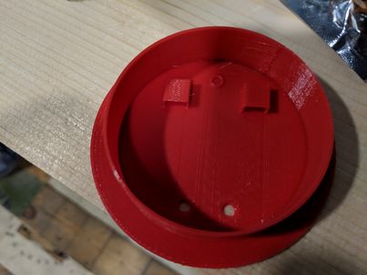
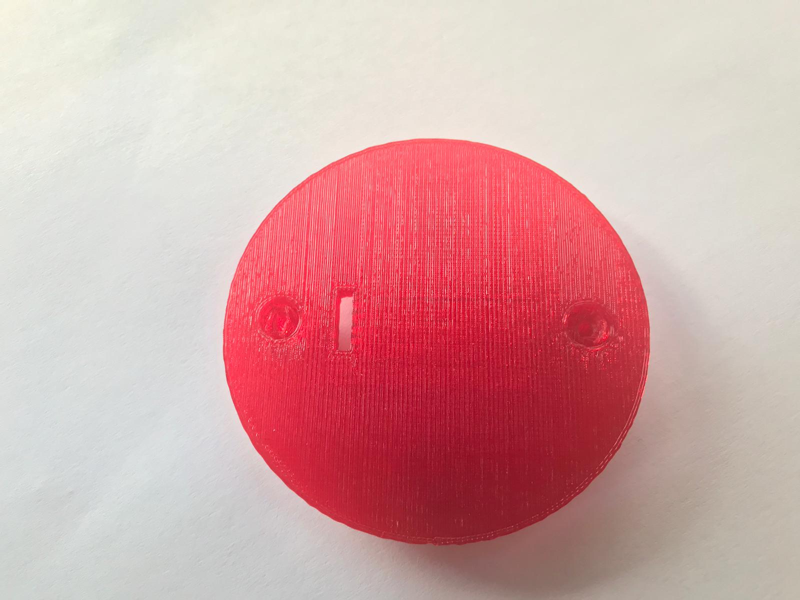
successful design
the new design is slimer from outside but the screw place is stronger and can handle the screw. there is also a place for the magnet to hold in place with a place for the charge connector.
download stl
download solidworks
cup body
this was the hardest part to make in the cup. my idea was to make a body with slots to fit RGB led strips in excactly so the only part facing out is the led part. i tried multiple times with different designs
design 1
first design i tried was to make it in 2d and laser cut it on thin plastic sheets. i made the design with inkscape
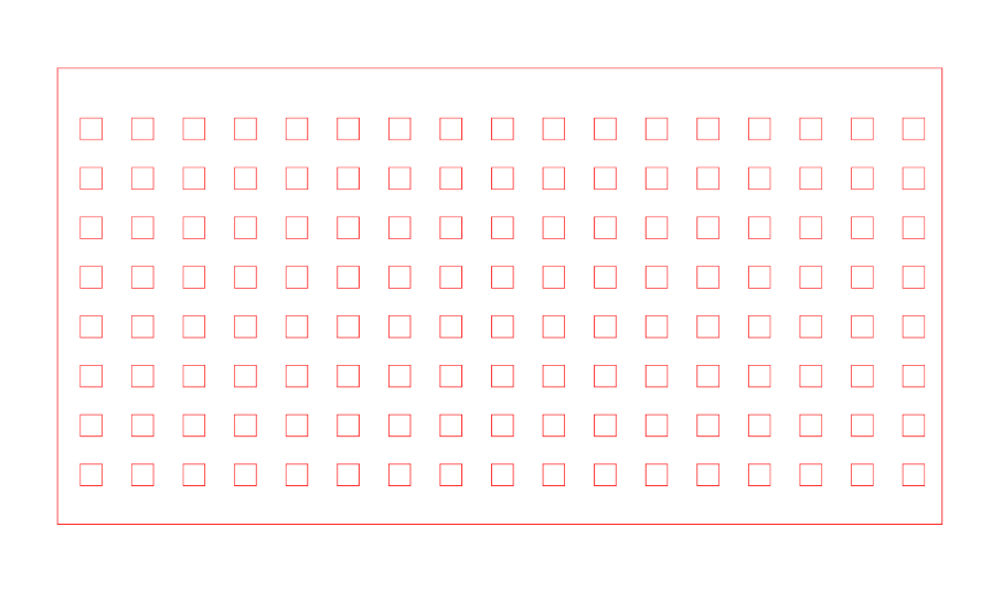
i didnt cut this design. the plastic sheet was not goiung to be flexible enough to bend around so i had to come up with different design
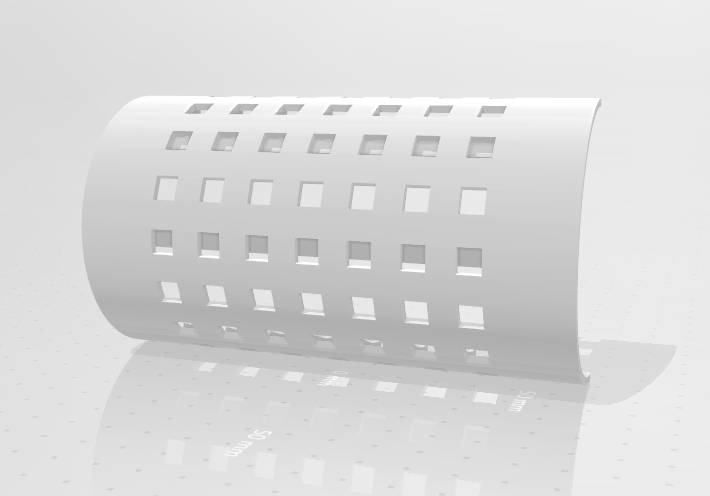
design 2
this design is similar to the one before but the difference is it has extra slots to add flexibility to the design to be able to bend it around in a circle to form the cup. this is good trick to laser cut hard materials like acrylic and make them flexible and bendable.
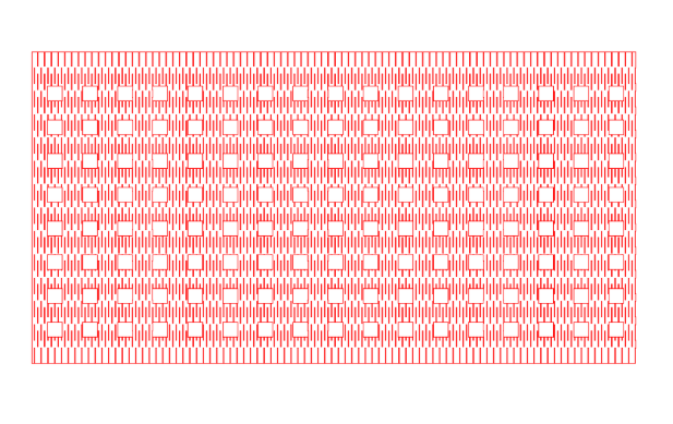
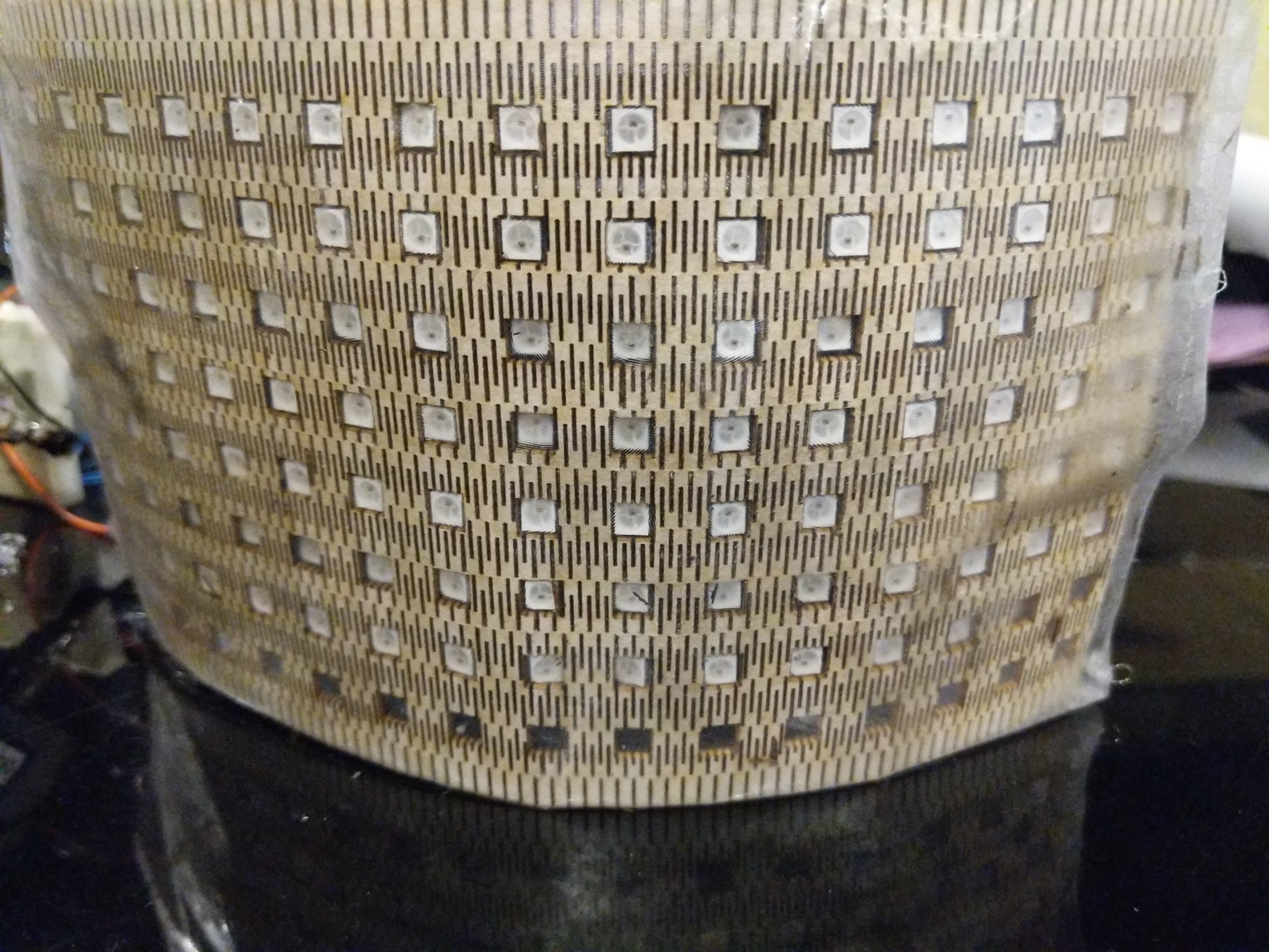
as you see from the picture the problem with this design is that it is not alligned right with the leds on the led strip so it was off center for some of them on the sides. ythe point of this part is to fit perfectly on the strip so thats not gonna work. plus it turned out too flexible and not very strong which is not ideal for the final look of the product
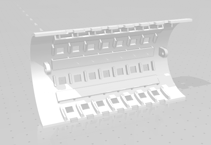
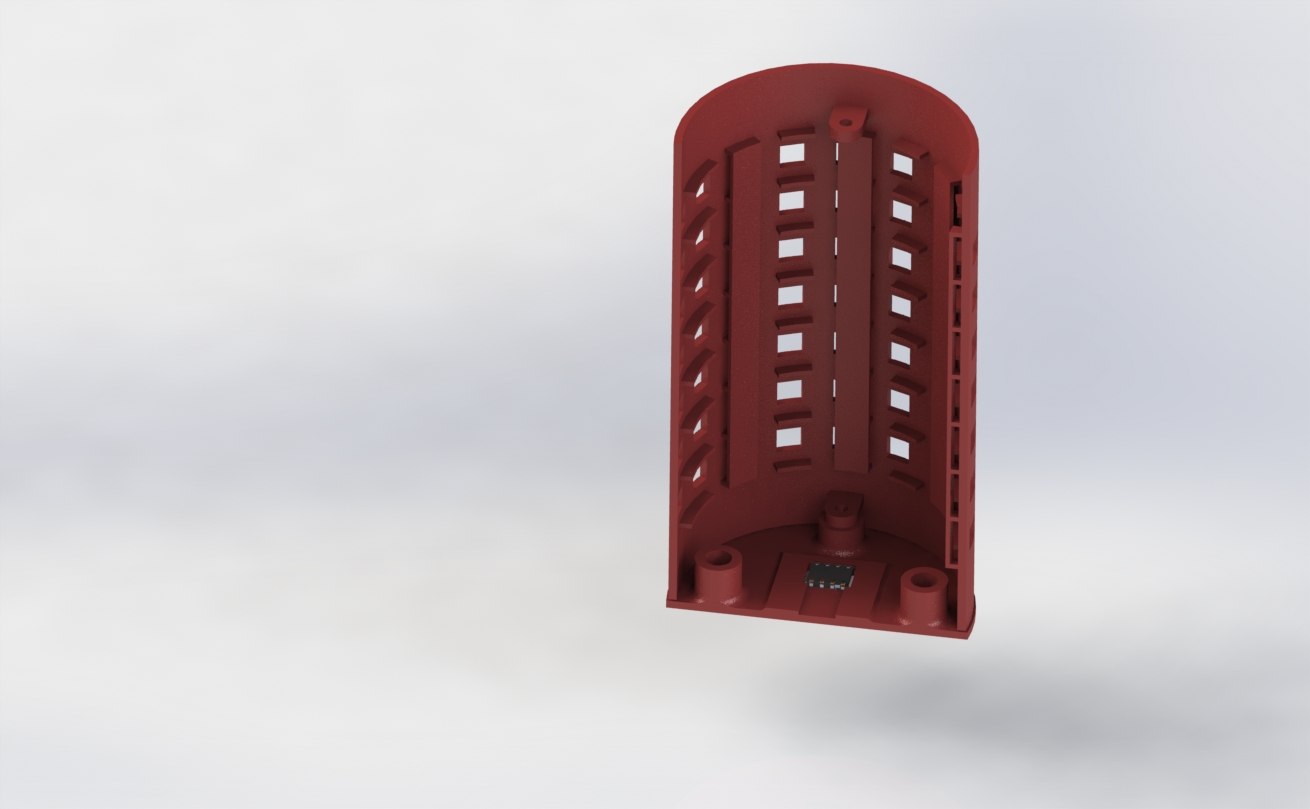
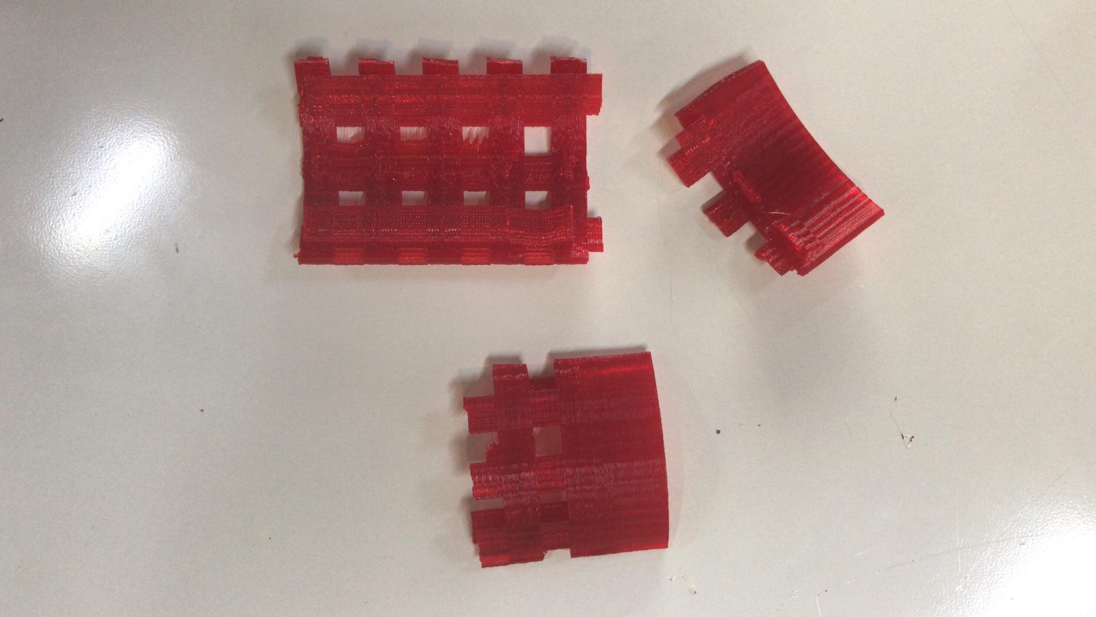
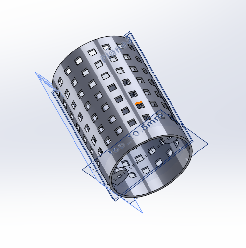
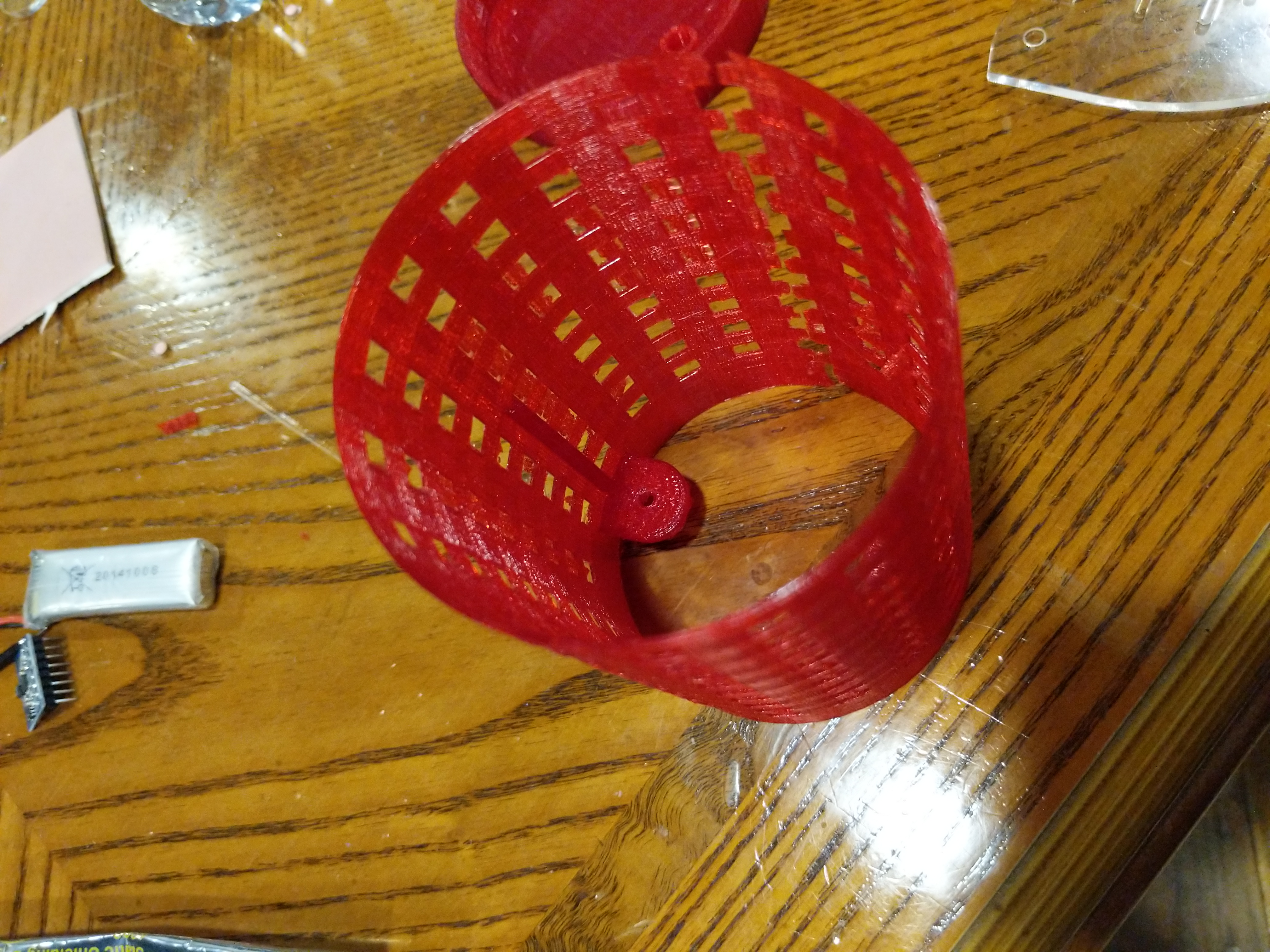
design 3
next design was made as 3d design for solidworks. the design idea is to have housing for the leds to fit and to 3d print the whole cup body out of PLA.
i started with 3d printing only half the cup to check dimensions before 3d printing the whole cup and wasting time and filament. it kind of worked but was hard to slide the led strip in becuase the hole was too small. i put one led strip in to test it and and when try to pull it out again to adjust and solder connectors it wouldnt come out it got stuck and i had to break the part to get it out. and the hole alliginment was not exactly correct here too.
 download stl
download solidworks
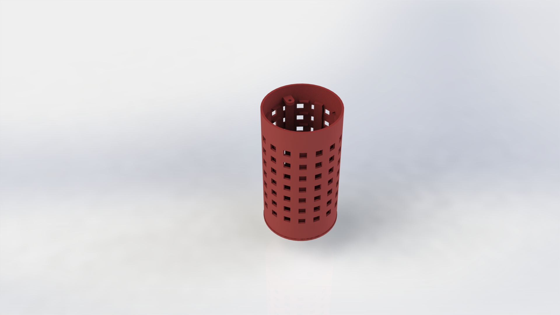
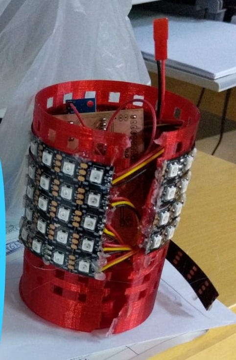
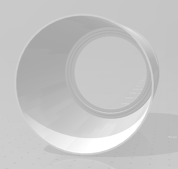
design 4 - final
fourth design was for 3d printing and designed using solidworks. printed using red PLA filament. it is a very simple design and less complex than the one before. it is simple cup body with holes to hold the led strip in place that is printed very thin.
download stl
download solidworks
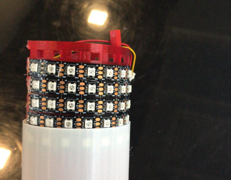
i put the led strips all over it and it worked pretty well as the cup body
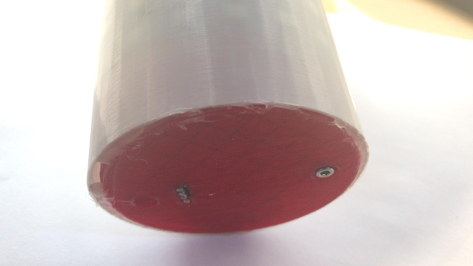
cup cover
to cover the led strips and make the cup have a nice finished look i made a cover with white PLA filament that fits right on top of the other components. it is in white so the led light color would show through the cover. it will be a little dim because it is covered but it will show.
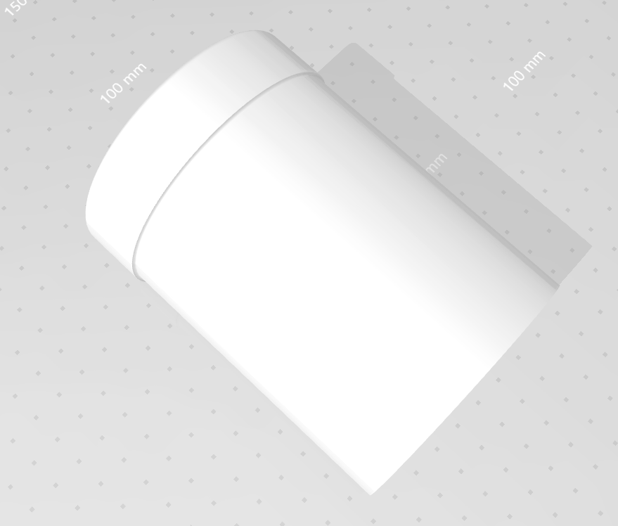
it print okay and it fit over the LEDs. it is a tight fit tho. i would ideally make it a little bit larger but it works.
Electronics
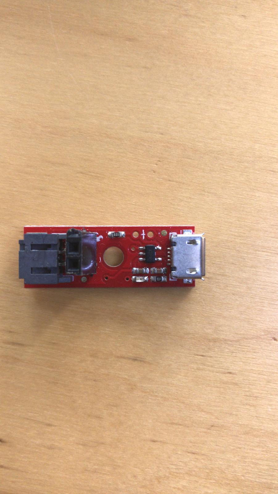
charge circuit
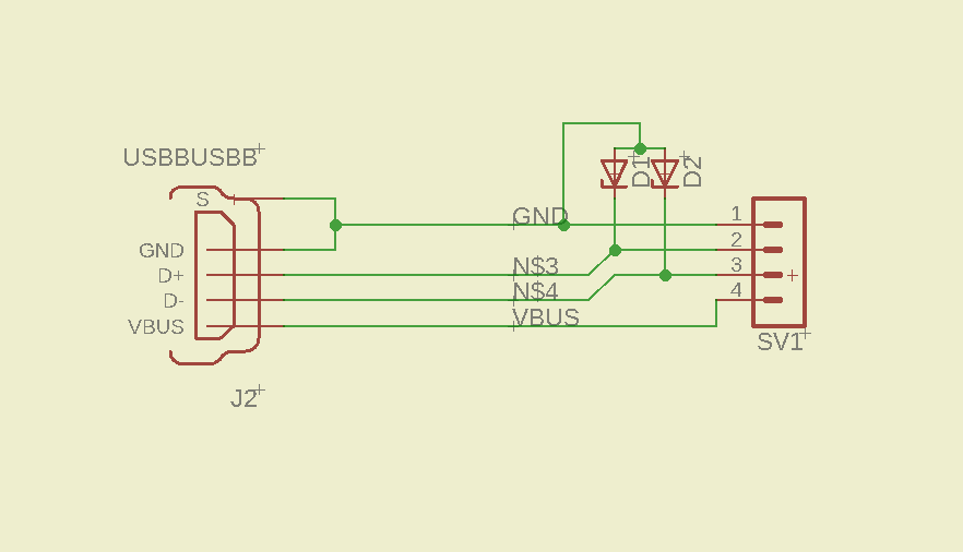
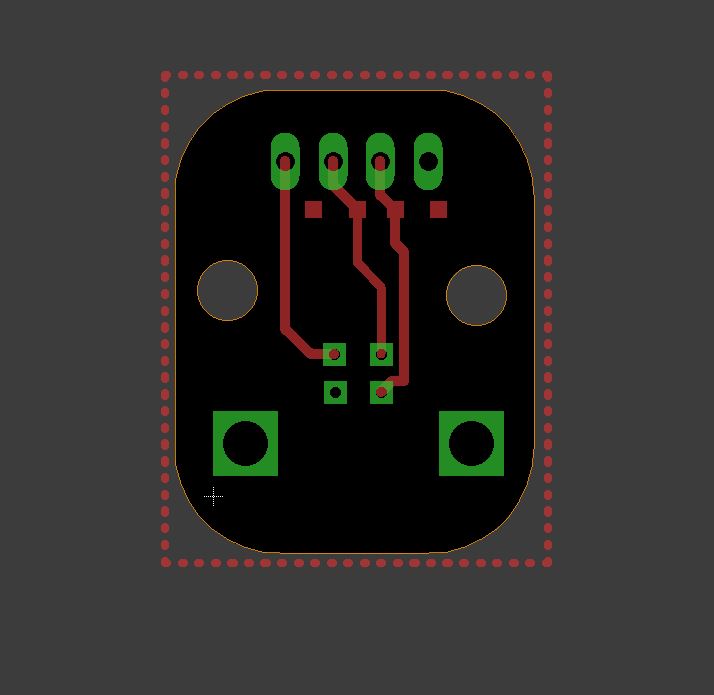
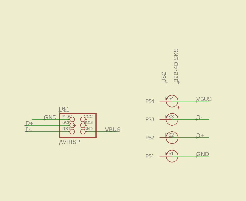
This circuit only works as gateway for the charging. It works as link between the usb cable and the battery charging module
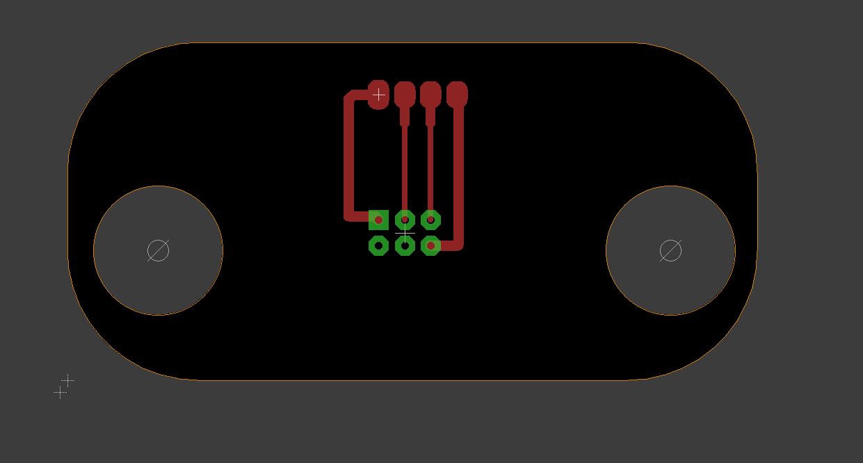
I made the circuit using eagle. It contains only two components but the sizing and layout of the board is very important. The board has to fit in the cup base and has a connector on top that connects between it and the top circuit in the cup. It has hole for the screws to hold it in place. The UsB header type is USB B
charge recieve circuit
this circuit is used to line up with the circuit at the bottom and recieve the power from usb cable connected. it works by aligning with the bottom circuit header and gets power and data for programming. the cup base has slots for the circuit to fit right in it to be perfectly aligned.

battery charger
To charge the battery i am using battery charger module purchased through digikey. it is a SparkFun LiPo Charger Basic - Micro-USB to charge a 3.7 single cell li-ion battery. i am connecting this to the power circuit so i charge when a usb cable is connected. to detect when power is there i connected power in of this circuit to IO pin of microcontroller circuit.
I am not using usb micro header here. i connected header to it.
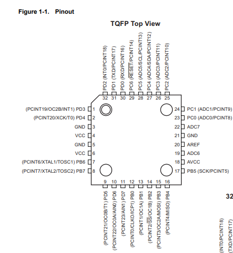
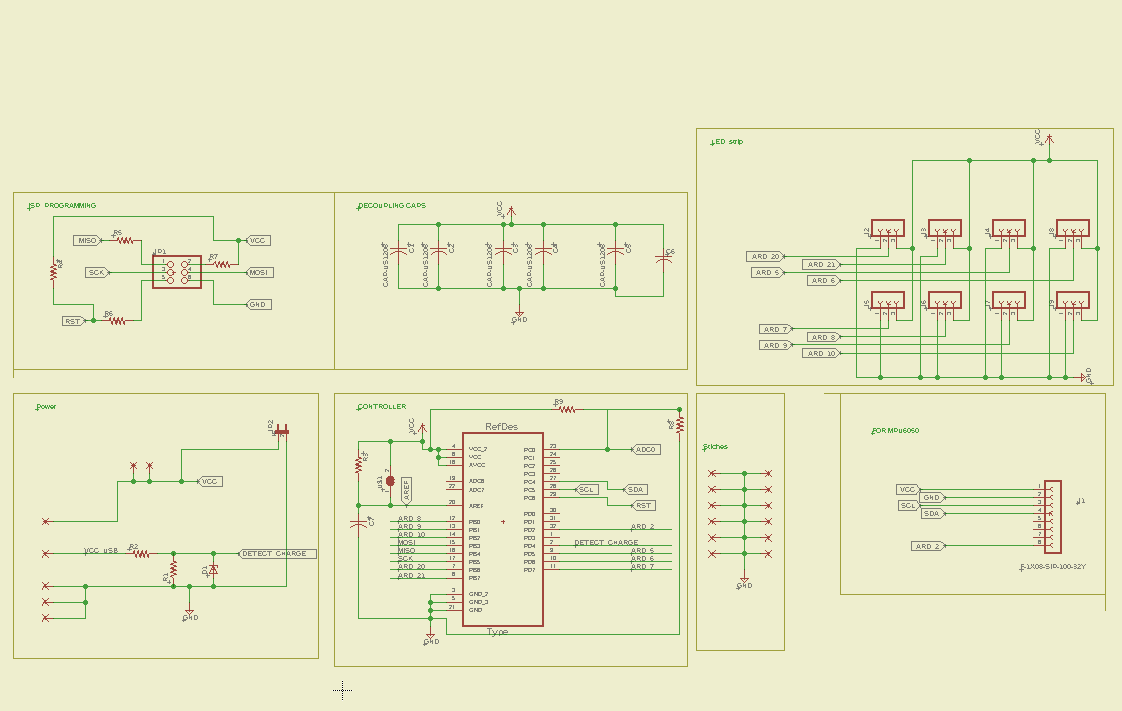
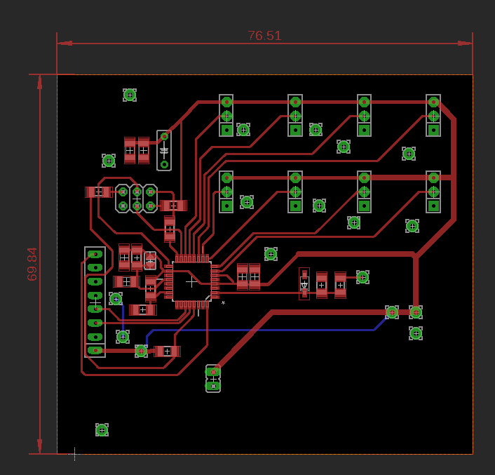
main microcontroller circuit
The microcontroller circuit is the main important part of the cup. it controlls the operation of the RGB LEDs and reecieves and processes the data of the gyro so the cup actually works. i am basing the microcontroller circuit on atmega328p microcontroller becuase it is one of the most popular AVR microcontroller and there are so many resources to be use it online. it is also a lot more powerful than the attiny and can handle driving thew rgbs and processing gryo location data.
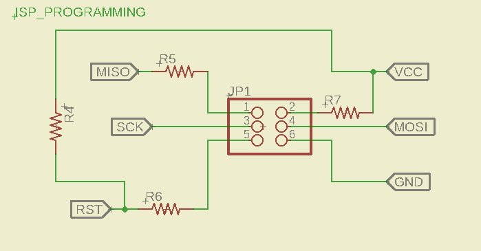
first part of the circuit is programming. i am progamming the circuit with my isptiny programmer so i need isp header for the programming
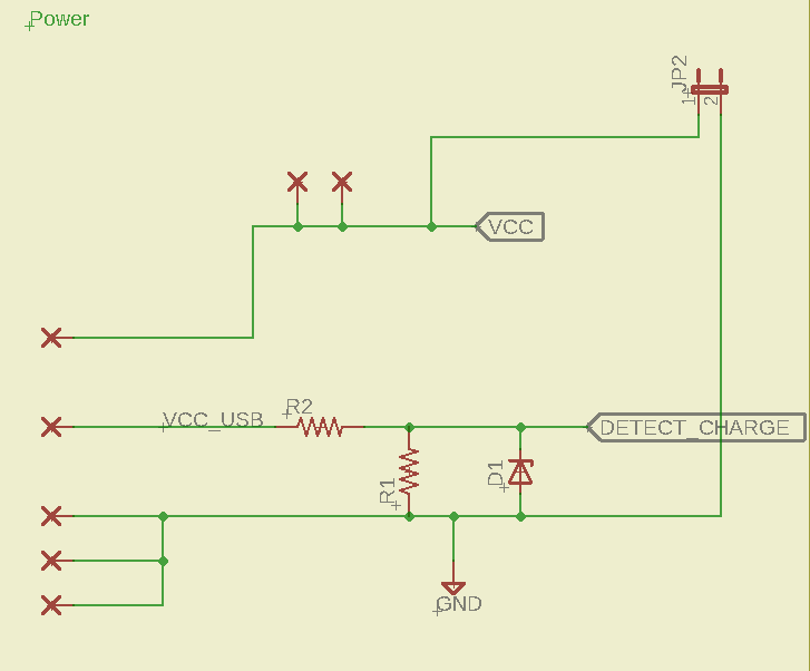
second part is the power. i am getting power from a lithium ion battery and i have a power detect pin that gives powert signal only when usb cable is connected
most importang part of the circuit is the microcontroller. microcontroller used is atmega328p.
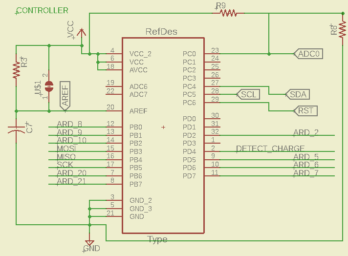
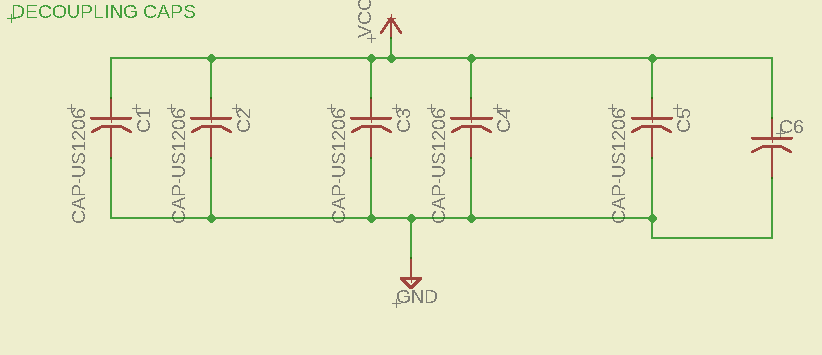
i am also using decoupling caps
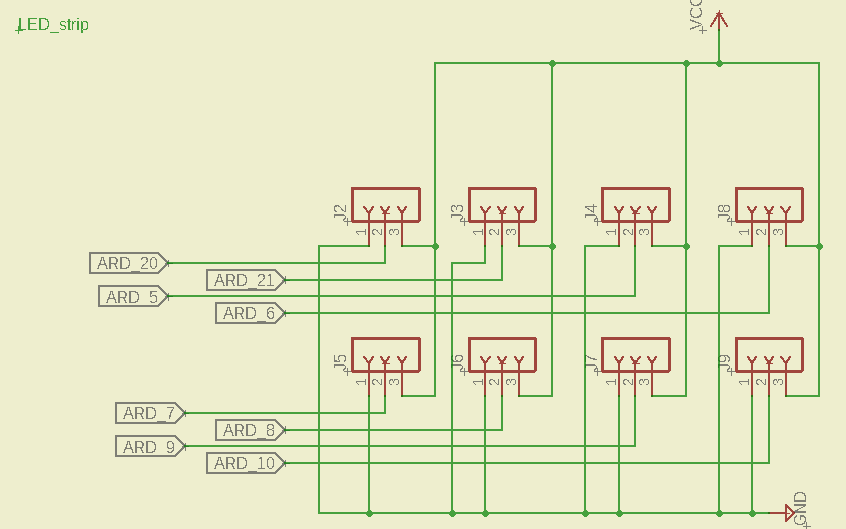
there are headers for every led strip and each is connected to microcontroller data pins and VCC and ground
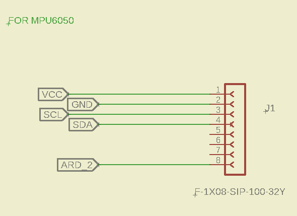
the input for the circuit is the accelerometer module which detects the movement of the cup to control led movement
coding
accelerometer and gyro
the project is based on the accelerometer and gyro. i am using a MPU-6050 Module GY-521 3 Axis Acceleration Gyroscope 6 DOF Module. this module has 3-axis accelerometer and 3-axis gyro meaning it can give me 6 degrees of motion sensing. i am using it to find the pitch, yaw and roll which are values that tell me how the object is moving in space. i need this information to detect cup movement and find how everything is moving.
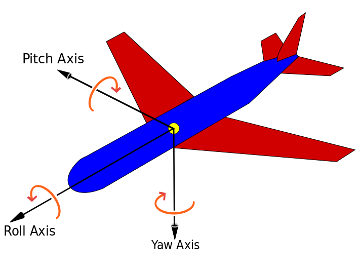
the yaw and pitch will be used in the code later to calculate how much the liquid is tilted.
first i start with testing using a ready made microcontroller to find how it works and how to read the values. i used NI myrio for first testing
Addressable RGB LED
Individually addressable LED’s are just as the name implies. Each individual LED in the series has it’s own control circuit built right in. This allows you to communicate with each LED digitally using it’s “address” to control it individually of the others
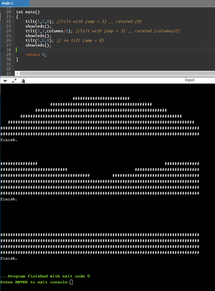
Test code
so i made this to test my concept code of the LEDS:
https://www.onlinegdb.com/SJKRxIGpS
final code
            // NeoPixel Ring simple sketch (c) 2013 Shae Erisson
            // released under the GPLv3 license to match the rest of the AdaFruit NeoPixel library
            #include <Adafruit_NeoPixel.h>
            #include <Wire.h>
            //#include "MPU6050.h"
            #include "MPU6050_6Axis_MotionApps20.h"

            #define INTERRUPT_PIN 2 // use pin 2 on Arduino Uno & most boards
            #define OUTPUT_READABLE_YAWPITCHROLL
            //#define OUTPUT_READABLE_EULER

            MPU6050 mpu;


            int16_t ax, ay, az;
            int16_t gx, gy, gz;


            // MPU control/status vars
            bool dmpReady = false;  // set true if DMP init was successful
            uint8_t mpuIntStatus;   // holds actual interrupt status byte from MPU
            uint8_t devStatus;      // return status after each device operation (0 = success, !0 = error)
            uint16_t packetSize;    // expected DMP packet size (default is 42 bytes)
            uint16_t fifoCount;     // count of all bytes currently in FIFO
            uint8_t fifoBuffer[64]; // FIFO storage buffer

            // orientation/motion vars
            Quaternion q;           // [w, x, y, z]         quaternion container
            VectorInt16 aa;         // [x, y, z]            accel sensor measurements
            VectorInt16 aaReal;     // [x, y, z]            gravity-free accel sensor measurements
            VectorInt16 aaWorld;    // [x, y, z]            world-frame accel sensor measurements
            VectorFloat gravity;    // [x, y, z]            gravity vector
            float euler[3];         // [psi, theta, phi]    Euler angle container
            float ypr[3];           // [yaw, pitch, roll]   yaw/pitch/roll container and gravity vector
            float myypr[3];
            float old_ypr[3];
            // packet structure for InvenSense teapot demo
            uint8_t teapotPacket[14] = { '$', 0x02, 0,0, 0,0, 0,0, 0,0, 0x00, 0x00, '\r', '\n' };


            // ================================================================
            // ===               INTERRUPT DETECTION ROUTINE                ===
            // ================================================================

            volatile bool mpuInterrupt = false;     // indicates whether MPU interrupt pin has gone high
            void dmpDataReady() {
                mpuInterrupt = true;
            }


            #ifdef __AVR__
              #include <avr/power.h>
            #endif

            // Which pin on the Arduino is connected to the NeoPixels?
            // On a Trinket or Gemma we suggest changing this to 1


            #define PIN0            20
            #define PIN1            21
            #define PIN2            5
            #define PIN3            6
            #define PIN4            7
            #define PIN5            8
            #define PIN6            9
            #define PIN7            10

            #define PIN_DETECT_CHARGING 4

            // How many NeoPixels are attached to the Arduino?
            #define NUMPIXELS      17
            #define PIXELS_HEIGHT   6
            // When we setup the NeoPixel library, we tell it how many pixels, and which pin to use to send signals.
            // Note that for older NeoPixel strips you might need to change the third parameter--see the strandtest
            // example for more information on possible values.
            Adafruit_NeoPixel pixels0 = Adafruit_NeoPixel(NUMPIXELS, PIN0, NEO_GRB + NEO_KHZ800);
            Adafruit_NeoPixel pixels1 = Adafruit_NeoPixel(NUMPIXELS, PIN1, NEO_GRB + NEO_KHZ800);
            Adafruit_NeoPixel pixels2 = Adafruit_NeoPixel(NUMPIXELS, PIN2, NEO_GRB + NEO_KHZ800);
            Adafruit_NeoPixel pixels3 = Adafruit_NeoPixel(NUMPIXELS, PIN3, NEO_GRB + NEO_KHZ800);
            Adafruit_NeoPixel pixels4 = Adafruit_NeoPixel(NUMPIXELS, PIN4, NEO_GRB + NEO_KHZ800);
            Adafruit_NeoPixel pixels5 = Adafruit_NeoPixel(NUMPIXELS, PIN5, NEO_GRB + NEO_KHZ800);
            //Adafruit_NeoPixel pixels6 = Adafruit_NeoPixel(NUMPIXELS, PIN6, NEO_GRB + NEO_KHZ800);
            //Adafruit_NeoPixel pixels7 = Adafruit_NeoPixel(NUMPIXELS, PIN7, NEO_GRB + NEO_KHZ800);
            //Adafruit_NeoPixel pixels8 = Adafruit_NeoPixel(NUMPIXELS, PIN8, NEO_GRB + NEO_KHZ800);

            int delayval = 0; // delay for half a second

            float liquidlevel = 3;
            int ylevel[PIXELS_HEIGHT][NUMPIXELS];

            float bigZ;

            void setup() {
              // This is for Trinket 5V 16MHz, you can remove these three lines if you are not using a Trinket

            Wire.begin();
             mpu.initialize();
             Serial.begin(38400);
             Serial.println(mpu.testConnection() ? "MPU6050 connection successful" : "MPU6050 connection failed");
              pinMode(INTERRUPT_PIN, INPUT);

               devStatus = mpu.dmpInitialize();
                   // supply your own gyro offsets here, scaled for min sensitivity
                          mpu.setXAccelOffset(153);
                          mpu.setYAccelOffset(657);
                          mpu.setZAccelOffset(2771);
                          mpu.setXGyroOffset(266);
                          mpu.setYGyroOffset(22);
                          mpu.setZGyroOffset(-7);


              if (devStatus == 0) {
                    // turn on the DMP, now that it's ready
                    Serial.println(F("Enabling DMP..."));
                    mpu.setDMPEnabled(true);

                    // enable Arduino interrupt detection
                    Serial.println(F("Enabling interrupt detection (Arduino external interrupt 0)..."));
                    attachInterrupt(0, dmpDataReady, RISING);
                    mpuIntStatus = mpu.getIntStatus();

                    // set our DMP Ready flag so the main loop() function knows it's okay to use it
                    Serial.println(F("DMP ready! Waiting for first interrupt..."));
                    dmpReady = true;

                    // get expected DMP packet size for later comparison
                    packetSize = mpu.dmpGetFIFOPacketSize();
                } else {
                    // ERROR!
                    // 1 = initial memory load failed
                    // 2 = DMP configuration updates failed
                    // (if it's going to break, usually the code will be 1)
                    Serial.print(F("DMP Initialization failed (code "));
                    Serial.print(devStatus);
                    Serial.println(F(")"));
            }

            #if defined (__AVR_ATtiny85__)
              if (F_CPU == 16000000) clock_prescale_set(clock_div_1);
            #endif
              // End of trinket special code

              pixels0.begin(); // This initializes the NeoPixel library.
              pixels1.begin(); // This initializes the NeoPixel library.
              pixels2.begin(); // This initializes the NeoPixel library.
              pixels3.begin(); // This initializes the NeoPixel library.
              pixels4.begin(); // This initializes the NeoPixel library.
              pixels5.begin(); // This initializes the NeoPixel library.
              //pixels6.begin(); // This initializes the NeoPixel library.
              //pixels7.begin(); // This initializes the NeoPixel library.
              //pixels8.begin(); // This initializes the NeoPixel library.

              pinMode(PIN_DETECT_CHARGING,INPUT); //this is detect charge
            }


            void battery_charging(){
              static long bt_timer = 0;
              static uint8_t bt_level = 0;
              if (millis() - bt_timer > (250)){ // 30 fps
                    bt_timer = millis();
                    if (bt_level++ > PIXELS_HEIGHT)
                      bt_level = 0;
                    for (int i=0; i<PIXELS_HEIGHT; i++)
                    {
                           for (int j=0; j<NUMPIXELS; j++)
                           {
                                   if (j > 1 && j < 4 && bt_level > i)
                                   {ylevel[i][j] = pixels0.Color(0,2,0);}
                                   else
                                   {ylevel[i][j] = pixels0.Color(0,0,0) ;}

                           }
                    }
              }

            }

            void no_charging(float* vals){
              static long bt_timer = 0;
              static uint8_t bt_level = 0;
              if (millis() - bt_timer > (0)){ // 30 fps
                    bt_timer = millis();

                      for (int i=0; i<PIXELS_HEIGHT; i++)
                      {
                       for (int j=0; j<NUMPIXELS; j++)
                       {
                         float angle_amplitude = vals[0];
                         float xx = liquidlevel + ((float)angle_amplitude * abs(sin(    (PI* (float)rotation/(float)NUMPIXELS )     + 2 * PI * ((float)i/((float)NUMPIXELS*2.0f)))) - (float)angle_amplitude/2.0f  );
                         //float xx = liquidlevel + (   sqrt(    pow(vals[1],2) + pow(vals[2],2)     ) *0.5  )* abs(sin(vals[0]*4 +  PI * (1.0f/(NUMPIXELS-1)) * j));    //sin(PI* 1/17 * i));
                         //float xx = liquidlevel + (   3  )* abs(sin(vals[0]*3 +  PI * (1.0f/(NUMPIXELS-1)) * j));    //sin(PI* 1/17 * i));
                         if (xx > ((float)i+0.1f))
                         {ylevel[i][j] = pixels0.Color(0,1,2);}
                         else
                         {ylevel[i][j] = pixels0.Color(0,0,0) ;}

                       }
                      }

              }
            }

            bool fifo_of=false;
            void loop() {
                 // if programming failed, don't try to do anything
                //if (!dmpReady) return;

                if (dmpReady)
                        {
                          // wait for MPU interrupt or extra packet(s) available
                        while (!mpuInterrupt && fifoCount < packetSize) {
                        }

                        // reset interrupt flag and get INT_STATUS byte
                        mpuInterrupt = false;
                        mpuIntStatus = mpu.getIntStatus();

                        // get current FIFO count
                        fifoCount = mpu.getFIFOCount();

                        // check for overflow (this should never happen unless our code is too inefficient)
                        if ((mpuIntStatus & 0x10) || fifoCount > 1000) {
                            // reset so we can continue cleanly
                            mpu.resetFIFO();
                            //Serial.println(F("FIFO overflow!"));


                        // otherwise, check for DMP data ready interrupt (this should happen frequently)
                        } else if (mpuIntStatus & 0x02) {


                                            // wait for correct available data length, should be a VERY short wait
                                            while (fifoCount < packetSize) fifoCount = mpu.getFIFOCount();

                                            // read a packet from FIFO
                                            mpu.getFIFOBytes(fifoBuffer, packetSize);

                                            // track FIFO count here in case there is > 1 packet available
                                            // (this lets us immediately read more without waiting for an interrupt)
                                            fifoCount -= packetSize;
                                            #ifdef OUTPUT_READABLE_YAWPITCHROLL

                                                  if (digitalRead(PIN_DETECT_CHARGING))
                                                  {
                                                    battery_charging(); //update screen buffer as charging ..
                                                  }else{
                                                      //calculate then update screen buffer:
                                                      // display Euler angles in degrees
                                                        mpu.dmpGetQuaternion(&q, fifoBuffer);
                                                        mpu.dmpGetGravity(&gravity, &q);
                                                        mpu.dmpGetYawPitchRoll(ypr, &q, &gravity);
                                                        no_charging(ypr);
                                                  }

                                                    showleds(); //update cup screen :)
                                            #endif
                        }
                }


            //delay(delayval); // Delay for a period of time (in milliseconds).
            }


            void showleds()
            {
               for (int m = 0; m< NUMPIXELS; m++)
                {

                       pixels0.setPixelColor(m, ylevel[0][m]); // Moderately bright green color.
                       pixels1.setPixelColor(m, ylevel[1][m]); // Moderately bright green color.
                       pixels2.setPixelColor(m, ylevel[2][m]); // Moderately bright green color.
                       pixels3.setPixelColor(m, ylevel[3][m]); // Moderately bright green color.
                       pixels4.setPixelColor(m, ylevel[4][m]); // Moderately bright green color.
                       pixels5.setPixelColor(m, ylevel[5][m]); // Moderately bright green color.
                       //pixels6.setPixelColor(m, ylevel[6][m]); // Moderately bright green color.

                }
               pixels0.show(); // This sends the updated pixel color to the hardware.
               pixels1.show(); // This sends the updated pixel color to the hardware.
               pixels2.show(); // This sends the updated pixel color to the hardware.
               pixels3.show(); // This sends the updated pixel color to the hardware.
               pixels4.show(); // This sends the updated pixel color to the hardware.
               pixels5.show(); // This sends the updated pixel color to the hardware.
               //pixels6.show(); // This sends the updated pixel color to the hardware.

            }