in this week assignment is to make AVR ICSP programmer
ICSP stands for in circuit serial programming
it uses SPI pin of a microcontroller to pragram it .. this is common AVR icsp pins:
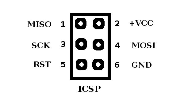
in this page i’ll show my attemps to make AVR programmer using both Attiny45 and Attiny44 microcontrollers
Fab Tiny star - mini:

- Attiny45
-> microcontroller - 1KΩ resistor
-> current limit led - 1.5kΩ resistors
-> pull-up resistor for data - - 500Ω resistors
-> current limit led - 49Ω resistors
-> current limit - protection for pins - 3.3v zener diodes
-> 5v usb to 3.3v mcu Input pins - red LED
-> 1x power + 1x data blink - 100nF capacitor
-> decoupling for mcu - 2x3 pin header
-> programming header

Milling:
to start with i downloaded traces and outline cut png files of fab tiny star mini:


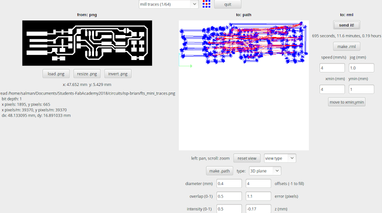 as you can see the following in the settings:
- diameter
0.4 mmwhich is the drill-bit size 1⁄64” - offset i set this to
1with this bit as it will cut only once to save time and drill life - intensity goes from 0 to 1 which the program extinguish between black and white .. i prefer the default 0.5 which is in middle between black and white
- z(mm) is how much the machine moves in z-axis to cut .. for milling i prefer 0.1mm when the z-axis calibrated well..
after setting the path parameters .. i set the right corner parameters (jog, speed, x,y): i set speed to 3mm x and y really depend on where i place the PCB to i always calibrate that moving the drill to the corner of PCB
Soldering:
i set temperature of the solder iron to 300-350 celsius degree
i soldered SMD components before but very few times, here is the progress of soldering
the components in GIF image..
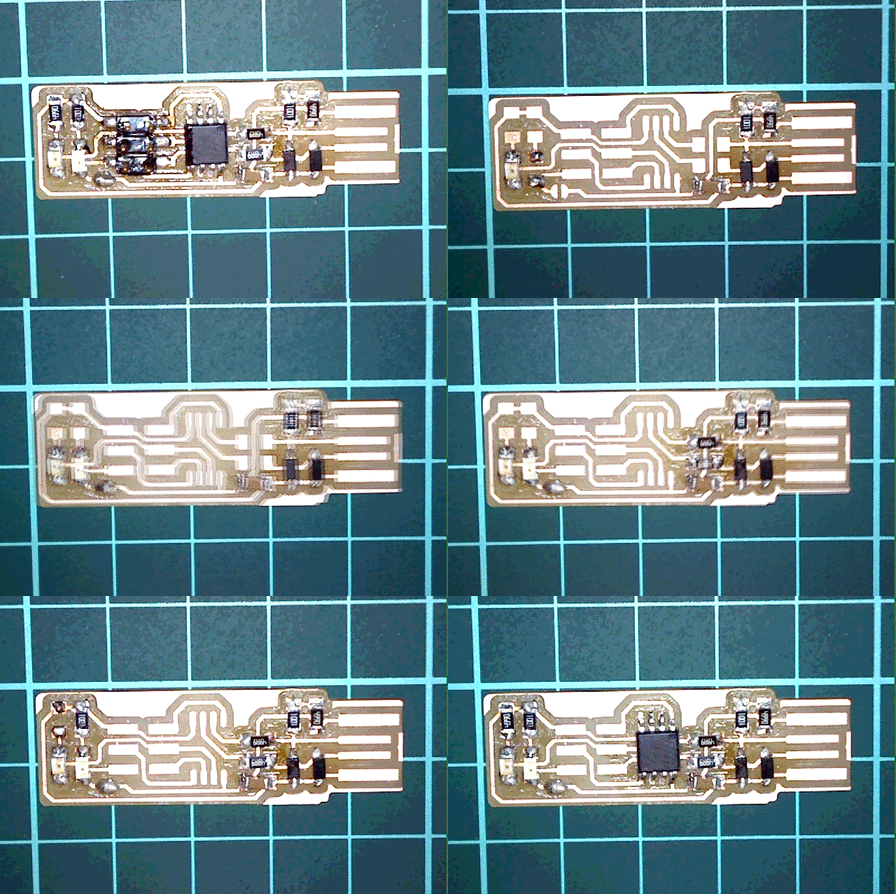 Note: used imagemagick to create gif image
although it stick in second frame, i dont know why..
note:pictures were taken by digital microscope which is really cool ..
Programming:
to program the microcontroller we need a programmer which basicly convert the usb protocol to the
icsp ..
to flash the compiled program we use Avrdude which talks to the programmer
in order to make the program i just downloaded fts firmware v1
there are several commands in the make file and it well documented:

so i just compiled and flashed the mcu
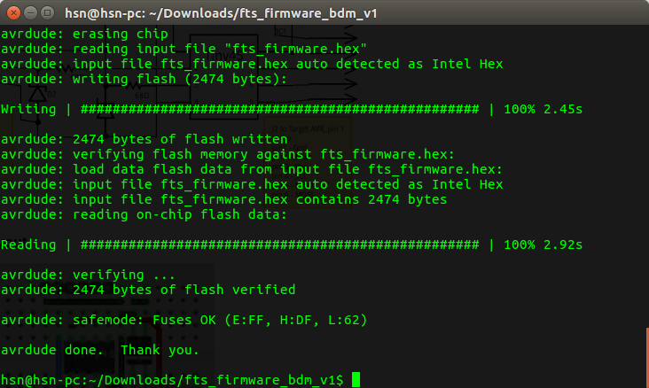 set the fuses:
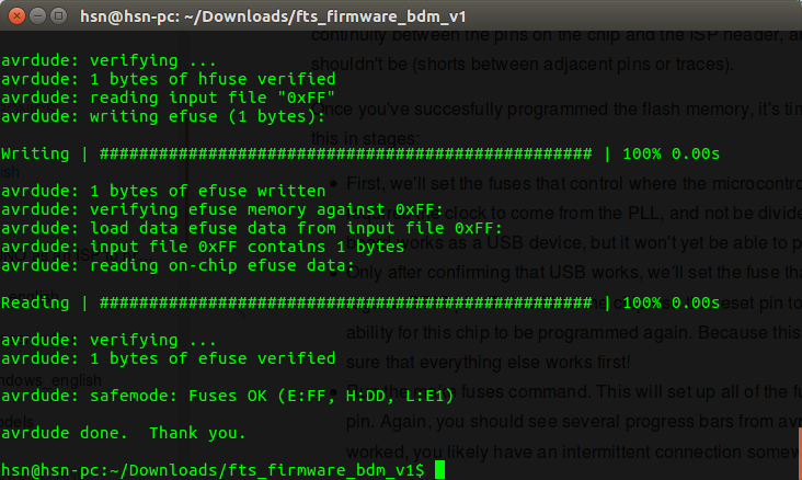
after all of that i just unplugged the programmer and the new programmer ..
but i couldnt find it in the usb list using lsusb ..
when i check dmesg it shows that the device is “low speed” ..
i looked into the solder in Dmm using continuety test nothing seems wrong in the connection ..
i thought that its because the make file uses the f_cpu of 16.5 MHz which doesnt seems right ..
so i tried to upload blink 1 sec program …
int main()
{
    .
    .
    .
     DDRB = 0b00010000;
    for(;;){                /* main event loop /
        DBG1(0x02, 0, 0);   / debug output: main loop iterates */
        wdt_reset();
        usbPoll();
    PORTB ^= 0b00010000;
    _delay_ms(1000);
    }
}
the blink was working which means the problem is not in clock speed…
so i know the problem source is not in clock speed .. or fuses that are related to the clock
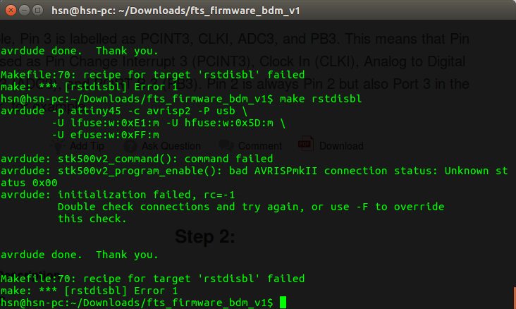
when i was testing different things i did used this command
make rstdisbl
which set High fuse to 0x5D
which basicly disables the reset pin in order to use it for the mcu as io pin ..
i couldnt program it again later after i discovered what i ve done …
Start over:
i really couldnt find the issue so i started milling different circuit ..
followed same procedures ..
and flashed the MCU .. set the fuses ..
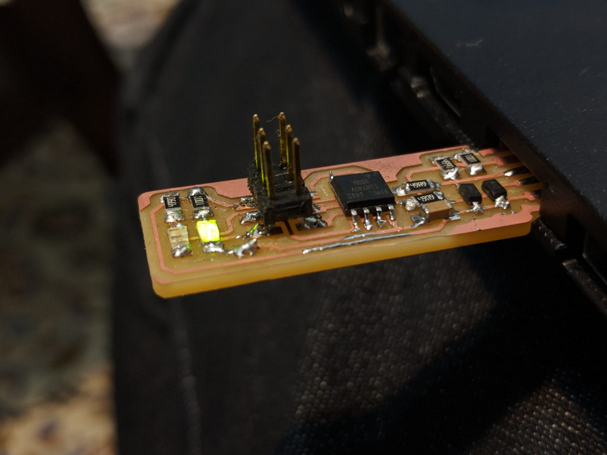
had the same problem but then i did also redid the soldering for the USB pinout and tried again and i got it running..

What was wrong?
i am not sure why it did not work the first time i made it. i followed the exact same way the second time and it worked. but i have a guess. the attiny i used the first time was from a batch that was in the lab since 2015 (i checked the date on the bag) and the bag it was in was open. i think maybe it is possible that the microcontroller i used the first time was damaged becuase it is really old and was exposed to air moist. the second time i used a newer attiny that we just ordered from digikey so maybe that could be the reason it worked.