input week
the assignment this week is to do a grup[ project of testing an analog sensor which was done here:
group project link
and to Measure something: add a sensor to a microcontroller board that you have designed and read it
there are different types of sensors. a sensoer is a device that converts signals from one energy domain to electrical domain. means it takes something like tempreture or something and turns it to electrical signals we can read with a micrcontroller.
line follow color detect sensor
for the first input devices i them on my electronic design week PCB becuase i spend a long time making it and had to re do it twice so didnt have time, but i did make a circuit later. you can see it at the end of this page.
first sensor i used was a sensor module for use with color detenction. it is a infrared sensor designed primarily to allow wheeled robots to follow lines. The sensor is comprised of an infrared transmitter/receiver pair emitting a certain IR frequency to detect reflectivity with precision.
the way this works is by emiting infrared radiation from the transmitter and then the receiver then responds to the IR waves that get reflected from the reflecting surface. The IR waves are usually absorbed by the black colored surface and reflect from the white color surface. this is how it know which color is white and what is black.
technically the module turns it to digital high and digital low (either almost 0 volt or almost 5 volt) . but i wanted to see the raw analog value to know what values i am getting and how it changes with differant surfaces.
analog to digital converter is is a system that converts an analog signal to a digital signal. not all attiny44 pins can convert from analog to digital.

only the pins marked with (ADC) can convert from analog to digital. i connected the module to PA6. the module only needs three connections. vcc, ground and signal pin.
how analog to digital convertor works is reading the voltage applied to the pin and giving it a digital value accordingly.

attiny44 has 10 bit analog to digital converots which means it can detect 1,024 (2^10) discrete analog levels.
5 volt = 1023 reading
0 volt = 0 reading
2.5 volt = 512 reading
and everything in between.
i got raw reading first and saw the values when i change from white to black

then added if statement to determine white and black.


the code used is
#include
#define RX PA1
#define TX PA0
#define sensePin PA6
SoftwareSerial xSerial(RX, TX);
int sensorInput; //The variable we will use to store the sensor input
void setup() {

xSerial.begin(9600);
pinMode (sensePin, INPUT);
}
void loop() {
sensorInput = analogRead(sensePin); //read the analog sensor data
xSerial.print(” Raw reading:“);
xSerial.println(sensorInput);
if (sensorInput < 200){
   xSerial.println(“white”);
}
else
{
  xSerial.println(“black”);
}
delay(100);
}
video demo
Ultrasonic sensor
the second sensor i used is HC-SR04 ultrasonic sensor.

Ultrasonic sensors work by sending out a sound wave at a frequency above the range of human hearing. The transducer of the sensor acts as a microphone to receive and send the ultrasonic sound. The sensor determines the distance to a target by measuring time lapses between the sending and receiving of the ultrasonic pulse.
there is trigger pin that sends the signal and echo that recieves the signal to do the calculations. i wrote some code to upload to my circuit but got this problem.
#include
#define trigPin PA6
#define echoPin PA5
SoftwareSerial mySerial(PA1, PA0);

// defines variables
long duration;
int distance;
void setup() {
pinMode(trigPin, OUTPUT); // Sets the trigPin as an Output
pinMode(echoPin, INPUT); // Sets the echoPin as an Input
mySerial.begin(9600);
  //mySerial.println("hi there");
}
void loop() {
// Clears the trigPin
digitalWrite(trigPin, LOW);
delayMicroseconds(2);
// Sets the trigPin on HIGH state for 10 micro seconds
digitalWrite(trigPin, HIGH);
delayMicroseconds(10);
digitalWrite(trigPin, LOW);
// Reads the echoPin, returns the sound wave travel time in microseconds
duration = pulseIn(echoPin, HIGH);
// Calculating the distance
distance= duration*0.034/2;
mySerial.println(distance);
}

there is nothing that can be removed from the code to save memory. everything here is important. after looking i found out that software serial library takes a lot of memory. i need software serial to communicate with the board and display the sensor value to make sure i am getting it right.

i tried a trick which is to save the value in char and then send it to serial print becuase it takes less memory than converting it to ASCII in the serial print function. ASCII is the text that is redable by humans. values are saved as integer but to show on serial monitor it is converted to ASCII.


it looks like a lot of random charachters but when i copy it and put it in char to ASCII converter it shows that its actually numbers.


but the problem here is that i cant know if the values are right or wrong.
i tried something else. to change to byte and then output that

i get numbers and its showing correct distance

#include
#define trigPin PA6
#define echoPin PA5
SoftwareSerial mySerial(PA1, PA0);

// defines variables
long duration;
int distance;
void setup() {
pinMode(trigPin, OUTPUT); // Sets the trigPin as an Output
pinMode(echoPin, INPUT); // Sets the echoPin as an Input
mySerial.begin(9600);
  //mySerial.println("hi there");
}
void loop() {
// Clears the trigPin
digitalWrite(trigPin, LOW);
delayMicroseconds(2);
// Sets the trigPin on HIGH state for 10 micro seconds
digitalWrite(trigPin, HIGH);
delayMicroseconds(10);
digitalWrite(trigPin, LOW);
// Reads the echoPin, returns the sound wave travel time in microseconds
duration = pulseIn(echoPin, HIGH);
// Calculating the distance
distance= duration*0.034/2;
// Prints the distance on the Serial Monitor
//char C[] = distance;
//mySerial.print(C);
//char y = distance;
//mySerial.print(y);
byte ASCIIvalue = distance;
mySerial.println(ASCIIvalue);
//mySerial.println(distance);
}
video demo
Additional board
i wanted to make 1 board that has general connectors to test the microcontroller
and having access to the pins easily ..
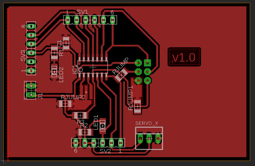
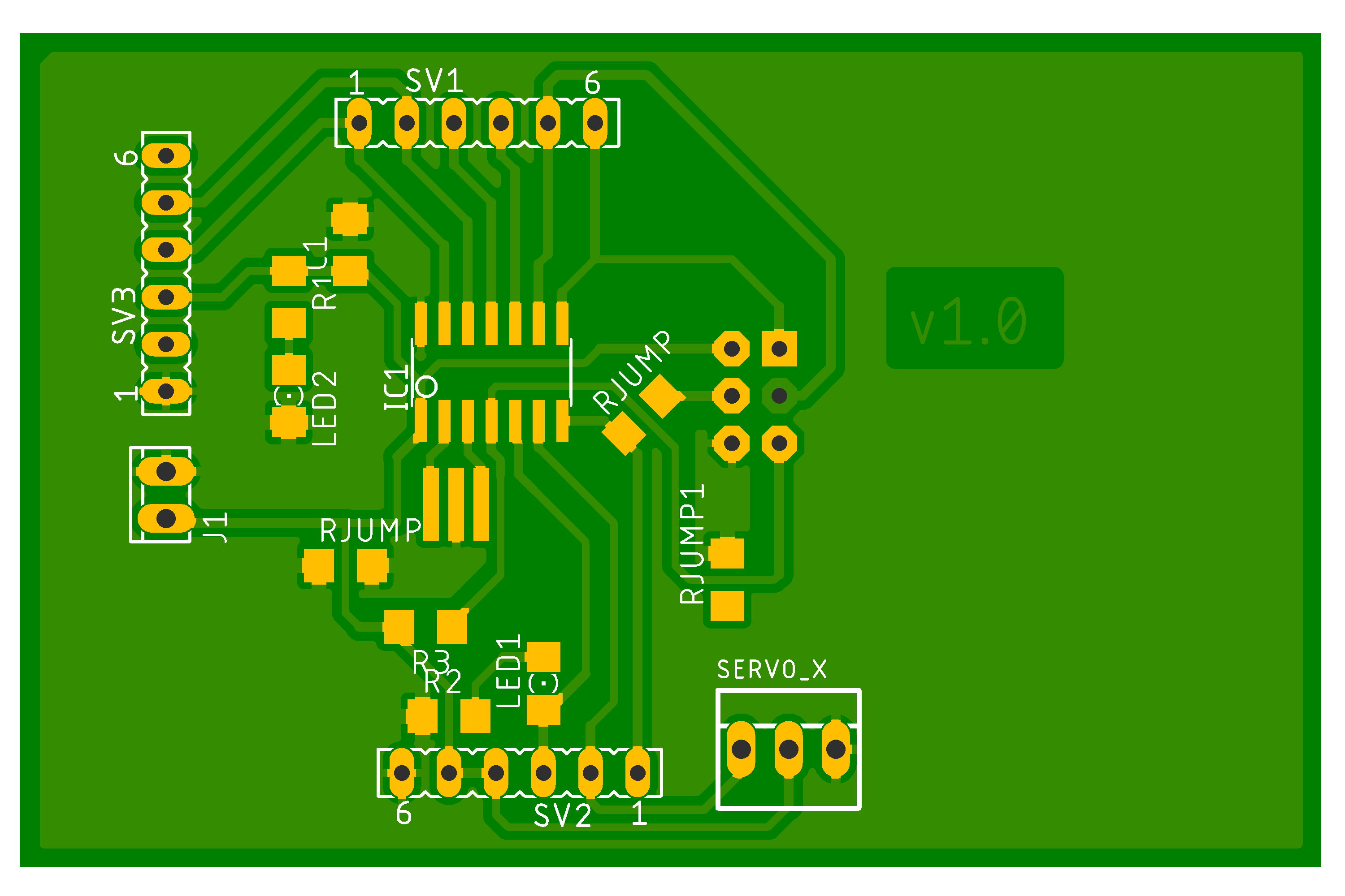
i started eagle and designed this board i call it:
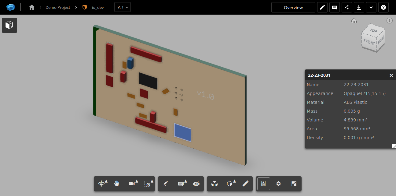
IO board which is input/output board ..
The design was made by eagle

this board has the following features:
- microcontroller Attiny44 with 20Mhz Xtal oscillator
- LED indicator for power on
- Servo connector (GND, Vcc, PA7)
- connector 1 (GND, Vcc, Vcc, PB2, PA7, PA6)
- connector 2 (PA5, PA4, PA3, PA2, PA1, PA0)
- Connector 3 is FTDI interface
- GND, NC, Vcc, PA0
TX, PA1Rx
- GND, NC, Vcc, PA0
- LED indicator for PB2 (good for blink)
PCB design:


 The board can be used for general purpose Development…
other than input devices used in this week, i will use a gyro in final project.

