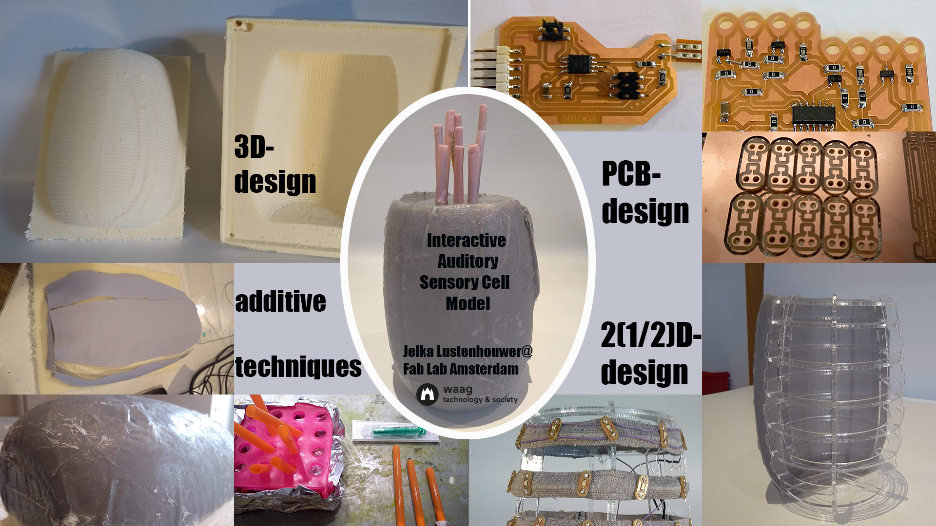
Final Project
All the final files
Fusion files for mold and skeleton AI files for cotton pieces and skeleton Eagle files for bridge, nodes and LED buttons PNG files for bridge, nodes and LED buttons Coding files for network
A fysical model of an auditory sensory hair cell
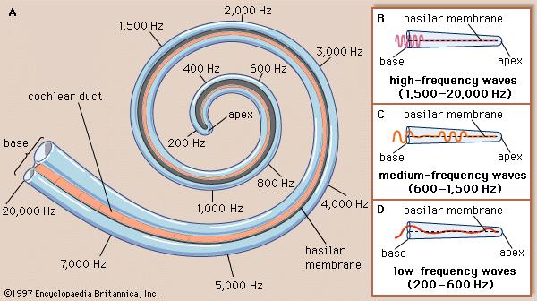
Biology is all around you, so most students and pupils can imagine populations, organisms and organs. But from the cellular level on, things get more and more abstract. But life on the cellular and molecular level is at least as beautifull and amazing as it is on the level of organisms and up. To show this I will make a fysical model of an auditory sensory hair cell. The Theoretical and Computational Biophysics Group of the University of Illinois-Urbana has a great page on the moleculair base of hearing. The idea of the hair cel is that it has hair like structures, sterocilia, that are bend by the pressure of sound waves. The spot where the hair cell is in the Cochlea membrane defines what 'tone' the brain makes of it. High pitch tones (20.000 Hz) at the broad base of the Cochlea, low tones (200 Hz)in the narrow apex. See the picture I got from https://biology.stackexchange.com.
The sterocilia are interconnected with wire-like molecules that, when the cilia are bend, actually mechanically open an ion gate that lets in Potassium ions and that in turn opens up calcium channels in the cell membrane.
The plan
To make a fysical model of the auditory sensory hair cell. I imagine it wil be as big as a hand. The sterocilia could be made of silicone. The interconnecting molecules can be fabric stretch sensors. I'm not sure what to make the cell body from. I would like to simulate the changing membrane potential (the ion gates opening) with a circle of light moving along the surface of the cell body. I made a little stop motion video of this signal along the surface of the cell body.
Design, Materials and Components
| Part | Design | Materials and Components |
|---|---|---|
| 1. Cell Body | 3D design a mold and an inner skeleton in Fusion 360 | Foam for the mold, MDF 4mm for the skeleton. Cotton and Epoxy resin for the cell membrane |
| 2. Stereocilia | Either 3D design a mold, use an existing mold like a straw or make them manually. | Bending sensors embedded in silicone stereocilia. |
| 3. Tip links | Finger knit a yarn to embed in the stereocilia | Bending sensors embedded in silicone stereocilia. |
| 4. Top of the cell body | 2D design a lid that holds the stereocilia. | MDF 4mm |
| 5. Serial Network | Design a serial network using Eagle | Copper plates and electronic components |
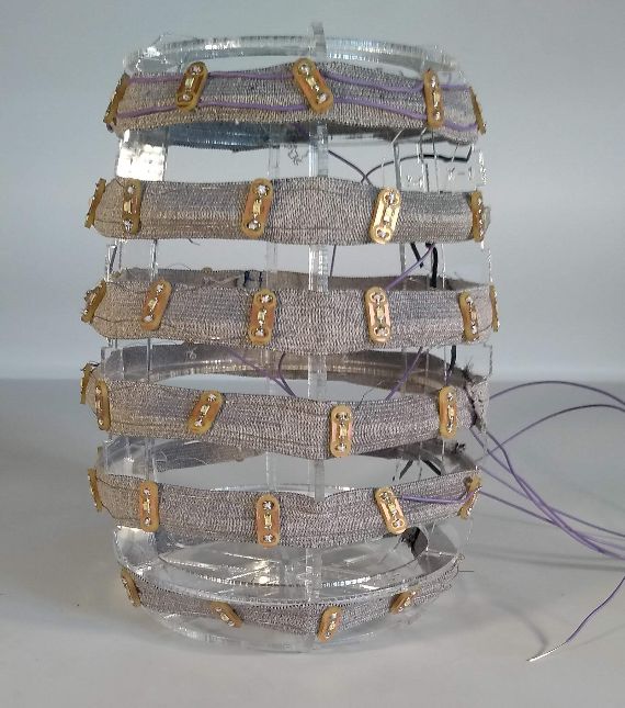
| 6. Changing cell membrane potential | Design LED buttons and sow them on an elastic band that can be mounted on the inner cell skeleton and connected to the network. | Copper plate, 120 LEDs, conductive wire, elastic band. |
| 7. Ion channels | 3D design model of ion (Potassium)channels to embed in the hairs. 3D Design model of Calcium ion channels to glue on the cell membrane. | 3D printer filament |
For each part of the design I will describe the fabrication proces seperately.
Cell Body
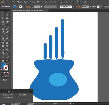
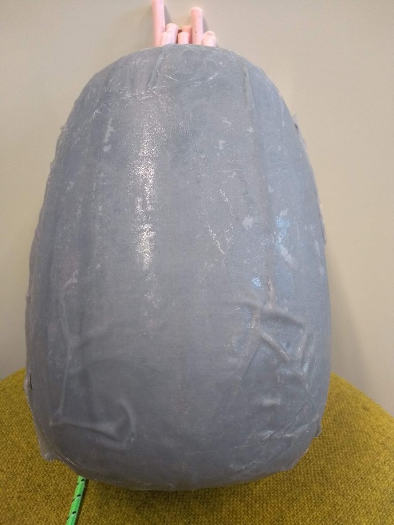
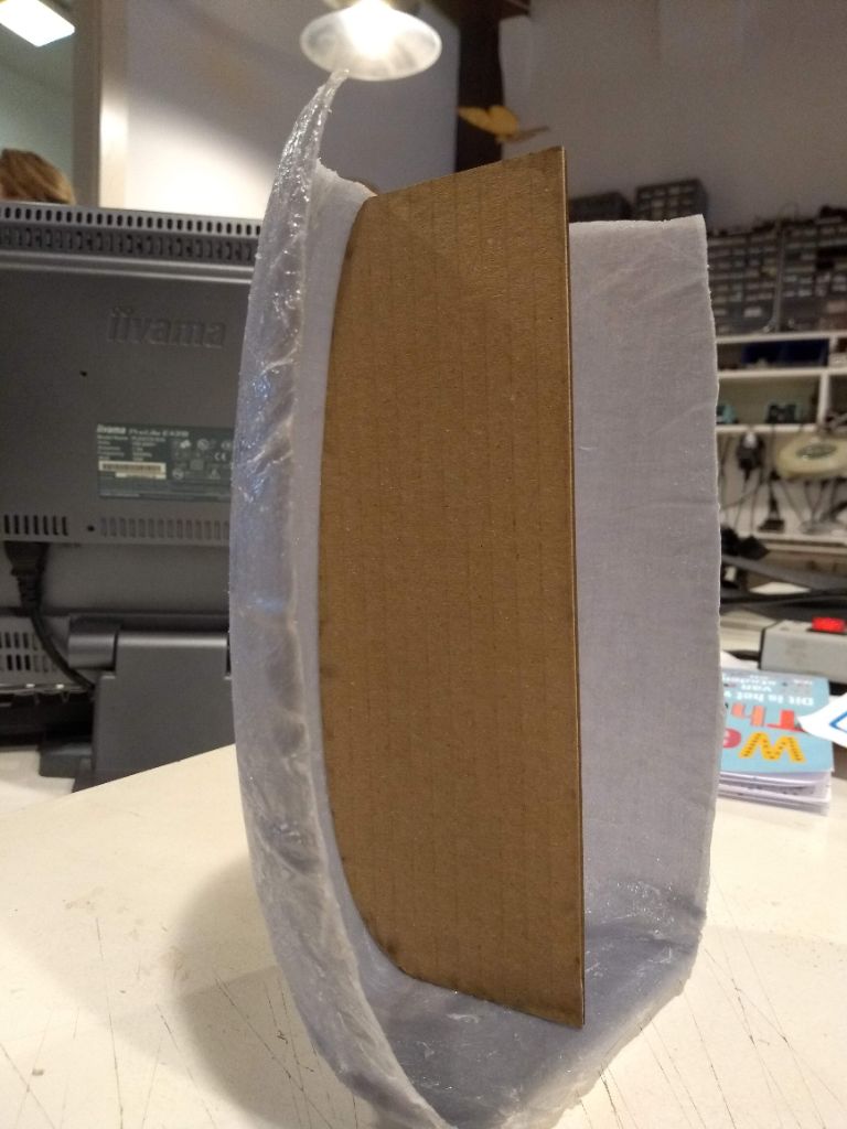
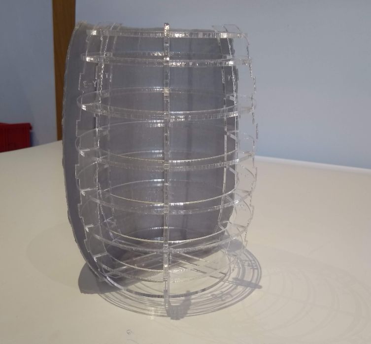
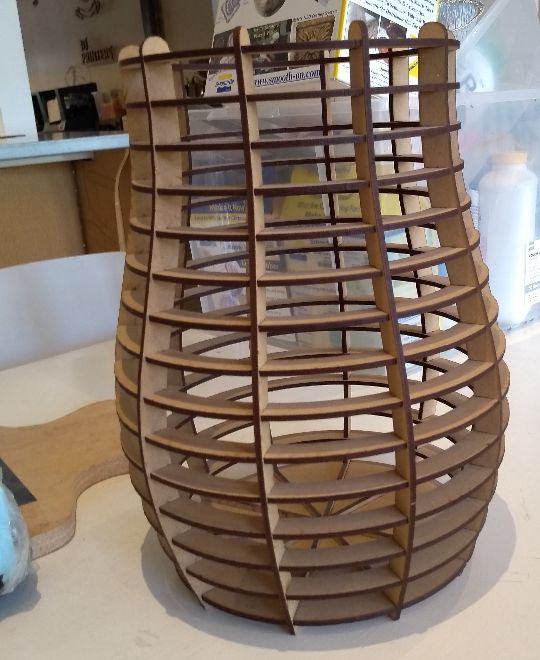 I wil make a lasercut skeleton that will hold the LEDs. The LEDs I will sow on a elastic band. The skeleton will look somewhat like this vase. It will be handy if I make slots in the vertical ribs to keep the elestic band on its place. To cover the cell I will make a shell of a resin/fiber composite. For this I will need to make a mold for one half of the cell and then connect the two halves. How to connect so that I can still open it, I am not sure yet.
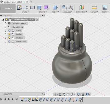
In Week 3: computer aided design I drew a 3D model of a hair cell in Fusion 360 and also a 2D model in Illustrator
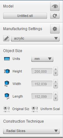
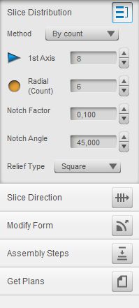
In Week 17: Wild Card I re-designed the cell body for a mold to make a composite of cotton and epoxy. I used the same model to design the shape of the pieces of cotton to cut out with the laser cutter.
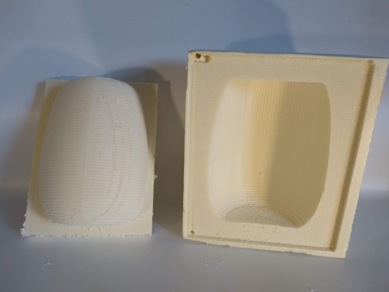
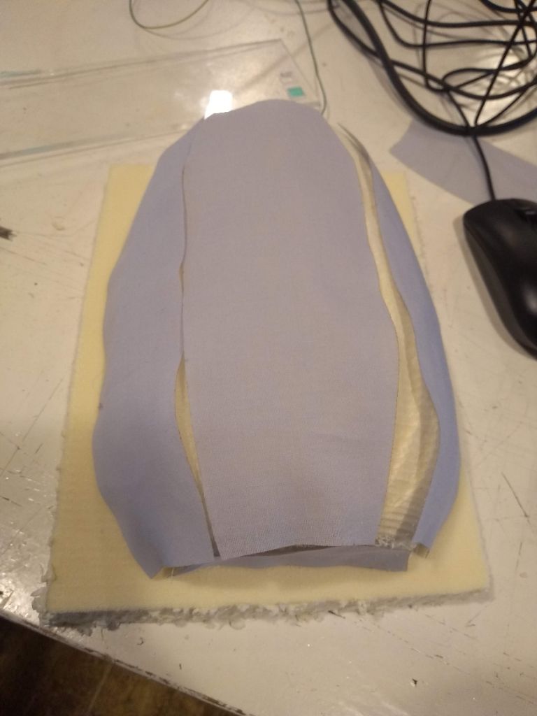
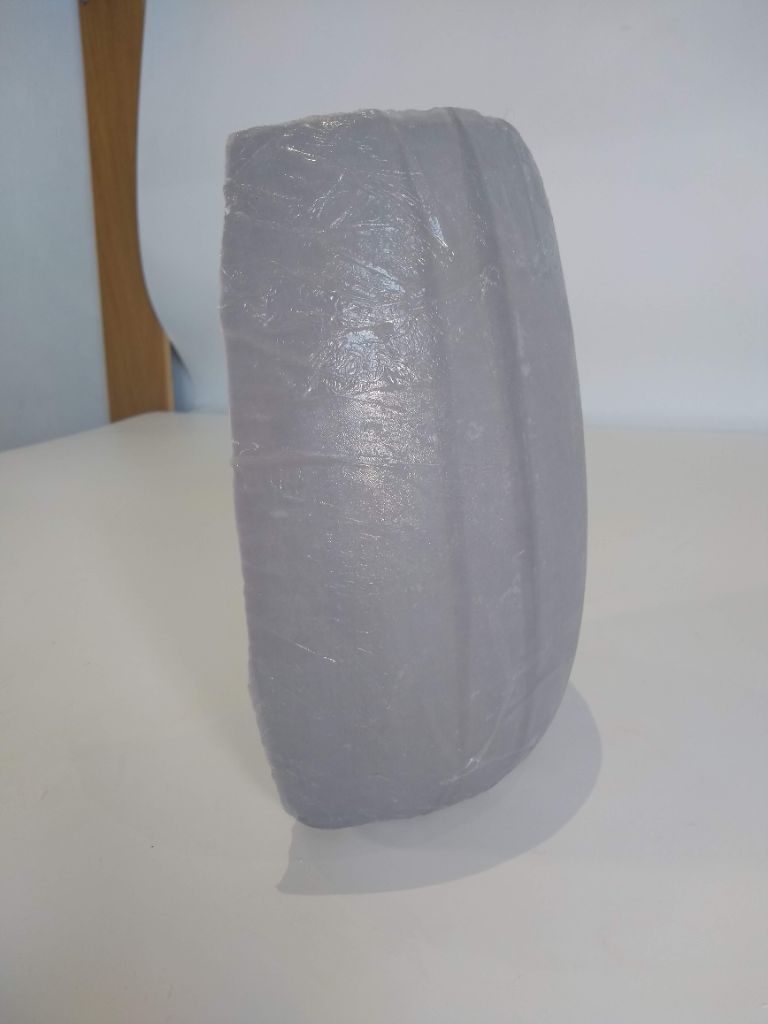
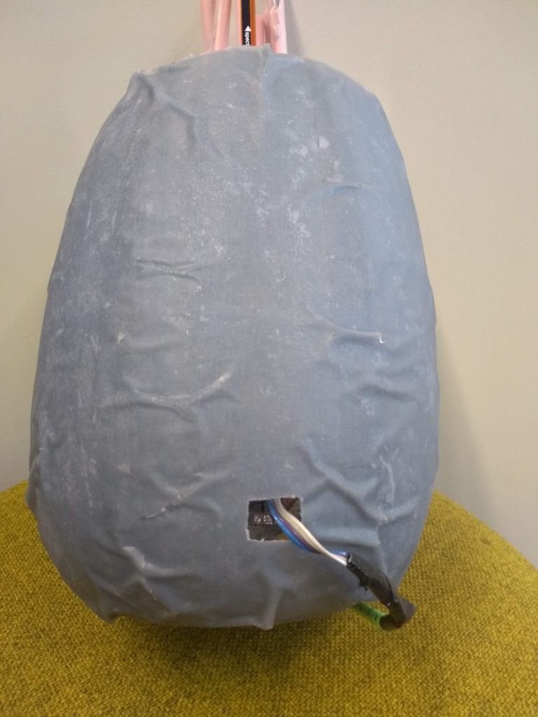
On june 17th I layed up the second half of the cell membrane. Instead of using plastic foil to cover it before it goes into the vacuum bag, I used baking paper this time. The plastic foil made the cell membrane look all wrinkled. I used the design to cut the cotton pieces to cut the baking paper in the same way. I hoped to have a more smooth cover of the mold this way, but I am afraid it didn't help a lot. The second half of the cell body/membrane is even rougher then the first. I will use it as the back of the model. Later, when I decided to add a USB 5V-connection, I made a hole in the back, so the second half of the cell body composite.
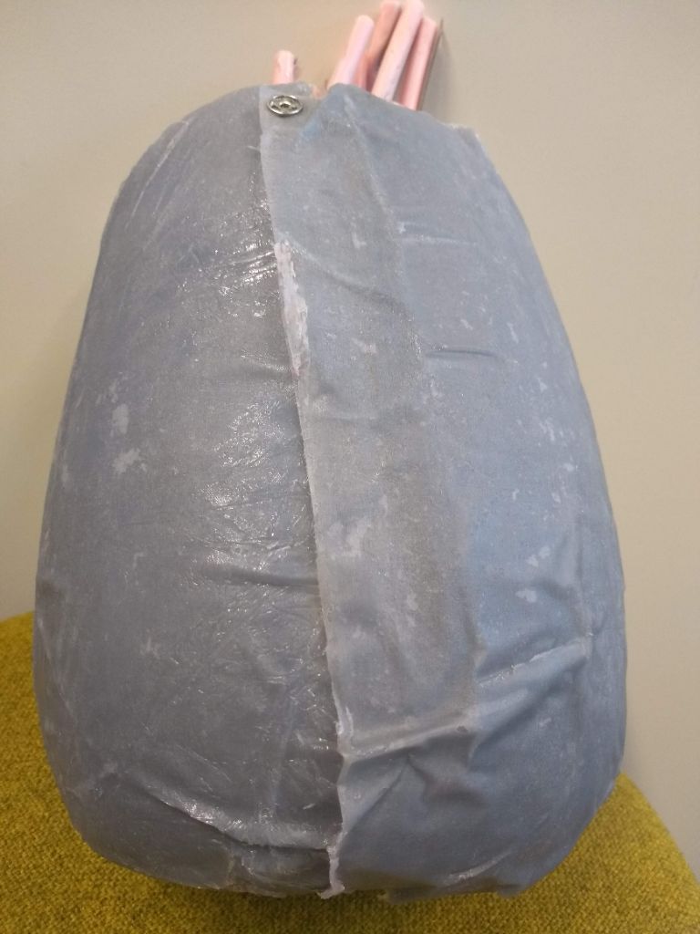
Connecting the two halves of the cell body
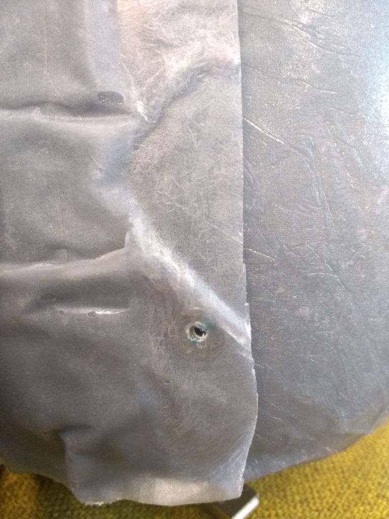
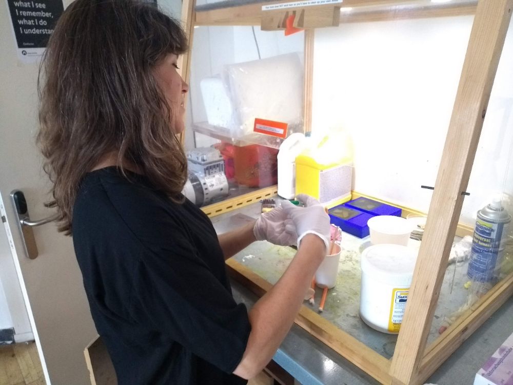
I used snap buttons to connect the two halves. With a piercer I pierced a hole in the composite where the pin of the button should go. Then I used two components glue to glue the buttons on the composite. The glue had a spray and a liquid part. I sprayed on the button and smeared the liquid part on the composite. Use gloves when you do this!I only needed two buttons to connect the two halves firmly. The first button I attached this way, I pinned through the composite. But with the second button I found out this was not needed. So the second button is more blind. (Except that i allready made a hole.)
Cell skeleton
I need do design a inner skeleton in the cell that I can put the strings of LEDs on. In Eagle I again used the same sketch I used for the mold and for the cotton pieces. First I exported the original sketch to a dxf file to laser cut it. This way I could check if an offset was needed. but as you can see from the picture it fits perfectly.
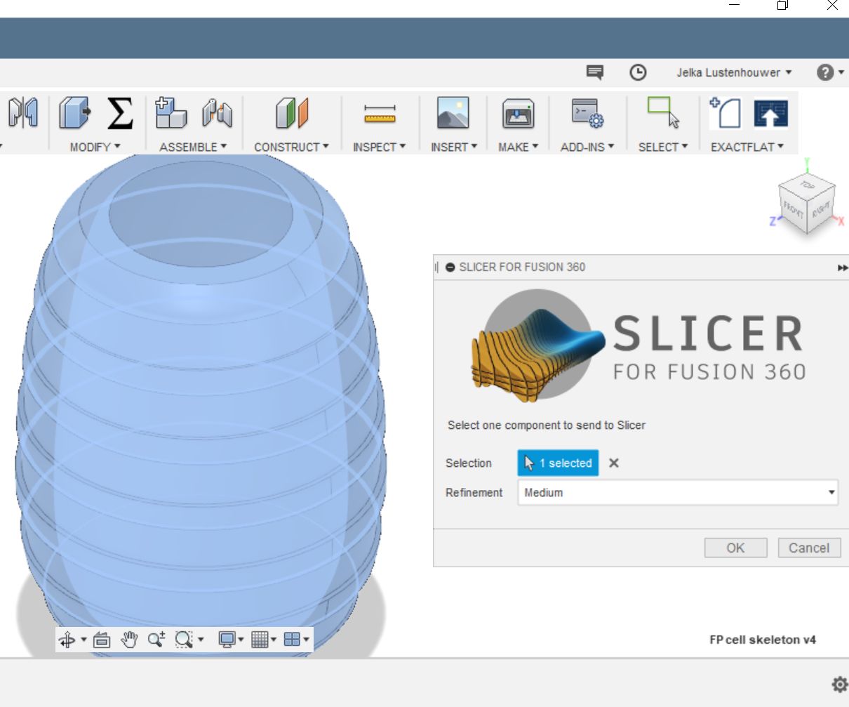
In fusion I drew a hollow body and then used Slicer for Fusion to slice it into a skeleton. This is what I did in Fusion:
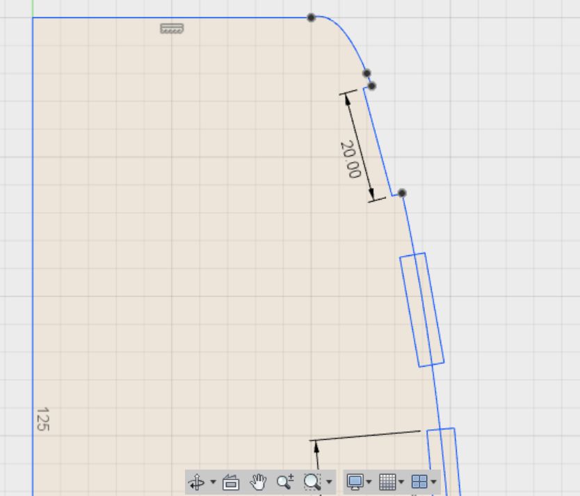
- I drew a rectangle of 20mm, the width of the elastic strap, by 5mm, two time the depth of the LED buttons.
- I moved the the rectangle so that it aligned the curve of the sketch, with the curve going approximaely through the middle of the rectangle. See also the second picture underneath.
- Then under the Sketch button, I chose 'break'. This function makes a break at the junction of two lines. This alowes you to cut away the part of the rectangle that you do not need.
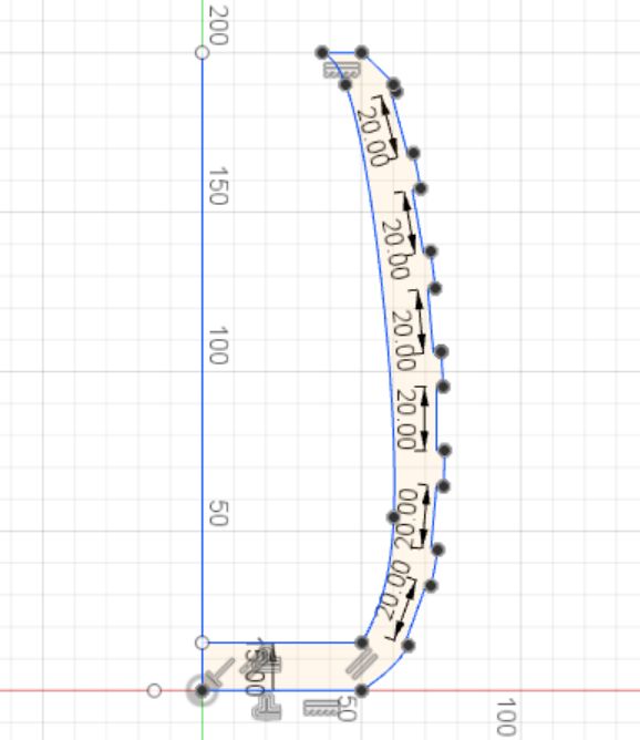
- During this drawing I realized I could never place 12 straps of LEDs on my cell. 6 was the maximum. That was a releave, because I only had 6 and they had coste me (and my friends) hours allready.
- Then I used a copy of the original curve to draw the inner outline of the skeleton. I made it 15mm thick.
- Finally I used the 'revolve' function to make the hollow body I wanted to slice to make the skeleton. (Yikes that sounds creepy)
Then it was time to use the add-in Slicer for Fusion. To get it, you simply click on the Add-Ins icon and the choose Fusion 360 app store. There you search for Slicer and then you can click and install. When you have done that, you can find Slicer for Fusion in the drop down menu of the 'Make' icon. When you click it a window opens. Here you select the 'body' you want to slice. I set the refinement on 'medium'. After that slicer opens and you see the selected body. On the left you can choose what you want slicer to do. See the pictures for the settings and choises I made. You can find a tutorial for Slicer here, but there are many more to find on YouTube.
When you are done you can choose to export the files to a local folder as dxf. If you open this in AI, you first have to clean the file. I had tons of small paths that I had to join manually. But I also found out that it is not necessary to get rid of all of them. The laser cutter can actually deal pretty well with a lot of paths, as long as they have no open spaces in between. After this I saved as CS2 and cut the pieces with Speed 50, Power 100 in the laser cutter.
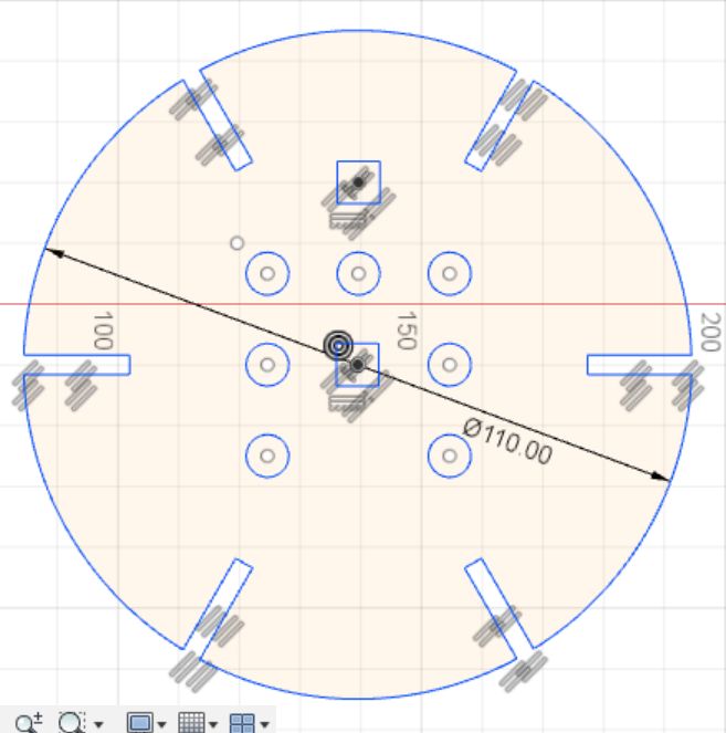
The lid of the cell that holds the stereocilia I did seperately. After the second half of the composite cell body was ready, I measured what the diameter of the lid should be. In Fusion I drew a circle and made a circular pattern of slots that fitted on top of the rest of the skeleton. I drew circles with the diameter of the stereocilia. The two squares you see I drew when I decided to use the bending sensors of the lab, instead of the bending sensors I made myself. See the paragraph on the stereocilia for that.
Stereocilia
May 7th
In my model of a sensory hair cell I will use bend sensors to measure the extend of the bending of the hairs. I will use more then one bending sensor. It would be a shame if you bend the wrong hair, the cell will not respond. I will need at least 9 hairs to make a model that really looks like a hair cell. Am I going to use 9 bend sensors as well? It is a lot, but I would like to aim for it. I would like to embed the bending sensors in silicone.
To test if and how a bending sensor works in silicone, I filled a piece of PVC tube with Mold Max 30 and embedded the bending sensor. From wood I made a plug and put that in a finger of a vinyl glove. This I sprayed with releasing factor. I mixed and poured the silicone. To hold the sensor in its place I used sticky tape to puncture the bending sensor through. All this I placed in a 50 ml laboratory centrifuge tube to keep it upright. I repeated the proces for PMC 121/30 in a longer tube. This way I tested for the length of the tube as well as the material. The PMC has a nice organic color, but is slightly see through. In the model you might be able to see the bending sensors and I am not sure yet if I want this.
It was only later, when I looked up the price of the bending sensors, I realized they are very expensive; 12,95 euro's each. If I want to use 9 sensors, that will be a lot of money.
But then the fantastic Kobakant website showed me this Instructables tutorial how to make my own sticky tape bending sensors. So I ordered Velostat, conductive thread and conductive fabric at the Kiwi Electronics Webshop. With the materials I bought, costing something like 22 euro's I could make 200 bending sensores. Let's hope it works.
June 5th:making and testing bending sensors
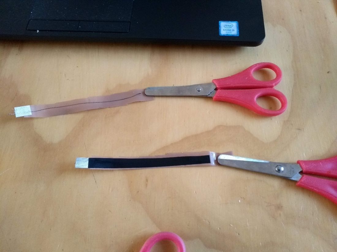
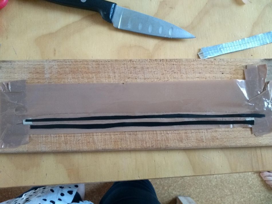
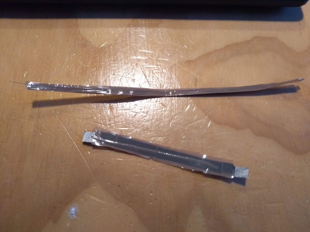
I followed the Instructables tutorial to make and test my own bending sensors. First I cut two pieces of sticky tape. They define the lenth of your bending sensor. Make them as long as you want to. Then I cut two pieces of conductive thread, 1 CM shorter then the sticky tape. I sticked the thread in the length of the sticky tape, leaving 5 mm of sticky tape on each side. Then I cut two small pieces of conductive fabric. These are for connecting to the probes of your multimeter. They should connect to the thread and stick out of the sticky tape. Then I cut to narrow straps of velostat. It should be more narrow then the sticky tape and completely cover the thread. Then I cut a third piece of velostat just like the other two and placed that over another piece of velostat allready on one of the sticky tape pieces. Then I picked up the sticky tape/thread/fabric/1 x velostat, turned it 180 degrees and layed it over the other pieces that has two pieces of velostat. Both of the sticky tape pieces should stick together so that they hold all the materials in their place. See also the pictures under here.
It works, but not fantastic. What I see is that the values of resistance are not vary stable. When bending the sensor, the value does go down, but when I stretch it again it seems to go up and then down again to around the original value. The beautiful thing is dat it actually looks like an action potential, but I am not sure if I can use this. Maybe it doesn't really mather and it's just a matter of tuning my code later on.
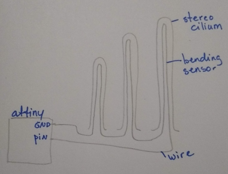
My plan is to only use one pin for all the bendings sensors in the stereocilia. I will then connect all sensors in series. For this the GND and PIN probe of the bendings sensors have to both stick out from the lower part of the stereocilia, the side attached to the cell body. This should work. And now I have to think of a way to design the stereocilia in such a way I can imbed the bending sensors in it
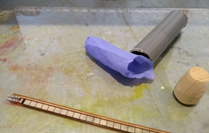
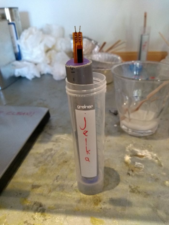
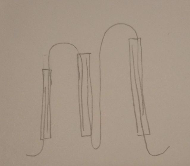
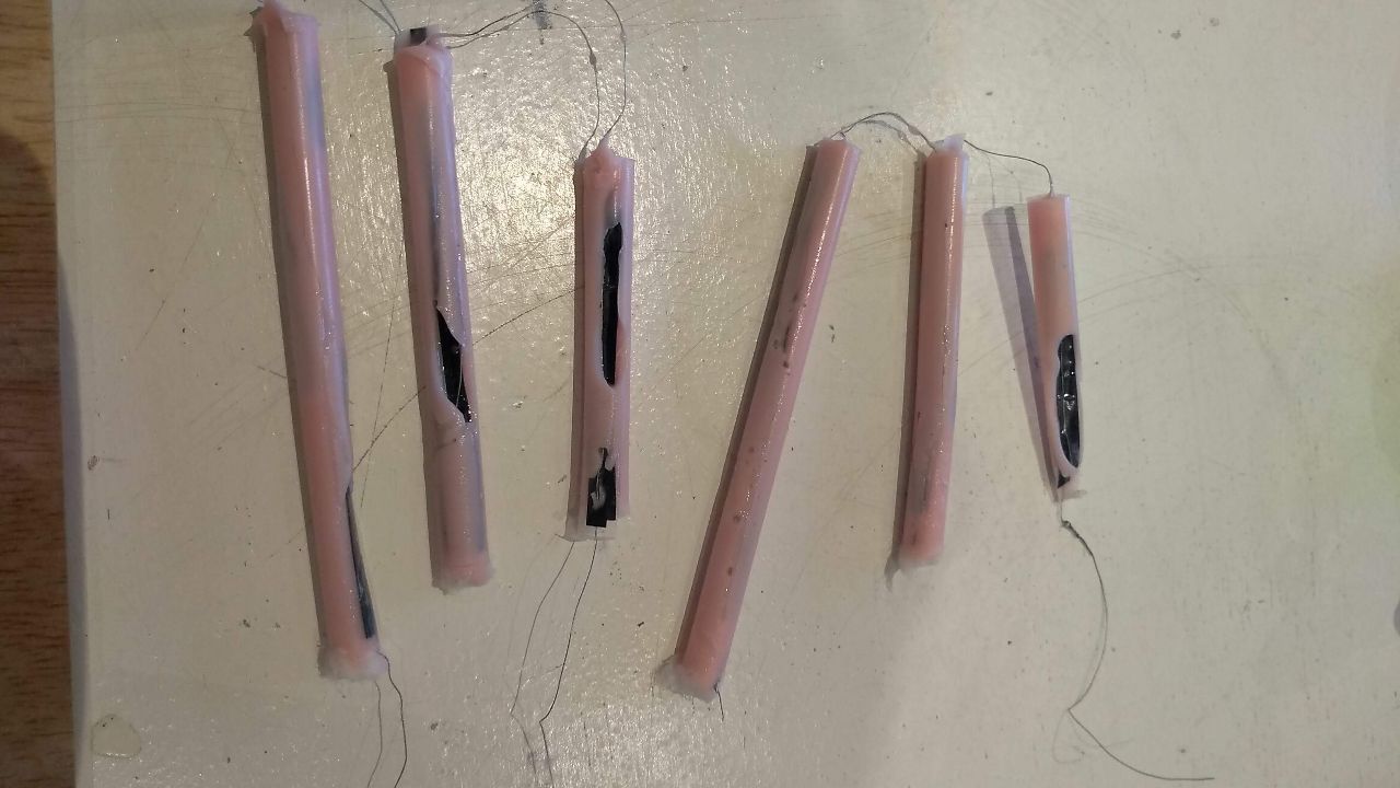
I finally made 9 bending sensors. Instead of conductive thread and fabric, that I cannot solder, I took apart an old electricity cable and used the very thin wire I found in there. This was NOT A GOOD IDEA, but I found that out much later. I connected 3 times 3 bending sensors together in such a way that the wire looked like the tip links I wanted to make. See the picture I drew. I had to cut the velostat and the sticky tape very narrow, because I decided to use Burger King straws as molds for my stereocilia. The bending sensors had to fit in there.
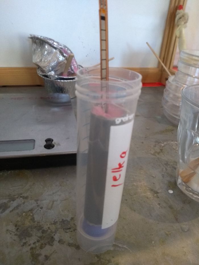
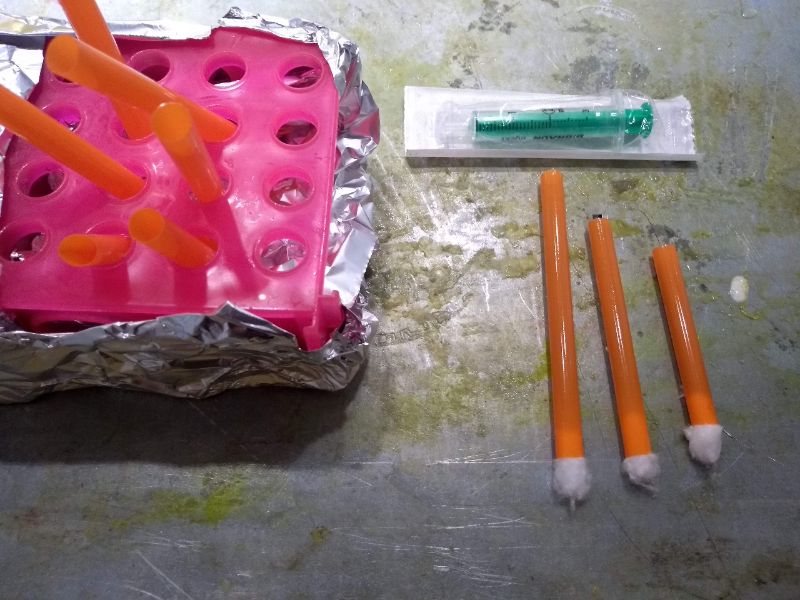
I used Mold Max 30 because I tested it earlier and it gave a good flexibilty and I liked the color. See Week 10; molding and casting for the preparation of the silicone. I plugged the straws with cotton wool and used a test tube rack to hold them. Because the straws where very narrow, I used a syringe to get the silicon in. This really wasn't easy. Off course there where many air bubbles preventing the silicone to go down. I had to be very patient waiting for the silicone to sink in and then adding a new bit.
In the second row of pictures underneath you can see the result. not very pretty. Also the wire was so fragile, it broke a few times while I was trying to calibrate them. And on top of that the values I got from the calibration where so unreliable (sometimes the resistance when way down when only touching it slightly and sometimes it responded hardly), that on monday of june 18th I decided not to use these sensors and instead of that put two pre-fab bending sensors aligned to the cilia and connect them to my bridge board.
After that I soldered the two bending sensors, or actually they are flex sensors, in series to my bridge board and calibrated them. In the video here you can see the output the bridge gives to the nodes when the sensors are bend.
Calibrating the various sensors
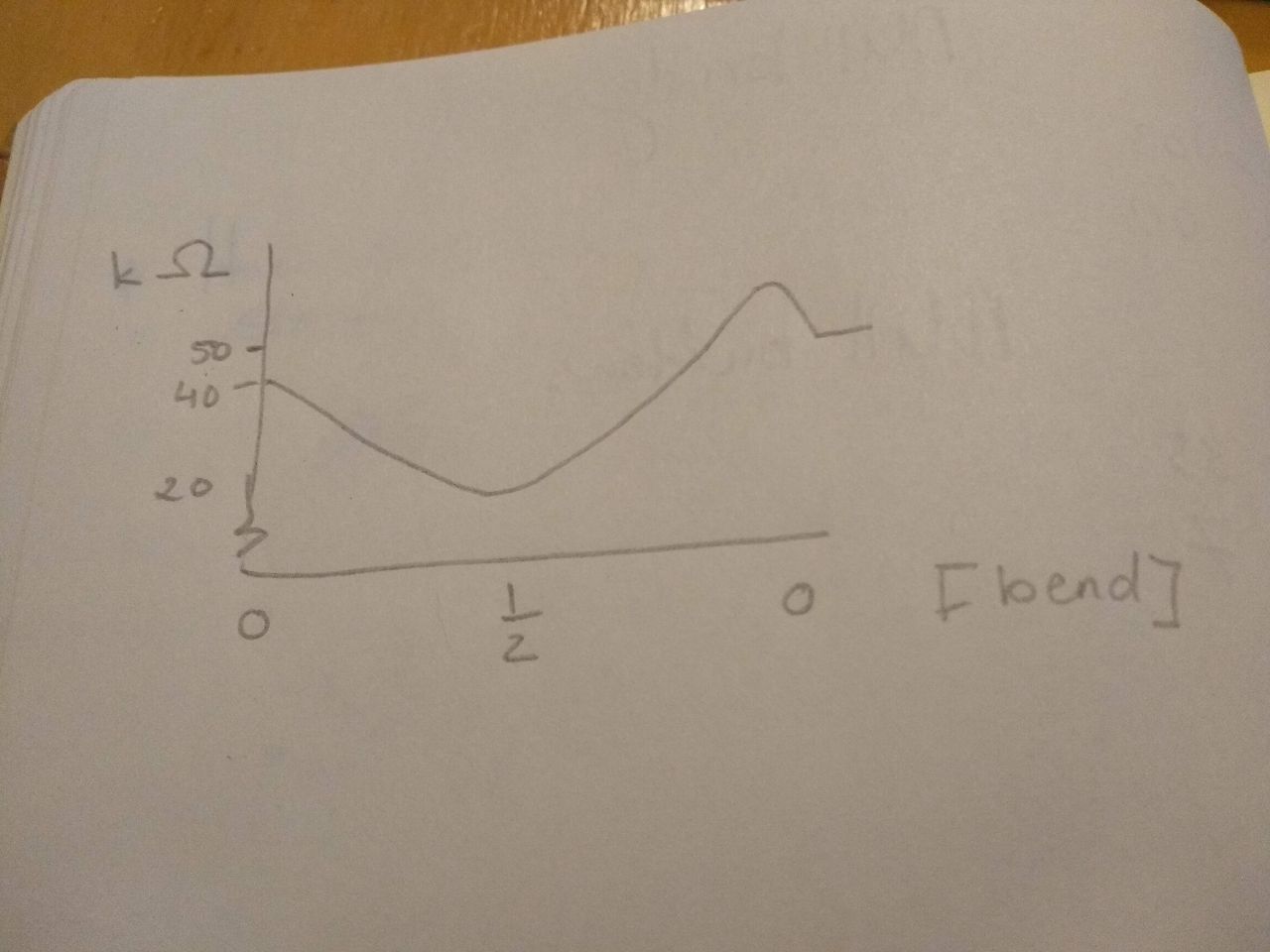
The code of the bridge needs to convert the value of the bending sensors to a message to the node boards. This means I have to include two tresholds in my code. If the value of the bending sensors is above the first treshold, the nodes have to turn of all leds, if it is below the first treshold, row 1 and 2 have to blink alternately and if the value comes under the second treshold all rows should blink alternately. So I have to set two tresholds. For this I need to know what values my bending sensor give when I bend them slightly (treshold nr. 1) and when I bend them strong (treshold nr. 2). For this I programmed my board so that it writes the input of the sensor in a serial monitor. I explain the code down here. The code itself is in the zip file on top of the page.
#include  //include the software serial library
#define rxPin A3 //define the recieving pin, it should be connected to tx of the FTDI header, so in my schematics this is the tx pin
#define txPin A2 //define the transmitting pin, it should be connected to rx of the FTDI header, so in my schematics this is the rx pin


SoftwareSerial serial(rxPin, txPin);

int pin_L_sensor = A1; //this is the pin the bending sensors are connected to

int value_L_sensor = 0;//start at 0

void setup() {

pinMode(rxPin, INPUT); //define input, unused here because the attiny not recieve data via my FTDI header
pinMode(txPin, OUTPUT); //define output
pinMode(pin_L_sensor, INPUT); //value of the sensor is input
serial.begin(9600); //set the baud rate, the speed of sending data

}

void loop(){

value_L_sensor = analogRead(pin_L_sensor); //read the stretch sensor

serial.print("the stretch sensor says: ");
serial.println(value_L_sensor); //println makes a new line for every output

delay(1000); //wait a second
}
This way I could set the first treshold to 730 and the second to 710. See also my code for the bridge board in the paragraph on coding.
Measuring resistance of various bending sensors
Many times for my final project and in the weeks before I have measured the resistance of stretch sensors and bending sensors. Both work the same; the resistance changes when you manipulate the material. The sensors do not have a cathode or anode. You can simply connect each side to either of the two probes of your multimeter. Then you turn your multimeter to measuring resistance. When I had 3 self made bending sensors in series, I had to put the multimeter on a max of 20 MOhm, but for the flex sensors alone 20k Ohm was enough.
Tip links
The tip links would be there purely for biological accuracy. They do not actually induce a signal while opening a gate, but I wanted to visually simulate it anyway. At least with a thread inbetween the hairs, but preferably with a 3D structure that resembles a tip link protein and an ion gate. If I had been able to use my self made bending sensors, then there would have been wires connecting the stereocilia that could be the tip links. But when I decided not to use them, there was no time left do design and make other tip links.
Serial network
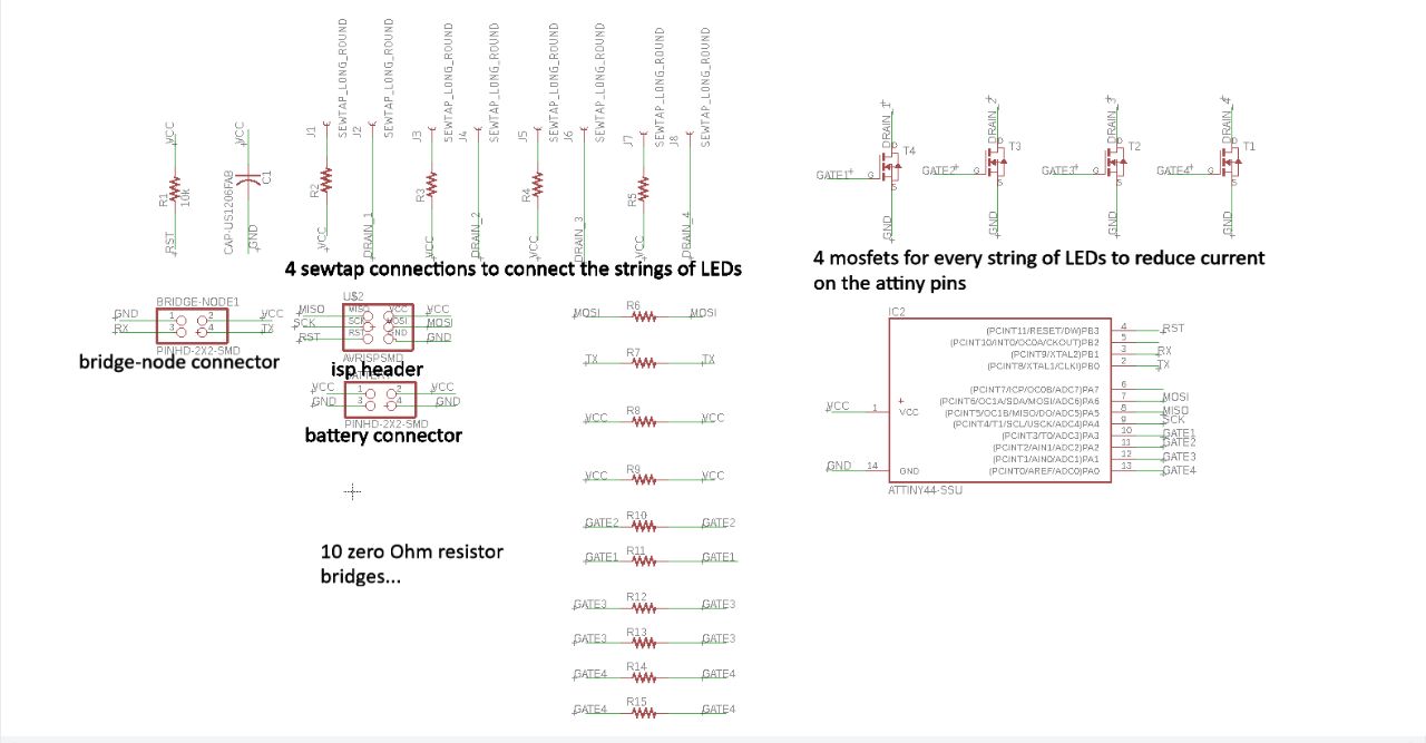
As an out put I will model three stages: low, medium and high. Low bending will make (let's say) four circular rows of LEDSs blink subsenquently. Medium bending will make row 1 -8 blink subsequently. High bending will make the signal go all the way down until row 12. I will make a serial network, with a bridge that has the bending sensors attached to it and also a 9V battery. so a regulator will be needed as well. Then I think 3 nodes that control each 4 rows of LEDs.
In Week 11: Input devices I made an input board to test stretch sensors.
I abbondoned the idea of stretch sensors in the hairs of the hair cell because I had to use a lot of force to generate a change in resistance. That kind of force would not come from the tip links in the hair cell model.
In Week 12: output devices I made a Charlieplexing board with 20 LEDS that I made blink in alternating rows . I could use it for my final project except that I would make a spaghetti of wires in my model as I want 120 LEDS blinking in 12 seperate rows.
In Week 14: networking and communication I designed a serial network with a bridge that holds a bending sensor and a node that makes LEDs blink in a string. I will improve this design to a serial network with a bridge that tranlates the change of resistance in the bending sensors to a signal to either of three nodes that each hold four strings of 10 LEDs.
June 4th
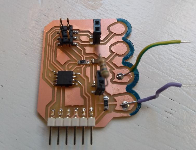
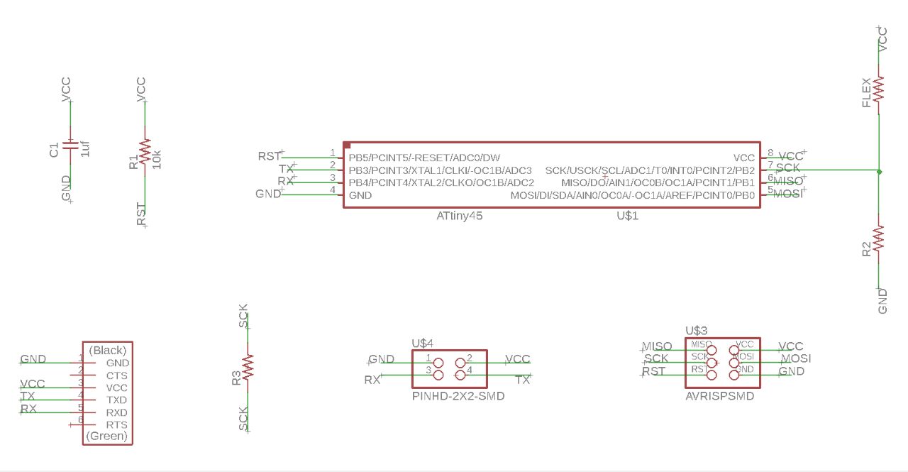
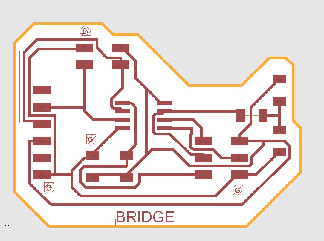
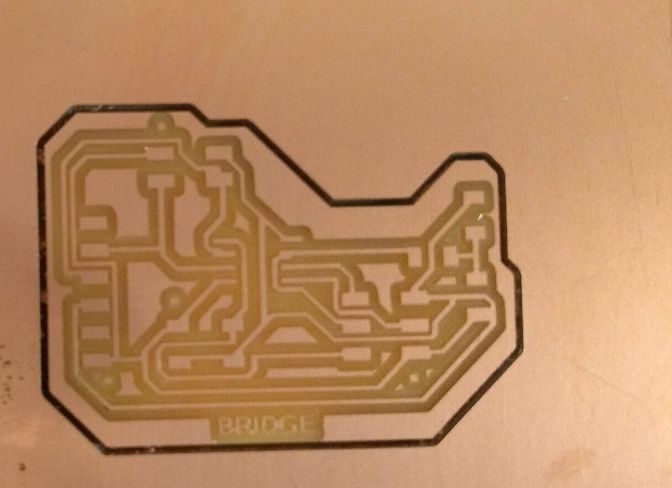
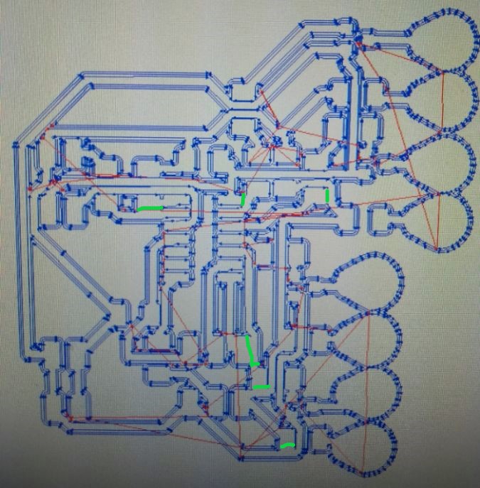
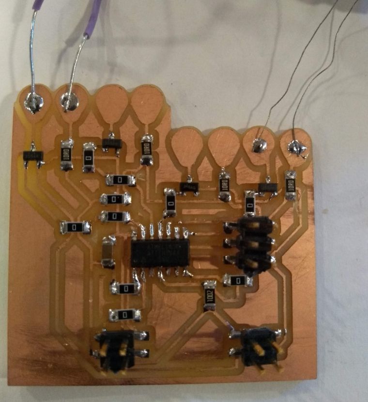
Today I milled the bridge I re-designed from the design I made in Week 14. As you can read in this week I made two mistakes on that board. So I put MISO and MOSI back on their places in the 6-pin header and connected SCK. I also enlarged the word 'bridge' as it did not come out of the engraving last time. And finally I have marked a G at the GND-pin of every pinheader. This way I don't have to look at my design files every time I connect the board to my computer or my nodes. Here's a screenshot of the design. On the top of the page it you can download the Eagle files and the PNG-files for engraving and cutting the board (and node and LED-buttons).
June 7th: Designing node 1
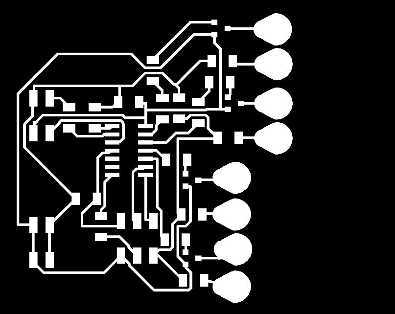
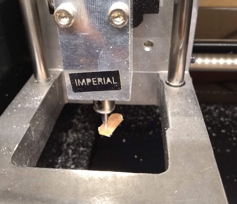
The node board is very much like the one I made in week 14. I decided not to use a 9V battery, because I don't need it for the LED strings. The forward Voltage of the LEDs is 2,2 Volts. I will put four strings of 10 LEDs in parallel, each on one pin. 5V will be enough. For a battery I will use a power bank. I will connect a USB to a 4-pin connector and plug it in a power bank. I will need a mosfet for every pin I put a string of LEDs to, like in week 14. While I was designing in Eagle I ended up with 10 0-Ohm bridges to be able to connect all components. As you can see from the pictures the traces where very close to eachother. After milling the board I had to erase 6(!) shorts that I spotted allready in the path-simulation mods made after calculating. You can find my Eagle file and PNG file for the node in the link to the zip file on top of the page.
Problems with the node 1 board
Except from the short I had to get rid of after milling the board. There where more troubles with this board. After milling the board looked really rough. The end mill I had to use (I broke mine milling the LED buttons) was kind of old. I used P600 sand paper to get rid of the rough edges. That really seemed to help. I used a brush to remove the scraps of copper. But when I started programming the board, it took me forever to find out that at two points on the board left over copper scraps made a short that prevented pin 0 and pin 1 from signalling as supposed.
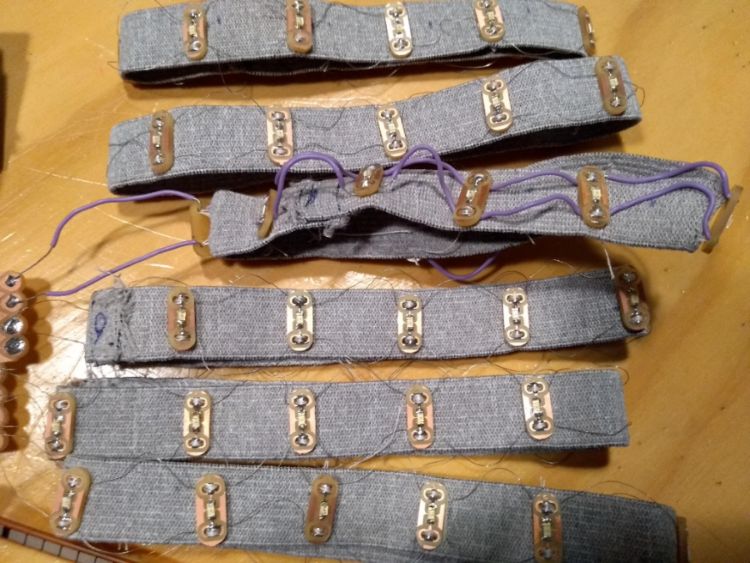
LED button strings
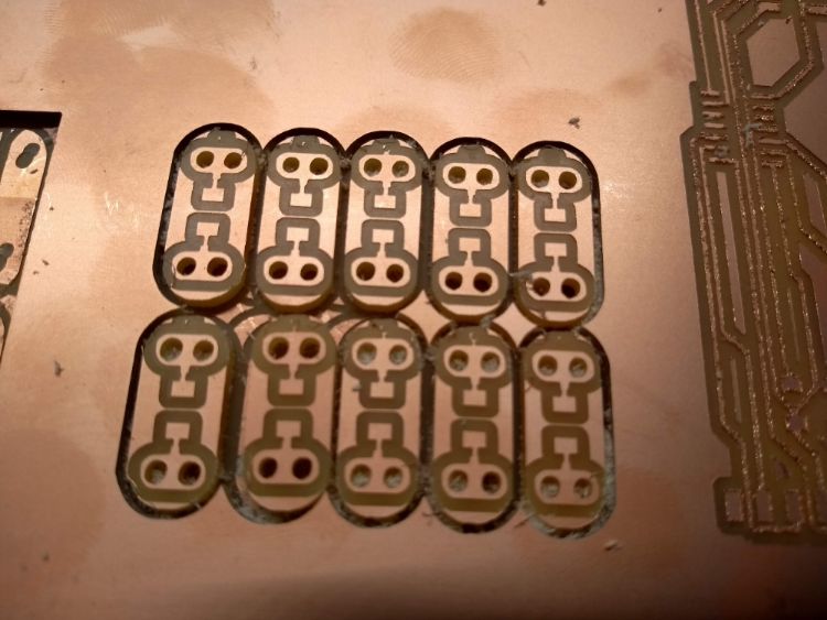
I improved my design of the LED buttons I made in week 14. As I am putting the LEDs in parallel, I have put one LED oneach button. I made a file of 10 buttons, putting them really close to eachother, but not so close that they are not cut through. When I I engraved and milled the first batch, I cut the holes in the same file as cutting the outlines. Mods doesn't aloow you to adjust the path so that te holes are cut first and then the outlines. I wrecked my end mill because one of the buttons came loose while the milling machine was cutting a hole and the outline was allready done. After that I made three files; one for engraving, one for cutting the holes, one for cutting the outline. You can find the Eagle and PNG files under the links to the zip file for bridge, node and LED buttons on top of this page.
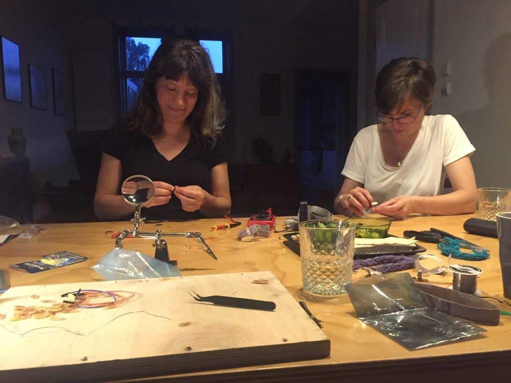
In the weekend of June 8th I had two friends over to help me soldering the LEDs on the buttons, connecting them with conductive wire and sowing them on elastic band. It took us 5 hours in total to make 5 strings of LEDs. The string with the purple wire you see underneath is a first test. The advantage of this wire is that it has isolation, but it also very unflexible. Instead I stripped an old electric cable and used the thin wires inside. Whiles testing with these strings I need to be very carefull not to make a short.
Coding the network
Underneath I will explain the code I used for setting up the network. Technically I don't think it is a network like this anymore, because I am not adressing the nodes.
Bridge code
What is does: I reads the value of the bending sensors. If the value is above 730, it tells the nodes to switch all LEDS of.If it is inbetween 710 and 730, it tells node 1 to blink row 1 and 2 alternately, with a second for each row. If it is under 710, it tell node 2 to blink row 4,5,6 and 7 to blink laternately with a second for each row. I have used the values 1-6 and a-f. Because using 7-12 gave a problem because of double digits. a is understood by node 1 to turn ON row 1, 1 is understood by node 1 to turn OFF row 1, 2 means row 2 OFF and, b means row 2 ON, and so on. All the timing (the delays) is in the code for the bridge to prevent interference of different timings in bridge and nodes.
#include
#define rxPin A3 //on my schematics this is tx, but connected to tx of the nodes

#define txPin A2 //on my schematics this is rx, but connected to rx of the nodes


SoftwareSerial serial(rxPin, txPin);
int stretch_pin = A1; //my sensor is connected to pin A1 in the Arduino pin
                     //configuration
int value_L_sensor = 0;// start at 0

void setup() {

pinMode(rxPin, INPUT);
pinMode(txPin, OUTPUT);

serial.begin(9600); //set baud rate, speed of data transmitting
}

void loop(){
value_L_sensor = analogRead(stretch_pin); //read the stretch sensor


if(value_L_sensor < 710){ //if the bending sensor is bended strong

serial.print('a');
delay(1);
serial.print(2);
delay(1);
serial.print(3);
delay(1);
serial.print(4);
delay(1);
serial.print(5);
delay(1);
serial.print(6);
delay(1000);//turn on led-row 1 for 1 second and all the others off

serial.print(1);
delay(1);
serial.print('b');
delay(1);
serial.print(3);
delay(1);
serial.print(4);
delay(1);
serial.print(5);
delay(1);
serial.print(6);
delay(1000);// //turn on led-row 2 for 1 second and all the others off

serial.print(1);
delay(1);
serial.print(2);
delay(1);
serial.print('c');
delay(1);
serial.print(4);
delay(1);
serial.print(5);
delay(1);
serial.print(6);
delay(1000); //turn on led-row 3 for 1 second and all the others off

serial.print(1);
delay(1);
serial.print(2);
delay(1);
serial.print(3);
delay(1);
serial.print('d');
delay(1);
serial.print(5);
delay(1);
serial.print(6);
delay(1000); //turn on led-row 4 for 1 second and all the others off

serial.print(1);
delay(1);
serial.print(2);
delay(1);
serial.print(3);
delay(1);
serial.print(4);
delay(1);
serial.print('e');
delay(1);
serial.print(6);
delay(1000); //turn on led-row 5 for 1 second and all the others off

serial.print(1);
delay(1);
serial.print(2);
delay(1);
serial.print(3);
delay(1);
serial.print(4);
delay(1);
serial.print(5);
delay(1);
serial.print('f');
delay(1000);//turn on led-row 6 for 1 second and all the others off

serial.print(1);
delay(1);
serial.print(2);
delay(1);
serial.print(3);
delay(1);
serial.print(4);
delay(1);
serial.print(5);
delay(1);
serial.print(6);
delay(1);// turn off all leds
}


if(value_L_sensor >= 710 && value_L_sensor < 730){ // if the bending sensor is bended low
serial.print('a');
delay(1);
serial.print(2);
delay(1);
serial.print(3);
delay(1);
serial.print(4);
delay(1);
serial.print(5);
delay(1);
serial.print(6);
delay(1000); //turn on led-row 1 for 1 second and all the others off

serial.print(1);
delay(1);
serial.print('b');
delay(1);
serial.print(3);
delay(1);
serial.print(4);
delay(1);
serial.print(5);
delay(1);
serial.print(6);
delay(1000); //turn on led-row 2 for 1 second and all the others off

serial.print(1);
delay(1);
serial.print(2);
delay(1);
serial.print(3);
delay(1);
serial.print(4);
delay(1);
serial.print(5);
delay(1);
serial.print(6);
delay(1);// turn off all leds
}

if(value_L_sensor >= 730){ // if the bending sensor is not bended
 serial.print(1);
delay(1);
serial.print(2);
delay(1);
serial.print(3);
delay(1);
serial.print(4);
delay(1);
serial.print(5);
delay(1);
serial.print(6);
delay(1);// turn off all leds
}


}
Code node 1
#include
#define rxPin 9 //this is my rx pin in my schematics
#define txPin 10 //this is my tx pin in my schematics

#define pin_led_1 0 //pin for string of buttons in row 1
#define pin_led_2 1 //pin for string of buttons in row 2
int v;


SoftwareSerial serial(rxPin, txPin);

void setup() {

pinMode(rxPin, INPUT);
pinMode(txPin, OUTPUT);


pinMode(pin_led_1, OUTPUT);
digitalWrite(pin_led_1, HIGH);
pinMode(pin_led_2, OUTPUT);
digitalWrite(pin_led_2, HIGH);


serial.begin(9600); //set baud rate, speed of data transmitting

}

void loop(){

 v = serial.read(); // make a variabel v that is read from rx pin

if(v == 'a') {

 digitalWrite(pin_led_1,HIGH);

}
 else if(v == '1'){
 digitalWrite(pin_led_1, LOW);

}
 else if(v == 'b') {
   digitalWrite(pin_led_2,HIGH);

 }
 else if(v == '2') {
   digitalWrite(pin_led_2,LOW);
}
}
Code node 2
#include
#define rxPin 9 //this is my rx pin in my schematics
#define txPin 10 //this is my tx pin in my schematics

#define pin_led_1 0 //pin for string of buttons in row 1
#define pin_led_2 1 //pin for string of buttons in row 2
#define pin_led_3 2 //pin for string of buttons in row 3
#define pin_led_4 3 //pin for string of buttons in row 4
int v;


SoftwareSerial serial(rxPin, txPin);

void setup() {

pinMode(rxPin, INPUT);
pinMode(txPin, OUTPUT);


pinMode(pin_led_1, OUTPUT);
digitalWrite(pin_led_1, HIGH);
pinMode(pin_led_2, OUTPUT);
digitalWrite(pin_led_2, HIGH);
pinMode(pin_led_3, OUTPUT);
digitalWrite(pin_led_3, HIGH);
pinMode(pin_led_4, OUTPUT);
digitalWrite(pin_led_4, HIGH);

serial.begin(9600);

}

void loop(){

 v = serial.read(); // make a variable v, that is read from the rx pin

if(v == 'c') {

 digitalWrite(pin_led_1,HIGH);

}
 else if(v == '3'){
 digitalWrite(pin_led_1, LOW);

}
 else if(v == 'd') {
   digitalWrite(pin_led_2,HIGH);

 }
 else if(v == '4') {
   digitalWrite(pin_led_2,LOW);
}
if(v == 'e') {

 digitalWrite(pin_led_3,HIGH);

}
 else if(v == '5'){
 digitalWrite(pin_led_3, LOW);

}
 else if(v == 'f') {
   digitalWrite(pin_led_4,HIGH);

 }
 else if(v == '6') {
   digitalWrite(pin_led_4,LOW);
}
}
Ion channels
I had to let go of the design wish to 3D print ion channels. There was no time.
Bill of Materials
| Materials and Components | Coming from | Costs in Euro's |
|---|---|---|
| Styrofoam 10cm | Available @ FabLab De Waag | 22,39/120x60cm and 3,11/cell body mold |
| Acrylic 3mm | Available @ FabLab De Waag | +/- 3 euro's |
| Cotton | A. Boeken textile shop | 5,95/m |
| Tarbender epoxy coating | FormX Amsterdam | 114,85/5,13 kg and 6,25/cell body |
| Bending Sensors | kiwi-electronics webshop; pre-fab sensors and DIY with Velostat, conductive thread and fabric. | two sensors 12.95/piece or/and 22 euro for velostat, conductive thread and fabric. |
| Silicone Mold Max 30 | FormX Amsterdam | +/- 3 euro's |
| Copper plate | Available @ FabLab De Waag | +/- 3 euro's |
| 60 LEDs and electr. comp. | Available @ FabLab De Waag | +/- 5 euro's |
| Conductive wire | Old cable @home | 0 euro |
| Elastic band | A. Boeken | 1,95/m |
| Buttons | A. Boeken | 2,35/20 pcs |
brief conclusion
I have learned so much in the past 6 months that my final project now seems so simple. I quess it reflects what I am able to do in 3 weeks of time. I am very happy that the cell responds sensitive and robust. And that it really looks like a hair cell. If I had to improve I would make a much nicer looking composite. I am really not happy with how a vaccuum bag works. Also I should have made seems on the cootton pieces I laser cutted for the composite. The bending sensors I should have made with a thicker, more robust wire. And I would have loved to design the tip links and ion channels as well. But. I might really make more sensory cells like this. There is seeing, feeling, smelling and proprio, but wait until you meet animal senses!
Intellectual Property
For a license I chose Attribution-ShareAlike 4.0 International. I chose this specific licence because I don't mind (or will actually be honoured) if others use my work, even for commercial use. As long if they also share their work similar like I did.