For my object, I've concluded I want it to be a wearable piece. I started off wanting just something with organic movement, and from some sketches exploring the possibilities of movement I can achieve with milled material - I stumbled onto the idea first of an organic moving sculpture, then to a wearable object.
It's going to be a kind of wearable ribcage.
To start off, I need to model this ribcage around a person, of course. So I looked or a person model for Fusion 360, to model around, and found the following model on GrabCAD:
https://grabcad.com/library/human-body-model-joints-for-fusion360-1After signing up to GrabCAD I downloaded the model. I opened the model (just double clicked the f3d file) and it opened up in Fusion:
.jpg)
Since the model came with joints already and can be posed however I want, I gave it a pose that'd make it easier for me to work with in order to model the object that I am gonna make.
.jpg)
.jpg)
First I will measure my model and find that it is approximately 1757mm, or 175cm. Since I'm 182cm, I'll make the model (of my ribcage) just a little bit larger. A scaling of:
182 / 175 = 1.04
So once I am done with the object I'm making, I will scale it by 1.04.
I'm going to start with the spine - the rear supporting structure of the ribcage. I'm going to keep it a bit at a distance because it's too thin to support my back without pain, so instead - the back of the ribs will support it, connecting to the spine.
.jpg)
Here comes something to acknowledge - as I will be using the 9mm thick plywood, so as to ensure the whole construction is not unbearably heavy, I also need to be aware that the cuts that I am making to snap fit in this model - only after being scaled up by 4% will be 9mm thick.
So if "A" represents the thickness of the snap fit holes, then:
A*1.04 = 9mm
A = 9 / 1.04 = 8.6538
Thus, these will be 8.6538mm thick. But since I want to offset the cutting by a little to ensure the fit is not too tight anyway, I will round this number up to 8.7mm. It'd be 9.048 after scaling up, which basically makes no actual difference even after the offset.
I'm not accounting for the scaling in making the dog bones, I actually feel nice about having bigger than needed dog bones, I like the holes. And I am not concerned about structural integrity - this design uses a relatively light weight and sturdy material, and I will not excessively overload it.
.jpg)
.jpg)
.jpg)
Many of the considerations I will be making are going to be based on me not wanting to make it too cumbersome, too heavy, or too limiting of movement.
I'll extrude it to make it a physical object and to continue working based on that. Its thickness will need to be 8.7mm, so a 4.35mm extrusion on both sides.
To differentiate the spine I also gave it a wood material appearance.
.jpg)
Next I'm making the visual style into wireframe, and sketching the top support ribs.
.jpg)
.jpg)
.jpg)
Then I extrude it by 8.7mm:
.jpg)
.jpg)
That's quite beautiful. Forgot about the dog bones, so I went back and added some dog bones to the rib sketch. I did the same process with the other support ribs.
.jpg)
I also added another diagonal notch at the top, I'll make a support beam there and on it I will attach some shoulder supports.
.jpg)
.jpg)
.jpg)
To the shoulder support beam there will be attached shoulder supports, to support the weight of the construction on the shoulders and through the spine and back supports.
.jpg)
.jpg)
And now I'm going to model the three lower ribs which are going to have joints and are going to wrap around the body to the front.
I'm going to connect the joints with bolts, 25mm long, 8mm diameter (M8). This means I need to make holes in them, and those holes need to be 8mm diameter after a 1.04 multiplication.
So I'm making holes with the diameter of 7.7mm.
The holes on each end are going to be a bit offset, because I have one rib connecting from the bottom and the other from the top, and want a different distribution of weight to account for that.
.jpg)
However, after some further considerations, I have decided to not repeat the offset on any of the other ribs. This is to simplify assembly under time pressure.
Here are all the ribs and the spine done. This is the entire rear half of the sculpture:
.jpg)
.jpg)
.jpg)
.jpg)
Now is the front half part! It follows the same process, so I won't repeat it. I used the other type of dog bone joint:
.jpg)
Full frontal bar:
.jpg)
And here's the finished thing:
.jpg)
.jpg)
.jpg)
.jpg)
.jpg)
.jpg)
The Sketch of all the components (re-scaled to be 1.04 of the original size):
.jpg)
Now all that's left is to cut it! And also to purchase the necessary M8 bolts to fasten the joints.
Cutting it at the lab
On the machine - I am goign to use a 5mm drill bit.
The software used to import the path and turn it into Gcode is "Partworks".
The board size is 250cm by 122cm. So I made my whole vector map no wider than 115cm and no higher than 230cm, to accommodate the screws.
I put the big polywood board (250x122) on the sacrificial plate of the machine, and screwed it to the sacrificial plate with many many screws :P.
This is to ensure it's lying flat and won't give me any trouble by moving or popping.
In the software, Partworks - I imported the DXF file (using the Import Vectors command), cleaned up the vectors and made paths out of them.
For a few of the remaining open vectors I used the Join open vectors command to make sure no open vectors remain.
The path settings are were set to "Outside" and "Climb".
In the path settings, I set the drill diameter to 4.7mm, for the purpose of having a 0.3mm offset (because my actual bit is going to be 5mm).
.jpg)
.jpg)
Save the vector path!
Then I open the software "Shopbot", which is the software that is going to make the machine do the actual cutting, and imported the vector path using "Part file load".
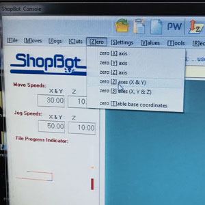
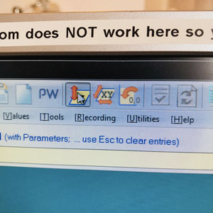
The next step is to set the X, Y and Z of the machine for the milling. X and Y are set by moving the end mill to your choice of origin. Then click the menu "Zero" and then "Axes X & Y". It very important not to click the button which looks like it sets the XY-origin.
The Z is set using the metal tool attached to the machine. Put it flat on the material:
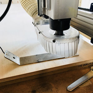
Then push the button with a Z on it in Shopbot. The end mill will descend and touch the tip of the metal plate, and will stop.
The machine was set to 14k rpm and a speed of 30 for movement and 90 for jogging, as well as 10 for Z in both jogging and not jogging.
.jpg)
.jpg)
One last thing before turning this bad boy on - for sake of safety, any long hair should be kept away from the spinning drill bit at all times, make sure you know where the emergency stop button is, equip yourself with protective gear (glasses / ear plugs).
I put the key to the side of the machine into the machine and turned it, to finally turn it on.
Run the Shotbot cutting!
The machine cut beautifully. After it's been cut, I sawed out the parts, and sanded them a little.
.jpg)
.jpg)
.jpg)
.jpg)
.jpg)
.jpg)
I decided to take it home to finish up the sanding and the assembly. After assembly, I found that the front part I made is both not usable (the bits going into it are too small, ending up actually not connecting at all, and keep falling off) and absolutely hideous and unnecessary. The rear part however is absolutely amazing:
.jpg)
.jpg)
.jpg)
.jpg)
.jpg)
.jpg)
.jpg)
.jpg)
.jpg)
.jpg)
.jpg)
.jpg)
.jpg)
.jpg)
.jpg)
.jpg)
.jpg)
.jpg)
.jpg)
.jpg)
Files:
DXF fileFusion 360 model (Rar compressed)
Back home