The process!
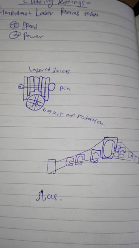
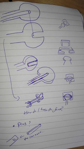
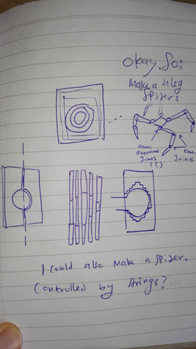
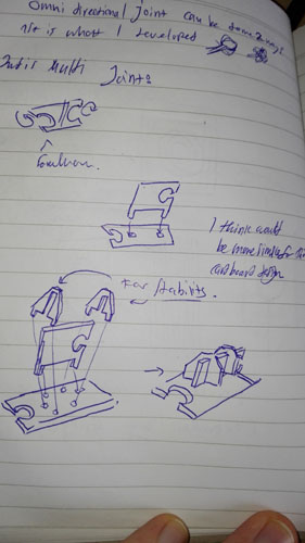
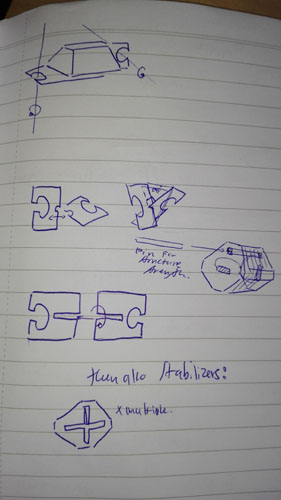
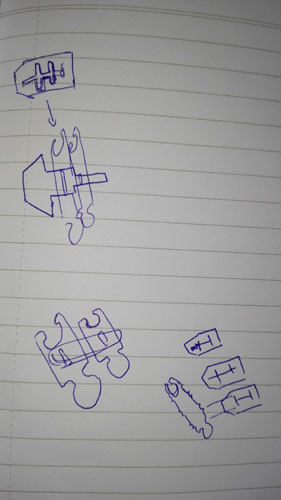
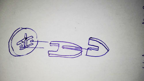
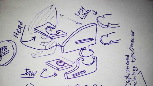
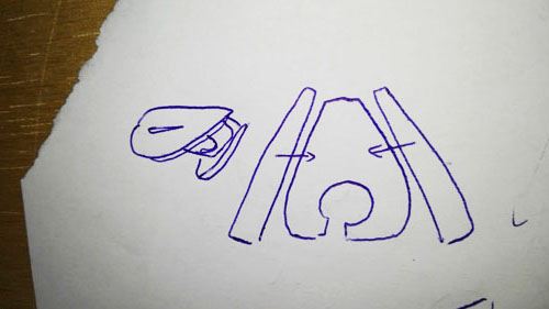
For a preliminary sketch of the joints I doodled some forms in my notebook, with emphasis being on a elaborately shaped cuts and multi-part connectivity.
Then I took to Fusion 360 again, to try and model the spinal joint of the fish and see how it would work.
First up - I sketch the literal backbone of the link.
The base of the component is a 15x30mm rectangle.
I make a bunch of little notches into it which are meant to make a tight fit with the stability block that's gonna slide on it.
Of course, an important lesson I learned from last time - keeping track of my numbers!
.jpg)
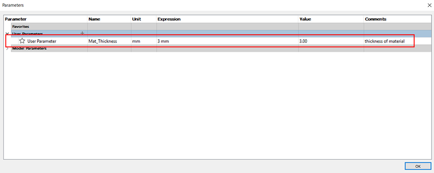
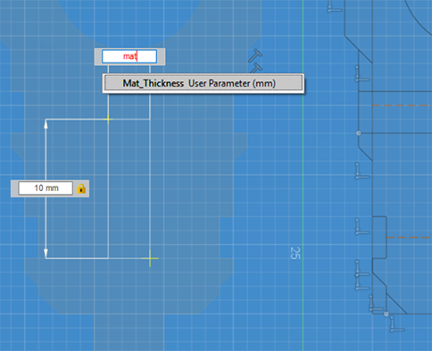
I decided to make the thickness of the material parametric. This will influence how much I'll extrude each sketch, but also the thickness of the openings used later on. To make a parameter it's Modify > Change Parameters. So I made a parameter called "Mat_Thickness" with 3mm as the value (the Expression):
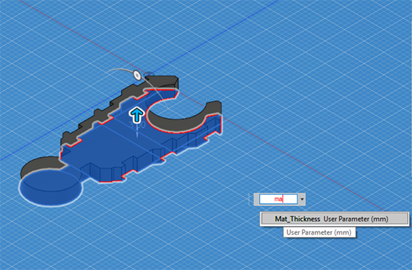
When extruding the sketch, I simply began typing in the name of my parameter and pushed the Enter key to Extrude:
After extrusion, I copied the object to test out the joint rotation:
.jpg)
.jpg)
So, clearly, the joints aren't working too beautifully. Time to re-sketch! Quick re-sketch after, the link looks pretty good, but then I put them together and there's still some problems!
.jpg)
Doing the same, after another quick re-sketch:
.jpg)
It looks FANTASTIC! :D
Now I'm gonna copy it, and make a hole in each copy, the lower link needs a smaller hole, and both are for a connection & stability pillar.
When making the rectangular holes, I put the name of my parameter in the rectangle width dimension:
All holed out!
.jpg)
The pillar!
Just imagine there is a screenshot here - I lost the picture, but the pillar's gonna show up later too!
Together with the pillar combined:
.jpg)
.jpg)
Along the way I find that having multiple sketches, on multiple planes, looks devastatingly cool.
.jpg)
It's like building a spacecraft in space.
Next - I sketch the stability sheath.
Quick note - the stability sheath uses the Mat_Thickness parameter as the thickness of those criss-crossy shapes in it.
.jpg)
Put together:
.jpg)
.jpg)
.jpg)
This should make for a very solid, sturdy and flexible spine structure for the fish.
Actually I think maybe I'll make it to a Dragon, rather than a fish. A chinese Dragon.
It is decided! (for now)
Now knowing how the links will work and will assemble, it's time to export some DXF files of my sketches from Fusion 360 into my Illustrator trial.
I just right click on the sketch in the lefthand objects menu and click to Save as DXF. Then I just open the sketches in Illustrator.
After that, I adjust the scales of everything a little to fit into my grid and make work easier. I won't bore you with the math, it's simple, and here's the adjusted sketches in Illustrator:
.jpg)
The dimensions are not 100% set yet, because I still want to adjust the offset after running the Kerf test, but for the time being this is just right :)
Now that I have the spinal link assembly structure, I probably need some sort of body. But to be honest, I don't see it being a dragon very much. Nor a fish. Maybe a snake? That was kind of my first idea, and should be simple enough. So let's make it a snake!
How do I snake it then?
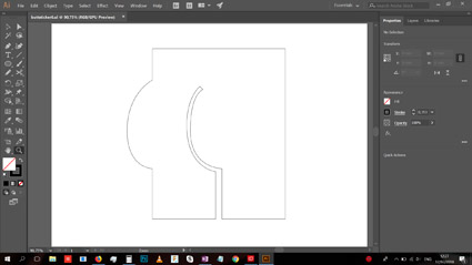
I think the way to snake the spine is to take the stability sheath:
.jpg)
And to turn it into a circle. So, it'll still slide onto the link, and will do pretty much the same, but it's shape now will have an actual reason. I'll make it kind of circular, with a slightly flat bottom, to imitate a snek.
The current structure's width is 25mm (2.5cm), so I'll make the cirlce have a tiny bit wider diameter, like 30mm or 35mm.
After a bit of testing I decided on 35mm.
About 60 to 65% of the way down, I'm also making the circle flatter. I'm basically just eyeing this to look good, and it's not really an important parametric scale.
Like this:
.jpg)
.jpg)
So that's gread. But a true snek has two additional components - a head and a tail.
To make the tail, I suppose I could copy the regular links, shrink them, and adjust them to connect to the next bigger link, but I don't feel like doing it. Instead I'll keep the same inner links, but will do the following:
Make two more slightly more shrunk versions of the snek body circle, and make one final spinal link which connects like all the others but has no rear connector and instead ends in a spiky pointy end.
So I'm first gonna copy the snek shapes twice, making them 0.75 and 0.5 in scale of the original.
But after doing a 0.75 scale, turns out it won't get much smaller than this with the current link structure size:
.jpg)
So I'll just stick with 0.75. I also changed my mind about the final pointy spiky tail link. I wanna do something else. What I wanna do, is something like this:
So the design:
.jpg)
.jpg)
.jpg)
Now all that's left is the head. Something like this should suffice:
Just a simple shape, connecting with the last link of the snek body, and with a movable Jaw. Or maybe even a more simplified version, if I want it to have a pointier shape, more akin to an actual snek's head.
Which, now that I think of it, is exactly what I want to do.
So something like this:
.jpg)
And measuring the head's triangle, with a little bit of pythagorean theorem, I have the right length of the head sides:
.jpg)
And I also measure the distance between the two main link points in the stability pillar:
.jpg)
.jpg)
This will mark the max distance between the two farthest points (the top link's top surface and bottom link's bottom surface) from one another, to know how to better measure the head sides.
Now, I know the angle of the head triangle's slope is approximately 295.71 degrees, so to make the snap connectors from it to the sides of the head I'll need to make them at 90 degrees to the 295.71 degree slope. So, 385.71 degrees (295.71 + 90), or 25.71 degrees.
.jpg)
Looks good. So then just to make a connector with the right length and width (5mm x 3mm), copy it at a 7mm distance, and then rotate them both by 25.71 degrees:
.jpg)
Looks good!
I mirrored it and put it on the other side, and this is the complete snek head triangle.
.jpg)
Now the side of the face with the measurements I've taken:
.jpg)
.jpg)
.jpg)
.jpg)
.jpg)
And now just to make copies of every object a couple of times to have exactly the necessary amount of links & everything.
Each of my links, back to back (when connected) is 320pt, or 32mm or 3.2cm.
So, let's say I want a 32cm long snake body, not including the head, or the tip of the tail (but yes including the thinner end of the tail, of which I'd like to have two).
So it's 8x times copy of the big snek belly objects, 2x times copy of the small snek belly objects, 10x copy of the links & stability pillar, and 1x copy of everything else.
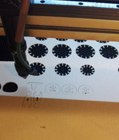
Here's the full sheet to feed to the laser cutter:
.jpg)
.jpg)
Following the team assignment's test, the cardboard Kerft turned out to be 0.22909091mm.
I don't know if a different material would have a different Kerf, I guess I'll find out in class, but for now - I need to offset my design by the appropriate amount of kerf.
Since all my measurements in Illustrator are in points, first I'll convert them to Millimeters. I transform the unit time to mm instead of points (Edit > Preferences > Units). Then I select a component I know is corresponding with 3mm in width - the small rectangle slot in my link:
.jpg)
It's 10.583mm account for the new units. To make it 3mm, and in fact to make the entire model the right scale, a little math is in order:
X * 10.583mm = 3mm
X = 3mm/10.583mm
X =~ 0.283473495
So the entire model needs to have it's scale multiplied by this amount.
I selected it all, it's width total is listed at 1026.434mm:
.jpg)
And 1026.434 * 0.283473495 = 290.966833367
Of this I'll take just 290.966.
Now - to account for the kerf.
This unfortunately means that I need to get rid of most of my copied instances of each object, because I'm just gonna be adjusting it in one, and then copying it again.
I don't need to adjust everything to accommodate the Kert, just the bits which are going to be connecting and snapping.
First, to make it easier, I'm just going to scale the whole thing to compensate for the kerf with all the inner connector slots.
Once again, it's simple math.
I take the width of the same connector slot, which is now 3mm, and do the following: 3 - 2*0.22909091 = 2.54181818
This'd have to be the width of the 3mm connetor slot accounting for the kerft.
So to scale the whole thing:
X * 3mm = 2.54181818mm
X = 2.54181818mm / 3mm
X = 0.84727273
So the model's being scaled to this multiplication.
Once again I select the whole thing - it's 155.059mm wide:
.jpg)
And 155.059 * 0.84727273 = 131.37726224 Of which I'll take 131.337 and that's the number I'll put in the width measurement.
.jpg)
Quick check on the measuring stick I'm using:
.jpg)
Yep, measurement's correct, it's at 2.541mm now.
Now I'll adjust a few extra items in the stability pillar and some others, just to make sure all fits are tight. Only the bits which are fitting into / onto another one.
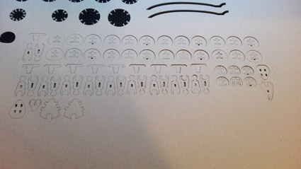
After doing this - again I made all the copies of all the things, and we now look like this:
.jpg)
Saved it as Illustrator CS2, "Uncompressed", because that is what the laser cutter needs.
It was time to print! I copied by Adobe Illustrator CS2 uncompressed file from my USB stick to the computer in the lab running the laser cutter.
I opened up the software LaserCut5.3 and imported the print file (File > Import).
I then selected most of the components and deleted them, because I just wanna do a quick test run with a few parts only before committing.
The path setting was set to "Cut", and I used "Power: 80" and "Speed: 70".
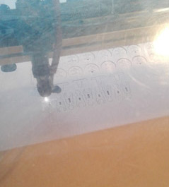
After setting everything to the correct setting, I turned on the laser cutter.
I put in the cardboard sheet, positioned the laser where I wanted it, checked it's height from the cardboard, closed the laser cutter and went ahead and turned on the laser too.
Then in LaserCut I downloaded the paths to the machine, pushed the "Test" button on the laser cutter to check where it'll cut, and hit the "Start" button, to start the laser cutting.
Super important note - at the end of it all, I cleaned up the machine!
The test bits I printed out for measurement, with one point corresponding to one mm:
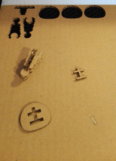
Most bits fit together relatively well, but it's too tight for cardboard.
As I was putting it together, the tight fit actually started breaking an important part of the link:
Thus I rescaled it again. Checking the current scale of the whole selected set of objects, in the laser machine, it's 439 in width.
I first did a re-scale to 485, but got the same bad results. I then tried 495, and results were better, but still too tight.
I eventually re-scaled it to 505, a 1.15 multiplication (15% increase).
After the final re-scaling, I sent the full set to cut.
Last but not least for now - the Vynil sticker! For the sticker, I'll just design a butt, with the pen tool.
It's a butt.
Nobody here knows me yet, but, yeah, it's a butt. For valentine's day.
I cut the butt on the cutting machine, using Red vinyl, and 90g of pressue. In fact, I cut a series of them!
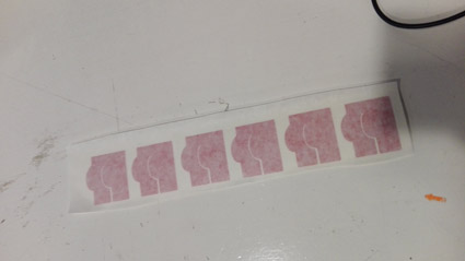
I got this beautiful strip by cutting the piece of vynil with the butts, removed the excess, put on top of it a special film that sticks to the top of the vynil, and voila!
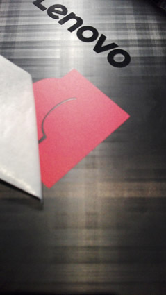
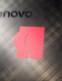
Only my most beloved people received on, including my computer.
To apply simply take off the bottom tape (like with any other sticker) and apply the exposed sticky side of the butt to my computer's surface.
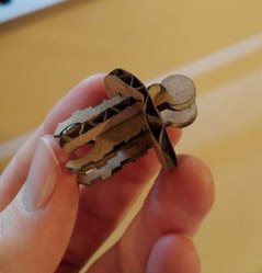
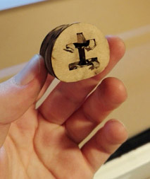
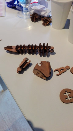
Back at home, during the assembly of snek, most of it went smooth, but there was one particular issue whereas specifically the extruding snap bits:
.jpg)
Turned out to be actually too long. 0.5mm is, as it turns out, too much for it to snap effortlessly as I was intending, so I ended up cutting those pieces a little to make them a tiny bit shorter, and more easy for the cardboard to get dressed on.
I relied on the cardboard's flexibility to slide over those extrusions, but as it turned out - cardboard is less flexible and more briddle & fragile, making it a very tough material to work with at this small scale.
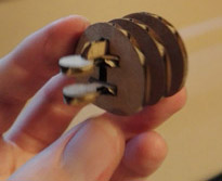
I assembled the snek, with only two pieces broken.
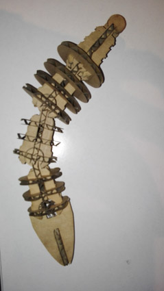
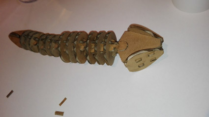
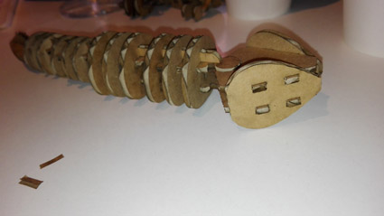
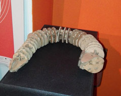
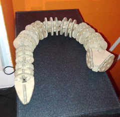
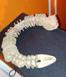
The sneak's head didn't keep on. I forgot to design anything which holds it in place once the joints are linked, and as a result it's unstable. But looks perfect when still!
An important lesson I learned is a lesson in material. I counted on the cardboard's flexibility, but on a small scale, it's the opposite of flexible, it's hard, and fragile, and easily mishandles.
The design files for this one:
Butt sticker Illustrator file
Dragon/Snake Illustrator file
Dragon/Snake DXF file
Dragon/Snake f3d file to open the model in Fusion 360
Back home