Getting back home, I decided to run a little brief experiment with the modular ATTINY84a microcontroller, and just try to run the motor in both directions without any special circuitry. So I'm going to just connect the wires of the motor to some of the pins on the board. The pins I have available are:
PA2 -
Analog-to-digital converter input
Pin change interrupt
Analog output, negative input
PA3 -
Analog-to-digital converter input
Timer/Counter
Pin change interrupt
PA7 -
Analog-to-digital converter input
Timer/Counter
Input capture pin
Pin change interrupt
PB2 -
External Interrupt 0 Input
Timer/Counter
System Clock Output
Pin Change Interrupt
And I think I can use all pins as outputs?
I'm not sure, so I'll pick PA3 and check.
This seems to work, but only when the negative motor pin is on it.
It doesn't work the other direction.
Okay now I'll try to have one output HIGH and one LOW and connect those two together.
This works.
Now I'll try to make them alternate every X cycles on the chip, and see if this changes the motor's direction.
An arbitrary value, I chose 200. Nothing's happening. Perhaps the cycles are too short, the clock is actually very fast.
Every 20000 cycles :P
Well it works now, but it doesn't actually change direction without me switching the wires after each cycle.
Good to know!
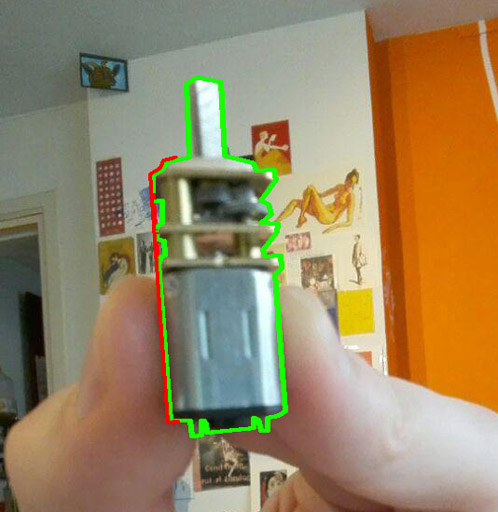
I got a new motor, one more fitting for my purposes. The motor I got is awesome, it does 30 RPM (1 full turn per 2 seconds), with a little system of gears that step down it's speed:
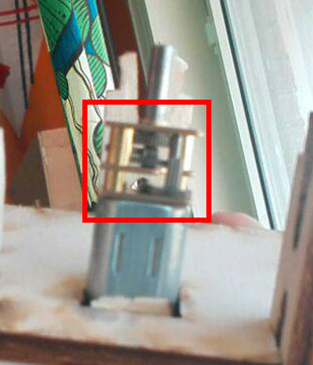
This means that all that fast, but weak spinning is being translated into slow, but strong spinning - with more force. Energy preservation rules ahoy!
The most important thing about it is that I can change it's rotation direction without a motor driver! Just change the LOW / HIGH outputs between the pins.
It's spinning rod is a circle with a 3mm diameter, and it's cut off point is about 2.2mm. I tested it with a 5 volt flow, it's really strong and not easily stopped.
As I recall, from measuring the plywood plates in class - it's 3.03mm. So I can just approximately say it's 3mm, since the rest will be taken off as the kerf anyway.
It's 3mm for the diameter of the motor wheel, and 2.2mm for the section that's cut off.
I'm going to make three gear wheels, and the rest of the equipment listed above.
As always in Fusion 360 it's sketch the shape, extrude it to check it out, etc etc.
The first gear wheel is gonna be 3cm diameter, and the other two will be… 3cm too. Why not. This way I won't need to worry about the gears fitting.
.jpg)
.jpg)
Now to add the gears - I'll add one gear and then just make it have a circular pattern, and combine the bodies into one.
.jpg)
.jpg)
Now I'll copy the wheel, and make a small change - the center will have a rectangular opening, for a flat clip to go through, as I'll use my own axes when operating the actual mechanism. And while I'm at it, I will also make another thing - the gear axis, 1.5cm in diameter, with the wider parts being 2cm in diameter.
.jpg)
.jpg)
.jpg)
.jpg)
Moving some things around to make them in the configuration I will use them in, and copy the copy gear wheel:
.jpg)
Now make a square to stick the wheels in. Oh - and I'll need a little thingie, a little clamp, that would hold the wheels together.
.jpg)
.jpg)
.jpg)
.jpg)
Actually I'll need a longer pin, for the spool!
.jpg)
.jpg)
.jpg)
And I'm gonna go ahead and mark some spots on the plate that are gonna have nails through them. Those spots are going to be engraved. In fact - a few other markers will be engraved, to be used as the markers of the positions!
.jpg)
.jpg)
Not to forget the last hole - small circular hole for the motor stick, and the holes for the spool gear axes.
.jpg)
.jpg)
.jpg)
.jpg)
Okay so that's great. Now I also need to hold the motor itself. The motor will be upright. Or you know what - the whole thing will actually stand up sideways. Anyway the motor needs a little compartment all for itself. The length of the part of the motor that I'll use, including a little plastic part I'll be adding:
The length then is 2.4cm on the motor (part I use) itself, and the plastic component is 1.2mm. So 2.52cm, 25.2mm. The motor is not round - it's kind of, oval. Or rather, more rectangular. It's base rectangle width is 1.2cm, and the height is 1cm. I'll shave off 1mm on each side, so I'll make a slightly smaller hole to fit only the motor's rear butt plugs. I'm making another plate, and it's distance from the main plate will be 25.2mm and it will have a little rectangular hole in it, where the motor's rear will be, 10mm wide and 8mm tall. And of course the motor itself will need to be held, which I'll do with an extra plate, specifically to hold the base of the motor, which will be held by the pins that are going to be holding the entire thing together anyway.
.jpg)
.jpg)
.jpg)
.jpg)
.jpg)
.jpg)
.jpg)
.jpg)
.jpg)
.jpg)
.jpg)
Now to turn this into a vector file - I'm basically just going to delete all my sketches, and all the bodies not used. Then I'll right click on each body face, and select "Create Sketch". This will open a new sketch on the same plane. Then I use Project, project the model to the plane, then select all > right click > break to break the connection of the projection, and now the shape is just a regular sketch and I can move it or copy it.
.jpg)
I have a big square around it all, 220mm x 220mm, to ensure that when I import it into the laser cutter program that I will be able to scale it correctly, knowing that the surrounding square has to be 220mm by 220mm.
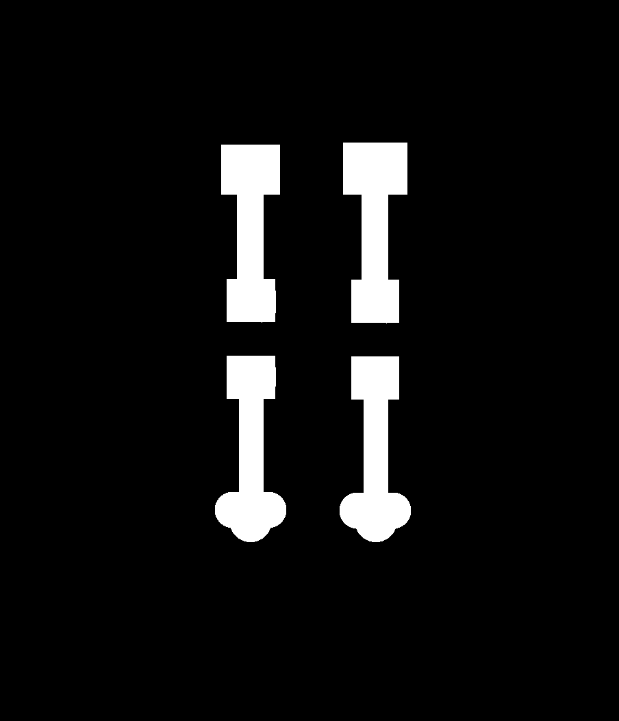
I cut the gear box parts out of 3mm plywood:
.jpg)
.jpg)
.jpg)
And put it all together to test it out at home. It's good! Took it apart again to glue the necessary bits and bobbles, like the string to the spool, or some lollipop sticks to the endmost engraved markings on the big plate over which the strings will be carried over.
Since I also have to design a board for this one too, I designed a quick little board just to transfer the current from the microcontroller to the motor. And since It's going to be basically a pointless board that does nothing on it's own, I figured I'll give the ole 0 ohm resistors a try to see how they work, since I haven't ever actually used them.
Here's the board:

.jpg)
.jpg)
.jpg)
Here's the whole thing put together:
.jpg)
.jpg)
.jpg)
.jpg)
.jpg)
More clearly:
And final tidbit - the code!
The goal here is simple - the code just runs the necessary amount of steps from the position it is on to the position it needs to be, and selects the position each time at random.
Plug it into the Serial port - and it works! Sort of.
The motor spins in both directions, but the step size is not correct (how many code cycles to run a particular movement to make it accurate), and some of the wire connections keep being iffy and stopping my motor until I place my finger on them and reconnect them, and lastly - the code is too heavy! All that serial printing for debugging purposes is making it run unreliably (even the Arduino IDE says "Low memory available. Stability problems may occur.", and they do - but the important thing is that it works! For the most part.
Wonderful!
Unfortunately, Emma told me that I cannot just connect the motor straight to the board, and have to use a transistor, and to connect the motor to the power supply directly.
So I designed a new board with a Mosfet:
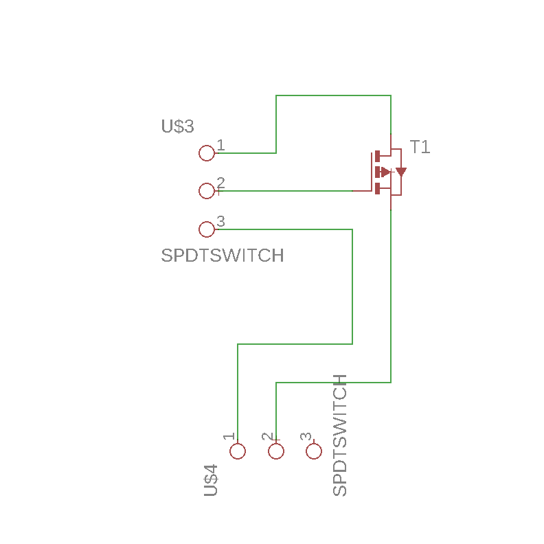
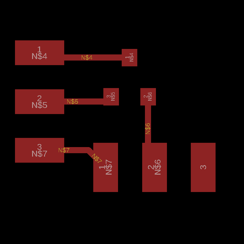
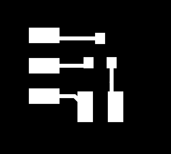
And the actual milling map:

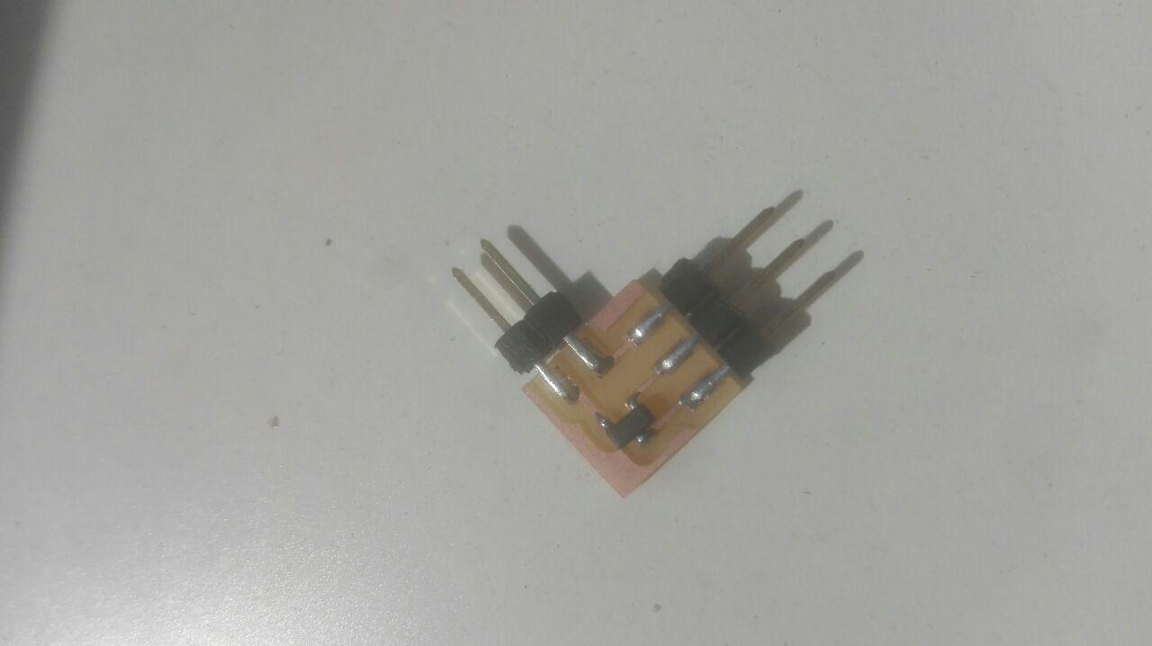
Aaand the actual cute mosfet:
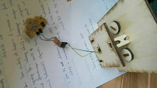
Then I connected it all together:
The motor to the mosfet and to the power supply.
The mosfet to the board, via the Gate pin of the mosfet and the PA2 pin of the board.
So it looks like this:
.jpg)
.jpg)
.jpg)
.jpg)
.jpg)
And I just run a quick code from my modified hello board that intermittently turns digital write from PA2 on and off:
This code will just run the motor forward for 500 cycles, and stop for 500, then repeat.
Okay so it's not perfect, the connections are kinda bad (you can see me manually needing to pin the wires to the battery), but considering this mosfet board was a last minute addition, and basically just there to make the motor run as an output device for the board, I'd say it's good enough for now :D
Files for the Eagle board and schematics:
SchematicBoard
Back home