Week 15: Machine building
Download the code
Assignment requirements
The first checklist
Design a machine (mechanism + actuation + automation), including the end effector, build the passive parts and operate it manually.
The second checklist: Learning outcomes
- Work and communicate effectively in a team and independently
- Design, plan and build a system
- Analyse and solve technical problems
- Recognise opportunities for improvements in the design
The third checklist: Has your group
- Shown how your team planned and executed the project
- Described problems and how the team solved them
- Listed future development opportunities for this project
- Included your design files, 1 min video (1920x1080 HTML5 MP4) + slide (1920x1080 PNG)
Doin' it
We divided the tasks. I would provide the basic motor code, Xavier would solve problems between the motors and the machine (making sure it behaved the way it was supposed to) and Dima would do final finessing of the code and automation.
I did some work trying to prepare for this week, assuming that I would be making a board to control the motors. When Emma did the local session on Friday I discovered that we were going to be provided an Arduino and a motor shield, so all of this work was kind of wasted. (Well, not wasted, just not immediately applicable and time that I could have spent on my final project.)
I tried getting my boards from output week working. I thought this would be a good step to preparing for controlling the karaoke machine. Wouldn't work. What happened? The wiring actually looks very weird on the boards. The schematic has some connections that shouldn't be there, and the PCB doesn't match the schematic, even though Eagle gives me no complaints.
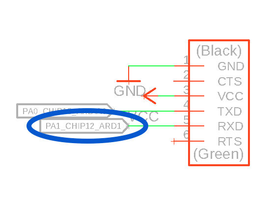
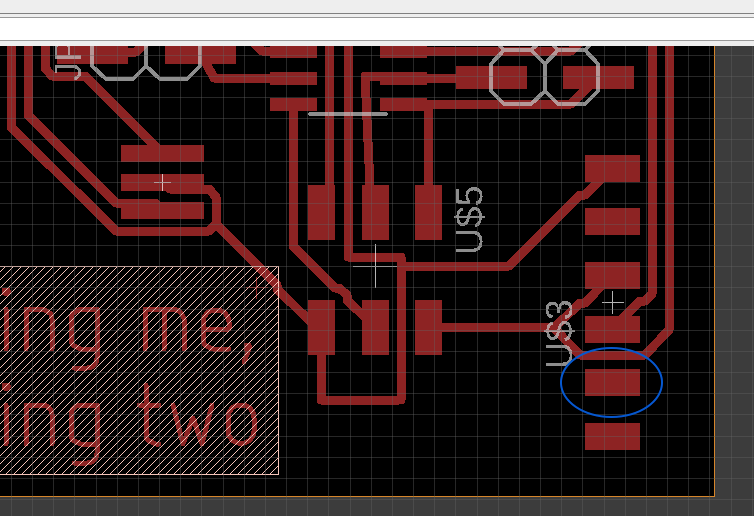
Upon further inspection, I made a typo in my net names. I misnamed the RX line. Because I didn't use serial that week, it never appeared as an issue. Notice the problems here, typo, and then missing RX trace:
Because I was away from the lab, I couldn't make a new board, so I abandoned the boards I made and used an Arduino and a breadboard, with the DRV8825 plugged into the breadboard. The wiring was the same as Output week, specified here, with the "microcontroller" of the STEP and DIR pins of the motor driver connected to two pins of the Arduino.
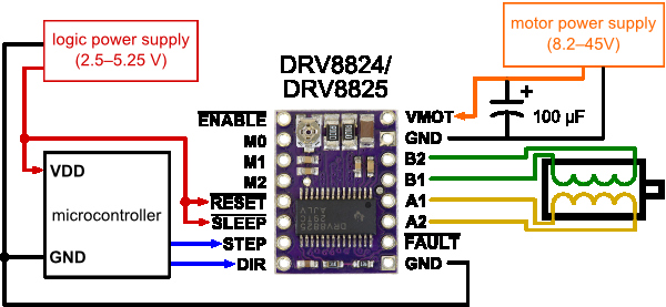
The current limit of the motor driver was already set from Output week, and I used a 12V power source again.
The original code used full steps, not microsteps. I was commited to getting that code working smoothly, first. And, ultimately, the machine design didn't use gears, so I assumed that motor would need to move large angular distances, so full steps were best. The raw code that I was using, from Emma, wasn't working. The motor was kind of pulsing, but not turning much. Because I was using an Arduino, I thought I might as well dive in to try the stepper library. The stepper library works. Imagine that. I tried playing with the RPM setting, but setting it to numbers higher than the original 120 seemed to break the code. So stick with 120.
Also, the .rotate(degrees) notation didn't seem to work. But the stepper.move(steps) did work. I don't think it will matter for us whether we tell it to move steps or degrees, since we'll be calibrating by hand and correlating the numbers to how much the roller or belt will move. I would include a copy of the code here (based on the stepperdriver library examples) but it is copyrighted under the MIT licence and I don't have the time to figure out what obligations I have if I want to share the code. Good job.
… a little later…
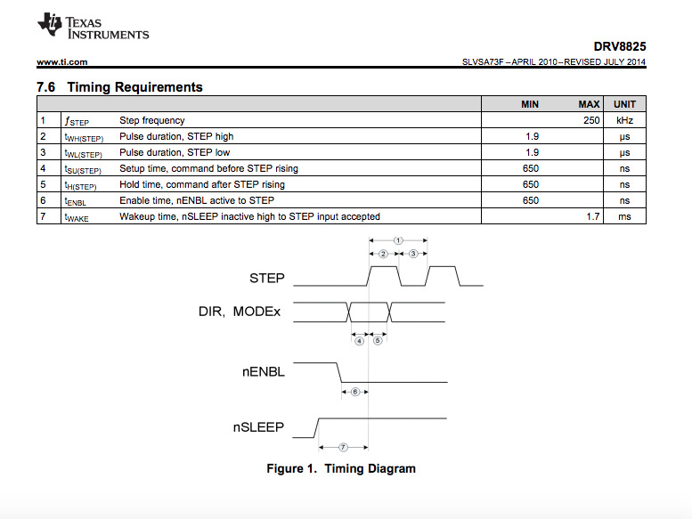
I just got Emma's original code to work. I moved the timing between the pulses from 30us to 500us. Testing the limit of this let me go down as low as 450us. Emma suggested that the short timing works for microstepping, but because there is a greater distance to travel for full steps, that short timing doesn't work. This doesn't quite correspond to the information on the datasheet, which says that the timing pulse should be 250 MHz, and the pulse high and low times only need to be 1.9us. I'm not quite sure there's anything I can do about this. See here:
I started to redesign a new board, and then found out that Emma was supplying us with an Arduino and a motor shield with motor drivers, the same as I had used in the previous week. Now that the code works, I can adapt it for the motor shield. I changed the pin numbers to correspond, according to the shield's specifications. The code looks like this at the moment:
/* Fab Academy Karaoke machine
 *  David McCallum, Xavier Klein, Dima Paley, 2018
 *  sintheta.org
 *  Code adapted from http://aconcaguasci.blogspot.nl/2016/11/arduino-cnc-shield-control-stepper.html
 */


// Motor stuff
const int ENABLE = 8 ;

const int  motorX_DIR   =  5;  //Direction pin
const int  motorX_STP    = 2;  //Step pin

const int  motorY_DIR   =  6;  //Direction pin
const int  motorY_STP    = 3;  //Step pin


//Input
const int endstopPinX = 9;
const int endstopPinY = 10;


//Driver Timing
int delayTime=30; //Delay between each pause (uS)


void setup(){

  serial.begin(9600);

  pinMode(motorX_DIR, OUTPUT); pinMode(motorX_STP, OUTPUT);
  pinMode(motorY_DIR, OUTPUT); pinMode(motorY_STP, OUTPUT);

  pinMode(ENABLE, OUTPUT);
  digitalWrite(ENABLE, LOW);

  pinMode(endstopPinY, INPUT_PULLUP);

  zeroMotor();    // zero the motor to the edge

}

void loop(){
  motorTest();
}


// move the motor until the endstop is reached
void zeroMotor() {
  int zeroingStep = 1;    // how many steps to take while looking for the 0
  int zeroingDelay=1;    // number of ms between steps

  while (digitalRead(endstopPinY) == HIGH) {            // if the button isn't pressed, move the motor 1 step
    step(false, motorX_DIR, motorX_STP, zeroingStep);
    delay(zeroingDelay);
  }
}


// Spin each half a turn, twice, and then backwards
void motorTest() {

  step(false, motorX_DIR, motorX_STP, 100); //X, Clockwise
  delay(1000);
  step(false, motorY_DIR, motorY_STP, 100); //X, Clockwise
  delay(1000);
  step(false, motorX_DIR, motorX_STP, 100); //X, Clockwise
  delay(1000);
  step(false, motorY_DIR, motorY_STP, 100); //X, Clockwise
  delay(1000);


  step(true, motorX_DIR, motorX_STP, 100); //X, Clockwise
  delay(1000);
  step(true, motorY_DIR, motorY_STP, 100); //X, Clockwise
  delay(1000);
  step(true, motorY_DIR, motorY_STP, 100); //X, Clockwise
  delay(1000);
  step(true, motorX_DIR, motorX_STP, 100); //X, Clockwise
  delay(1000);

}
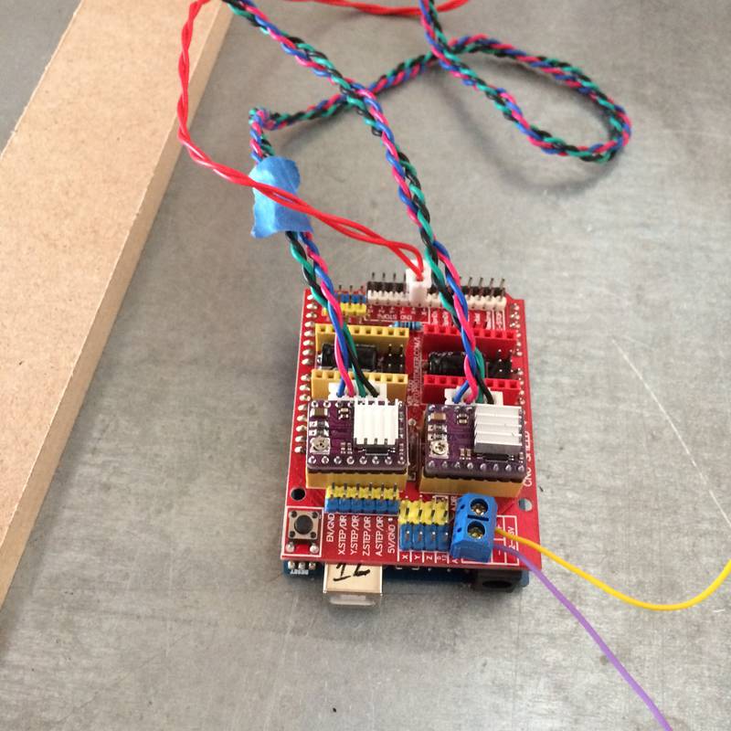
The karaoke machine control was done by an Arduino Uno with a CNC motor shield. See them here:
The shield has space for four motor drivers. You can see that we have two plugged in (the purple units). The twisted wires plugged in just beside the drivers are the wires to the motors. The purple and yellow wires leading offscreen are leading to a power supply, powering the motors. The shield has each driver's STEP and DIR pins wired to specific pins of the arduino. The microstep options that are normally selected by connecting to pins on the motor driver (M0, M1, and M2 in the schematic above on this page) are set by using jumpers on the board.
When I arrived at the Waag the next day Emma gave us the motor shield and an Arduino. I set the current limits on the motor drivers, but had problems setting it for anything other than a single shield. When I tried to measure on other shields, the voltage measurement from VREF simply would not change. After consulting Emma, she suggested that the power supply was not set to supply enough current, so I bumped the current supply to 1.2A, and it worked.
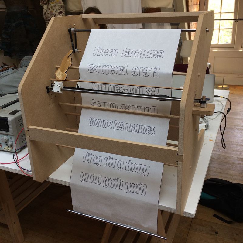
Eventually, both motors worked. They moved. We did a test of moving the hand motor one full turn and measuring the distance travelled. 4 cm per 200 steps. So 50 steps, one-quarter turn, per cm. To test, we pulled the hand all the way to the left and made the motor turn 1000, and sure enough it arrived almost at the centre of the bar.
I guessed that this travel distance was the same for the scroll motor, since it was using the same size gears, and we are talking about linear distance from a rotating motor. It turned out to be true. We tested lyric lines of 3 cm, and 150 steps was the right amount to turn for each line of lyrics.
The final code is not terribly different from the source code. There is still the step() function, and we can specificy which motor, and how many steps. At the moment, you specify the steps, not the distance or anything like that. I would have liked to have done it kind of like gcode, where you tell it what coordinates to go to and it would interpolate. I think Dima's working of the code did something similar.
Xavier attached the end stop to the left side of the machine, so that the hand mount would trigger it. I created a function to repeatedly move the motor until the button was triggered. It worked on the first try (yay!).
Here is the final code, as it was sent to Dima for finessing:
/* Fab Academy Karaoke machine
 *  David McCallum, Xavier Klein, Dima Paley, 2018
 *  sintheta.org
 *  Code adapted from http://aconcaguasci.blogspot.nl/2016/11/arduino-cnc-shield-control-stepper.html
 *
 * For both X and Y, 50 steps per cm
 *
 *
  *//


// Motor stuff
const int ENABLE = 8 ;

const int  motorX_DIR   =  5;  //Direction pin
const int  motorX_STP    = 2;  //Step pin

const int  motorY_DIR   =  7;  //Direction pin
const int  motorY_STP   = 4;  //Step pin

const int endstopPinX = 9;

//Driver Timing
int delayTime=450; //Delay between each pause (uS)

int musicPulse = 300;     // music timing pulse for the frere jacques functions


void setup(){

//  serial.begin(9600);

  pinMode(motorX_DIR, OUTPUT); pinMode(motorX_STP, OUTPUT);
  pinMode(motorY_DIR, OUTPUT); pinMode(motorY_STP, OUTPUT);

  pinMode(ENABLE, OUTPUT);
  digitalWrite(ENABLE, LOW);

  pinMode(endstopPinX, INPUT_PULLUP);


  goHome();         // zero the motor to the edge

  delay(2000);      // pause

  frBackwards() ;   // Play the song


}

void loop(){

}


// The basic move function
void step(boolean dir, byte dirPin, byte stepperPin, int steps){

  digitalWrite(dirPin, dir);

  for (int i = 0; i < steps; i++) {
    digitalWrite(stepperPin, HIGH);
    delayMicroseconds(delayTime);
    digitalWrite(stepperPin, LOW);
    delayMicroseconds(delayTime);
  }
}


// Move the motor until the endstop is reached
void goHome() {

  while (digitalRead(endstopPinX) == HIGH) {            // if the button isn't pressed, move the motor 1 step
    step(false, motorX_DIR, motorX_STP, 1);
    delayMicroseconds(delayTime);
  }

  step(true, motorX_DIR, motorX_STP, 50);

}


// play Frere Jacques with alternating lines moving backwards (because the motor couldn't rewind fast enough)

void frBackwards() {

  step(true, motorX_DIR, motorX_STP, 185);
  delay(musicPulse);

  for (int x = 0; x < 2 ; x++) {
    step(true, motorX_DIR, motorX_STP, 215);
    delay(musicPulse);
    step(true, motorX_DIR, motorX_STP, 220);
    delay(musicPulse);
    step(true, motorX_DIR, motorX_STP, 220);
    delay(musicPulse);

    step(true, motorY_DIR, motorY_STP, 150);
    delay(musicPulse);


    step(false, motorX_DIR, motorX_STP, 220);
    delay(musicPulse);
    step(false, motorX_DIR, motorX_STP, 220);
    delay(musicPulse);
    step(false, motorX_DIR, motorX_STP, 215);
    delay(musicPulse);

    step(true, motorY_DIR, motorY_STP, 150);
    delay(musicPulse);

  }


}


// Try Frere Jacques forwards for 4 lines
void fourLinesFR() {


  for (int x = 0; x < 4; x++) {

  step(true, motorX_DIR, motorX_STP, 185);
  delay(musicPulse);
  step(true, motorX_DIR, motorX_STP, 215);
  delay(musicPulse);
  step(true, motorX_DIR, motorX_STP, 220);
  delay(musicPulse);
  step(true, motorX_DIR, motorX_STP, 220);


  step(true, motorY_DIR, motorY_STP, 150);

  step(false, motorX_DIR, motorX_STP, 935);

  }

}
And here is our lovely machine in action! (again, before Dima's finessing)
