FABACADEMY
Embedded Programming
Welcome to my week 9
Embedded Programming
Learning Outcomes:
Brief
My Assignment:-
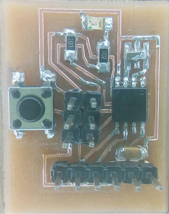
Program a Hello World Broad
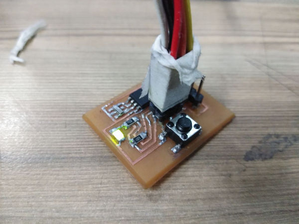
This is my Hello Board which I designed in Electronics week.
So I downloaded the Atmel studio software to program my Hello Board.
Atmel studio
Studio 7 is the integrated development platform (IDP) for developing and debugging all AVR® and SAM microcontroller applications. The Atmel Studio 7 IDP gives you a seamless and easy-to-use environment to write, build and debug your applications written in C/C++ or assembly code.
step 1: - Configure Atmel Studio
I need to configure Atmel Studio for each microcontroller that you I to program. Under the Tools menu, I clicked on External Tools
I Clicked Add and enter the following:
I got this type of window so I changed the specs because am using attiny 45
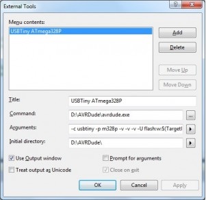
I used this type of arugument for attiny 45 given below
-c usbtiny -p attiny45 -v -v- -v -u flash:w:$(TargeDir)$(TargetName).hex:i
-c parameter specifies the programmer being used
-p parameter specifies the microcontroller (search the avrdude.conf file to find this).
-v parameters make sure the output is verbose, so I can check if anything goes wrong
the $(TargetDir) and $(TargetName) are Atmel Studio variables pointing to the project folder and the hex filename
and then for initial path I gave the path Avrdude
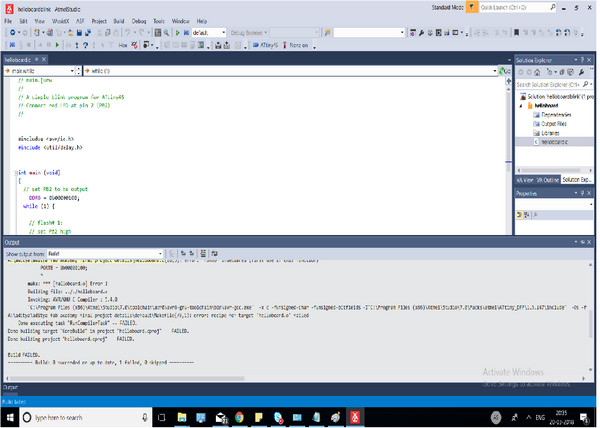
This is my code given below:-
Code
// main.[urw
//
// A simple blinky program for ATtiny45
// Connect red LED at pin 2 (PB2)
//


#includue < avr/io.h>
#include < util/delay.h>


int main (void)
{
  // set PB2 to be output
	DDRB = 0b00000100;
  while (1) {

    // flash# 1:
    // set PB2 high
    PORTB = 0b00000100;
    _delay_ms(1000);
    // set PB2 low
    PORTB = 0b00000000;
    _delay_ms(1000);

  }
}
- File’s Name in the source folder : blink.ino
Step 2 :- Program the AVR Microcontroller
Now I am ready to upload the program.
I Pluged in my controller and connected the ICSP connector to the board header.
Clicked Tools, then the title of my configuration from above USBTiny attiny 45
The program should upload and the AVR should start doing its thing.
so after along try it was not working.
I have to try it again
Getting started with Arduino IDE
Before starting to program our board using Arduino IDE, we need to tell the software that we'll be using a thrid party hardware i.e AVR ATTINY 44/45 etc........ For this we need to go to the Board Manager and add additional boards.....
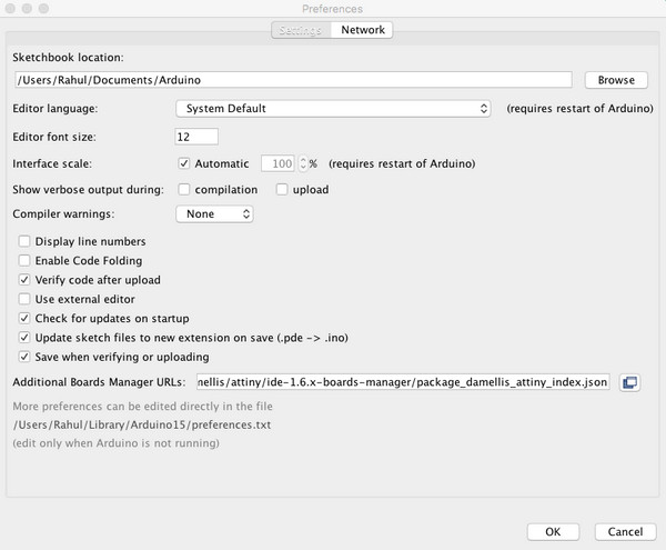
Steps to add additional boards
1. Go to Arduino Preferances and there in the text field add a link https://raw.githubusercontent.com/damellis/attiny/ide-1.6.x-boards-manager/package_damellis_attiny_index.json then click ok
2. Then go to the boards manager and install new board files as required.
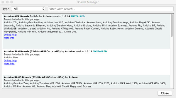
3. Now goto tools then to Boards and select the Microcontroller which you are using, in my case it was attiny 44 with 20Mhz external clock and programmer as USBTINY.
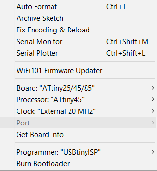
4. After this we need to burn the bootloader onto the chip, this step sets the fuses and flashes any previous configration over the chip.
Now, all set to write the program and dump it onto the chip
I edited code in this way.
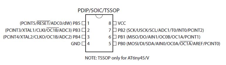
But before doing that we should always read the data sheet of the chip we are using ....... or atleast you should know the pin diagram of the chip you are using .....
Code
void setup() {

  pinMode(2, OUTPUT);
}

void loop() {
  digitalWrite(2, HIGH);
  delay(1000);
  digitalWrite(2, LOW);
  delay(1000);
}
So I can program now
So first I verify the code and then compiled the code to my board
After the code complied it shows done compiling
The LED start blinking
Button to Trigger LED
- Now i have to connect a button which will trigger the LED.
- Pull up the button pin internally.
Code
void setup() {

// initialize digital pin 8 as an output.
pinMode(3, OUTPUT);
pinMode(4,INPUT);
digitalWrite(4,HIGH); // internal pullup

}

// the loop function runs over and over again forever
void loop() {

if (digitalRead(4)){
digitalWrite(3, LOW);   // turn the LED on (HIGH is the voltage level)

}
else {

digitalWrite(3, HIGH);    // turn the LED off by making the voltage LOW

}
}
- File’s Name in the source folder : button.ino
- Working Video :
Download .ino files .................
// main.[urw
//
// A simple blinky program for ATtiny45
// Connect red LED at pin 2 (PB2)
//
#includue < avr/io.h>
#include < util/delay.h>
int main (void)
{
// set PB2 to be output
DDRB = 0b00000100;
while (1) {
// flash# 1:
// set PB2 high
PORTB = 0b00000100;
_delay_ms(1000);
// set PB2 low
PORTB = 0b00000000;
_delay_ms(1000);
}
}
- File’s Name in the source folder : blink.ino
Getting started with Arduino IDE
Before starting to program our board using Arduino IDE, we need to tell the software that we'll be using a thrid party hardware i.e AVR ATTINY 44/45 etc........ For this we need to go to the Board Manager and add additional boards.....
Steps to add additional boards
1. Go to Arduino Preferances and there in the text field add a link https://raw.githubusercontent.com/damellis/attiny/ide-1.6.x-boards-manager/package_damellis_attiny_index.json then click ok
2. Then go to the boards manager and install new board files as required.
3. Now goto tools then to Boards and select the Microcontroller which you are using, in my case it was attiny 44 with 20Mhz external clock and programmer as USBTINY.
4. After this we need to burn the bootloader onto the chip, this step sets the fuses and flashes any previous configration over the chip.
Now, all set to write the program and dump it onto the chip
I edited code in this way.
But before doing that we should always read the data sheet of the chip we are using ....... or atleast you should know the pin diagram of the chip you are using .....
void setup() {
pinMode(2, OUTPUT);
}
void loop() {
digitalWrite(2, HIGH);
delay(1000);
digitalWrite(2, LOW);
delay(1000);
}
So I can program now
So first I verify the code and then compiled the code to my board
After the code complied it shows done compiling
The LED start blinking
Button to Trigger LED
- Now i have to connect a button which will trigger the LED.
- Pull up the button pin internally.
void setup() {
// initialize digital pin 8 as an output.
pinMode(3, OUTPUT);
pinMode(4,INPUT);
digitalWrite(4,HIGH); // internal pullup
}
// the loop function runs over and over again forever
void loop() {
if (digitalRead(4)){
digitalWrite(3, LOW); // turn the LED on (HIGH is the voltage level)
}
else {
digitalWrite(3, HIGH); // turn the LED off by making the voltage LOW
}
}
- File’s Name in the source folder : button.ino
- Working Video :