Welcome to my week 6
3D Printing and Scanning:
Learning Outcomes:
Learnt how to use 3D SCANNER
Using ultimaker and Makerbot.
ACHIEVEMENTS THIS WEEK:
3d Printing
1. Introduced to FDM
2. Printed with an FDM printer.
3D Scanning
1. Introduced to xbox 360 (Kinect)
2. GEOPhotographic 3d Scanning Technique
IDEAS THIS WEEK:
Brief
Xbox 360 (Kinect):-
The Xbox One's Kinect, a motion controller peripheral for the console. The Kinect uses a multiple camera types and microphones to let a user control the xbox with motion and sound.
U can Download the software Here
3D Printer (MAKERBOT REPLICATOR Z18):-
Massive Build Volume for the Professional Innovator. The MakerBot Replicator Z18 makes solid, three-dimensional objects out of melted MakerBot PLA Filament. First, use MakerBot Desktop to translate 3D design files into instructions for the MakerBot Replicator Z18. Then transfer those instructions to the MakerBot Replicator Z18 via USB drive, USB cable, ethernet, or Wi-Fi. The MakerBot Replicator Z18 will melt MakerBot PLA Filament and squeeze it out onto the build plate in thin lines to build your object layer by layer. With the huge build volume of the MakerBot Replicator Z18, this part of the process can take a long time. The method of 3D printing used by the MakerBot Replicator Z18 is called fused deposition modeling.
Group Assignment
Getting started with 3D printing.
Printing test parts to test MakerBot's design rules
As Neil had explained during class that before we print anything on a 3D printer, we must test its design rules. In other words, we must know our printer's capabilities and limitations. We printed test parts for the following tests so far:
1. Bridge test: This test was performed to find out the length of the longest beam on two pillars (at the beam's ends) that can be printed without any supports in-between. To do so, we printed a test part with beam length varying from 10 mm (1 cm) to 100 mm (10 cm). Unfortunately, when we started printing this (and other test parts), we did not realize until a lot later in the process (almost towards the end) that MakerBot's software's default setting for "supports" is ON. Hence, our test part printed out with supports under the beams, and so, we couldn't really conclude anything from this test. The test part needs to be re-printed.

2. Overhang test: To test what angles can be made without any support on the MakerBot, we printed a test part with 5 different overhangs (angles): 80 degree; 60 degree; 40 degree; 25 degree; and 15 degree. We found out that our printer can easily make parts that have overhangs of 80 degree, 60 degree, and 40 degree without any support and with a smooth overhang surface. This was not true for smaller angles, though. At 25 degree, it printed the overhang without any support, but with a rough, unfinished-looking surface. At around 15 degree, the overhang could not be printed without support.

3. Wall thickness test: To test what what thicknesses can be printed on the MakerBot, and will also be mechanically strong, we printed a test part with 5 different wall thicknesses: 2 mm, 1 mm, .75 mm, .5 mm, and .25 mm. We found out that all wall thicknesses printed, turned out to be strong, and none shredded. Obviously, walls with 2 mm thickness were stronger than walls with .25 mm thickness, with strength decreasing from the thickest to the thinnest walls.

4. Orientation test: We tested how we should orient a part to print it. For this, we printed the same object in 3 different orientations/ways: varying the contact surface each time. We learnt that larger the contact surface area between the part and the raft, the better it is. Our test part was in the shape of the letter "L." When printed lying flat (maximum contact surface); and when oriented vertically up (relatively lesser contact surface), the parts turned out fine, and with good structural integrity. However, when the "L" was oriented upside down (least contact surface), and with a 90 degree overhang, it had to be supported. But, then the "support" feature was ON. So, we can not conclude anything about printing in this orientation (with the lease contact surface). This last part needs to be re-printed.

5. Holes test: This test was performed to check what is the smallest hollow cylinder that can be printed on the MakerBot. We printed a test part with hollow cylinders with internal diameter ranging from 3 mm to less than 1 mm. We learnt that for cylinders below approximately 1 mm internal diameter, their lateral surfaces coalesced, but with diameters greater than 1 mm, the hollow cylinders printed out intact. This test also told us something about another test: At what distance from each-other, 2 printed dots don't coalesce. Dots printed approximately 1 mm apart or less will coalesce on our printer.

STEPS Followed for 3D Printing:
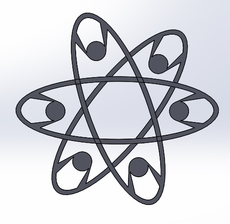
Gyroscope Spinner
I thought to make an fidget spinner on 3d printer but my fidget spinner should not be made by subtractively. so I added a gyroscope in the cetre because gyroscope can't be abble to make by subtravtively.
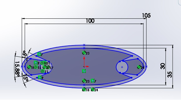
Designed file in 3D. After calculating length, height, thickness. I basically designed in Solidworks ,I want to make sure that its not subtractive, it can be simple functional item too. Therefore, it seems simple but it took me lot of time bringing that curve/bent to the right dimension in the right positon.
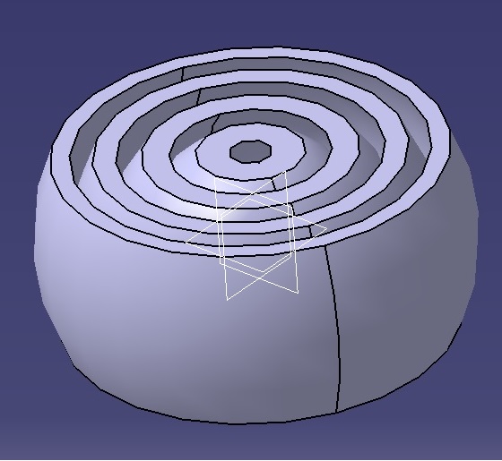
STEP 1: I just disgined and I gave the dimension
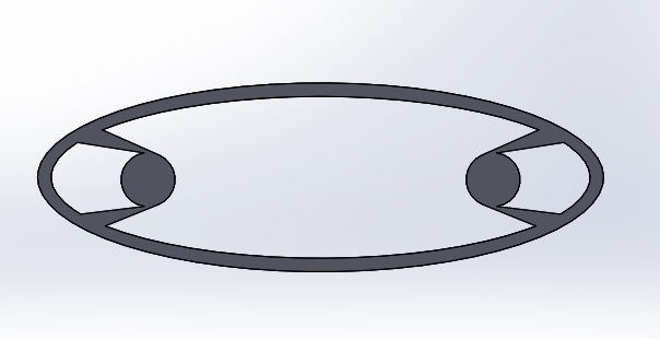
STEP 2: I excruded the model
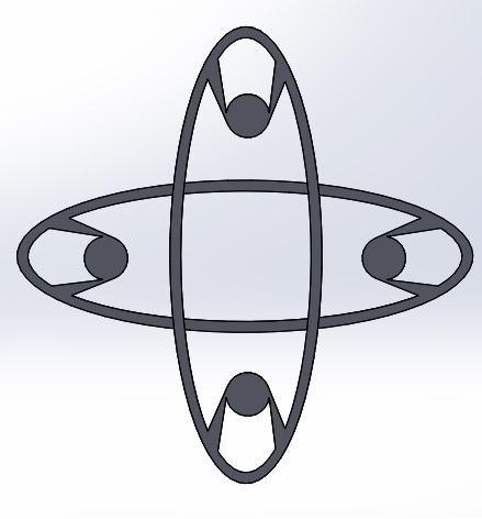
STEP 3: I assembled the parts.
Export in STL. I used a plugin called .STL from extension warehouse of Solidworks.
While designing the Gyroscope, I just made 4 rings in Gyroscope of different diameters so that it can fit inside each other and so that it should not come out of each other I made the Rings a bit curvy, you can see it below in the screenshot of the design.
WHY IT CAN'T BE MADE SUBTRACTIVELY?
It was not possible to make it subtractively because its having 4 Rings interlocked one inside another which is not possible for any machine to make it just by subtracting the material. Even subtractively it can't be made moveable or rotatary one inside the other, thats the main reason that I am making it in additive manufacturing process.
Its time to print.
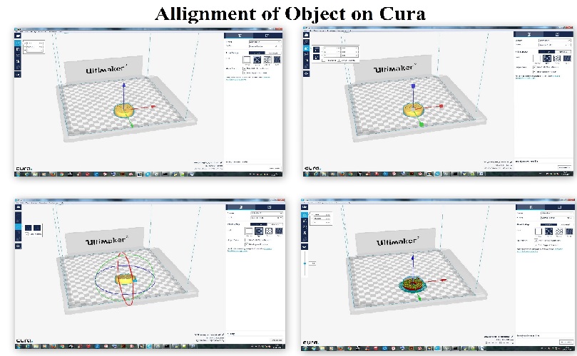
I printed all the models on the MakerBot Replicator Z18 because our Ultimaker has a problem in excruding the ABS material.
So first I tried in ultimaker so I used cura software but the excrudder is not working that's why I used Makerbot.
U can Download the software Here
Download .sld file
I used MakerBot print for MakerBot Replicator Z18.
Step 1: First off all i imported the .stl file in MakerBot print.
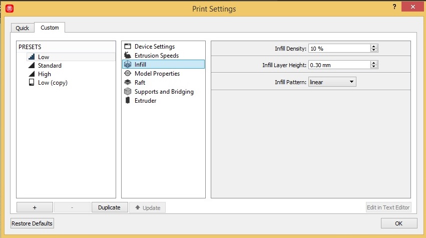
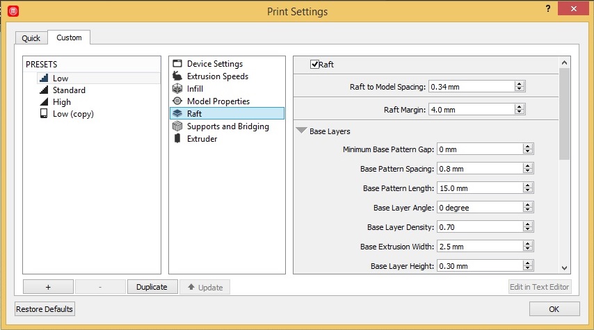
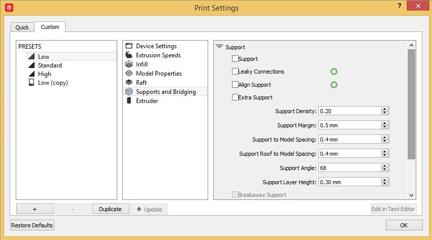
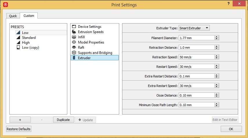
Step 2: There are few important steps which are really helpfull for the model to print. we have to set before we print... Those are:- Infill, Raft, Support and Bridging, Extruder, Device settings.
Step 3: After importing the .stl file then I switched of the support in the software because if the support is on then it wont work properly.
Step 4: And then I used all the default settings.
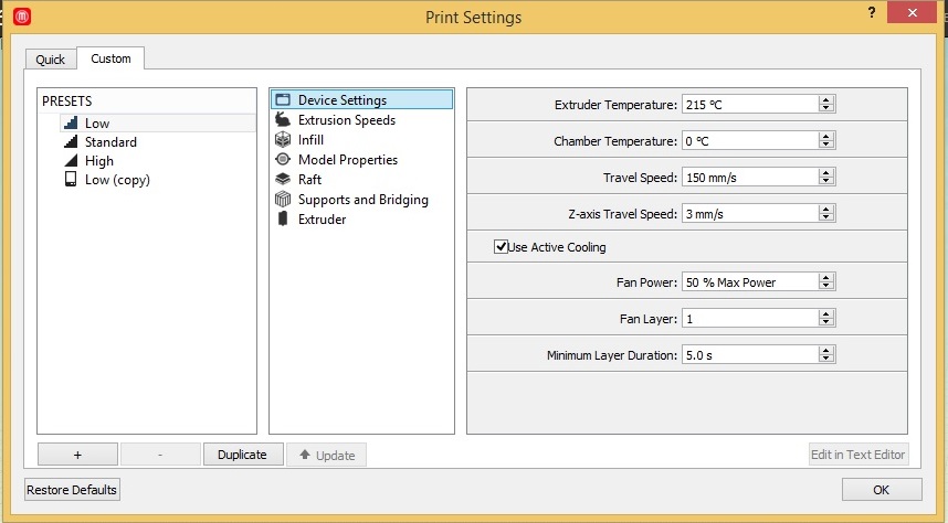
Step 5: Default setting pics are given below..
Pic 1: Device settings
Pic 2: Infill
Pic 3: Raft
Pic 4:Support and Bridging
Pic 5: Extruder
After all this you should see the preview of your model.
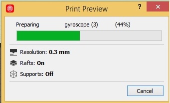
After this I exported my file to (*.makerbot) So my file is converted in a gcode.And then I can print on MakerBot Replicator Z18.
.So My file is reddy to print.
In MakerBot Replicator Z18 there are three steps :-
Step 1: Heating extruder- approx 160c to 180c
Step 2: Moving Into Position
Step 3: Final heating - 180c to 215c
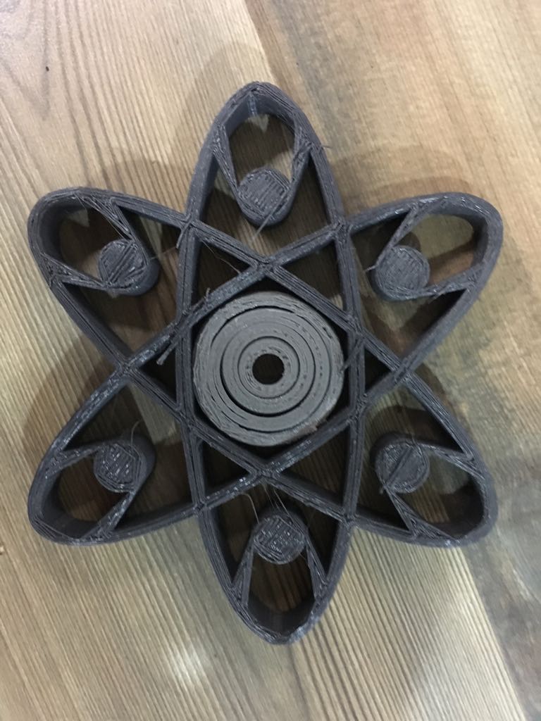
This is my final product which I printed on MakerBot Replicator Z18.
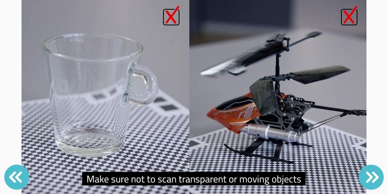
3D scanning.
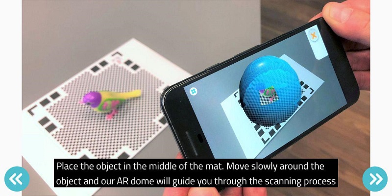
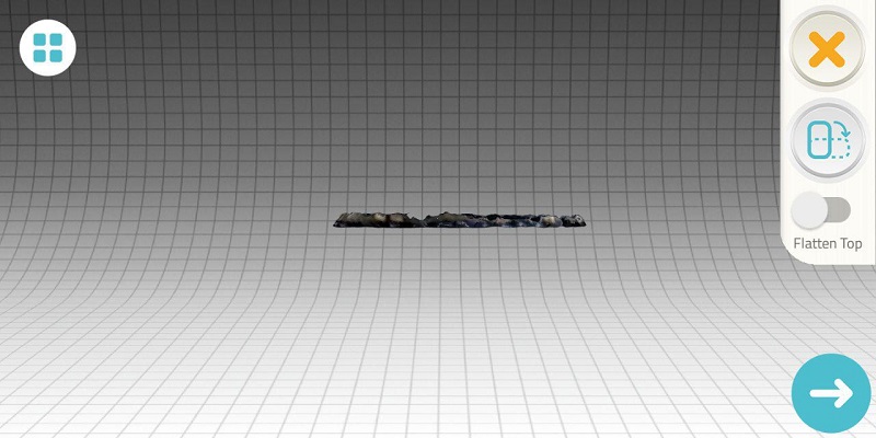
I have used QLONE software

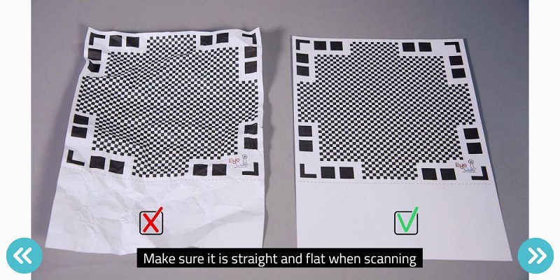
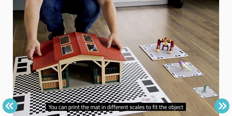
Note: Mat is very important thing in the whole process as Mat provides referance points to the App.
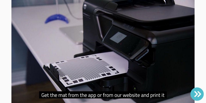
Print the scanning mat Its very important that you print the scanning mat completely with all the edges..
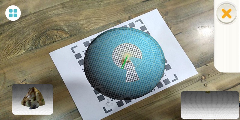
After all this setup kinda things we are good to go
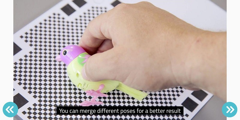
Here is my Experience with 3D Scanning
fellow the steps......