FABACADEMY
computer-controlled cutting
Welcome to my week 4
Laser Cutting:
Press Fit
Vinyl Cutting:
Just Normal photoshop design
Laser Cutting
Brief
For more info about group assginment - click here.
I wanted to make a Photo Album

Process
First i downloaded RDworks and started designing in RDworks software
u can design this in Solidworks or autodesk software.
I just tried in RDworks..
U can Download software Here

This is my basic design

In this way i did press fit for my album


2. I engraved my face on MDF and acrylic.
First i choosed a pic of mine and then i converted my pic into .bmp

and then i imported the .bmp file to RD CAM {RD WORKS} and i gave the min power: 80, max power: 85, and speed: 60.and started printing.

this looks like this...

3. vinyl cutter.
A vinyl cutter is a type of computer-controlled machine. Small vinyl cutters look like computer printers. The computer controls the movement of a sharp blade like a knife. This blade is used to cut out shapes and letters from sheets of thin self-adhesive plastic (vinyl).
A symbol / label can be produced using a Vinyl Cutter such as a ‘Sticker Machine’ or a ‘Craftrobo’. These machines are controlled by a computer and operate similar to a printer. Essentially they cut out shapes in adhesive vinyl. The vinyl can then be stuck onto almost any surface.
A vinyl cutter (or vinyl plotter) is a computer-controlled plotting device with a blade instead of a pen. A vector based design is created in a software program (usually Adobe Illustrator or Corel Draw) and then sent to the cutter where it cuts along the vector paths laid out in the design. The cutter is capable of moving the blade on an X and Y axis over the material, cutting it into any shape imaginable. Since the vinyl material comes in long rolls, projects with significant length like banners or billboards can be easily cut as well. The one major limitation with vinyl cutters is that they can only cut shapes from solid colours of vinyl. A design with multiple colours must have each colour cut separately and then layered on top of each other as it is applied to the substrate. Also, since the shapes are cut out of solid colours, photographs and gradients cannot be reproduced with a stand alone cutter.
In addition to the capabilities of the cutter itself, the adhesive vinyl comes in a wide variety of colours and materials including gold and silver foil, vinyl that simulates frosted glass, holographic vinyl, reflective vinyl, thermal transfer material, and even clear vinyl imbedded with gold leaf. (Often used in the lettering on fire trucks and rescue vehicles.)
so downloaded some pics and i mixed all the pics in photoshop.
I did this cutting because u can see a name on the pic that means the meaning of that word (vynatheya) is Eagle so thats y i mixed my name in Eagle....

After my editing i opened this .jpg file in Graphtec Studio..
There are so many types of extension in Graphtec Studio pic given below..

so I opened .jpg file in Graphtec Studio.......

Open the trace window.

Select the trace window

I slected trace

There are three types of traces
I saparated the original from the trace and delect it


My design is reddy to print ....

Machine started working

After cutting I removed the sticker out and i used a transprent tape to stick on my laptop.
weed:- Remove an inferior or unwanted component of a group or collection. so I removed my outside layer to stick on my laptop..

This is the final pic of my design that I sticked on my laptop
.jpg)

Download .bmp file
Parametric Press Fit Construction Kit
This week's assignment was not very much clear for me I am bit confused what to make So I ended up with making basic shapes with some PRESS FIT arrangement.
So I started with making a shape using the Solidworks, then I played along with the tools, like trimming, making , mirroring, veiw etc.
Linking Dimensions Using Global Variables
To link values by using a global variable in the Modify dialog box:
-
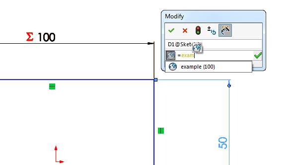
Double click the dimension, then in the Modify dialog box, type = (equal sign).

You must enter the equal sign to assign a global variable to the dimension. If you do not enter the equal sign, you can create a new global variable, but it will not be assigned to the dimension.
- Type a name for the global variable.The name appears in yellow and Create Global Variable appears.

- Click Create Global Variable
 .
.
- Click
 .
.  appears next to the dimension in the graphics area.
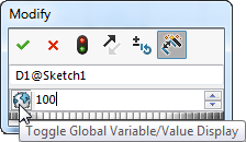
- Toggle the display of the value and the name by clicking the Global Variable button
 .
.
-
Find the dimension you want to associate with the global variable. Double click the dimension, then in the Modify dialog box, type = (equal sign) and several characters of the global variable name.
A flyout menu appears with a name that matches the characters you have typed.
- Select the global variable name and click .Both dimensions become linked to the global variable.
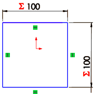
You can edit the global variable by double clicking the dimensions and using the Modify dialog box, or by editing the values in the Equations dialog box.Global variables are bi-directional, meaning that if two or more dimensions are defined in terms of a global variable, then changing any one of the dimensions will cause the others to change.
So In this way I have used variables in Solidworks like if I change the one variables it changes the total design and per the variable.
So I got a cardboard sheet which i can cut my design and test so the tickness of the cardboard is arround 3.08 mm
So I took 3mm of each side because mu KERF is 0.3 mm .
.png)
Cutting Parametric design on laser cutter
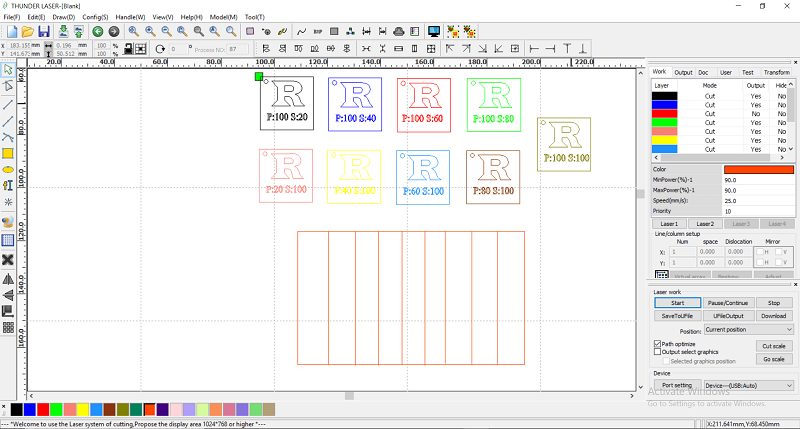
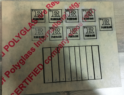
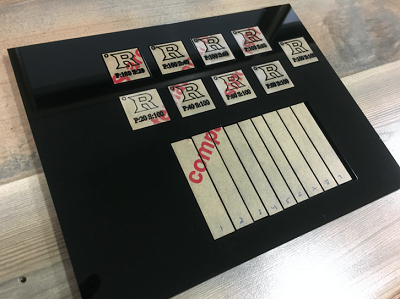
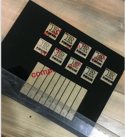
using laser works v6 software for laser cutting.
The power and speed combination I used was P:90 Speed : 40 . Actually
, I have calculated the kerf accurately but since the base of Our LASER Cutter was not leveled I used to give multiple passes to get the final cutout.
.png)
Finnaly it looks like this.
.jpeg)
.jpeg)
Download Parametric design files .................
To link values by using a global variable in the Modify dialog box:
-
Double click the dimension, then in the Modify dialog box, type = (equal sign).
You must enter the equal sign to assign a global variable to the dimension. If you do not enter the equal sign, you can create a new global variable, but it will not be assigned to the dimension. - Type a name for the global variable.The name appears in yellow and Create Global Variable appears.
- Click Create Global Variable
- Click
- Toggle the display of the value and the name by clicking the Global Variable button
-
Find the dimension you want to associate with the global variable. Double click the dimension, then in the Modify dialog box, type = (equal sign) and several characters of the global variable name.
A flyout menu appears with a name that matches the characters you have typed.
- Select the global variable name and click Both dimensions become linked to the global variable.
Global variables are bi-directional, meaning that if two or more dimensions are defined in terms of a global variable, then changing any one of the dimensions will cause the others to change.
So In this way I have used variables in Solidworks like if I change the one variables it changes the total design and per the variable.
So I got a cardboard sheet which i can cut my design and test so the tickness of the cardboard is arround 3.08 mm
So I took 3mm of each side because mu KERF is 0.3 mm .
Cutting Parametric design on laser cutter
using laser works v6 software for laser cutting.
The power and speed combination I used was P:90 Speed : 40 . Actually , I have calculated the kerf accurately but since the base of Our LASER Cutter was not leveled I used to give multiple passes to get the final cutout.
Finnaly it looks like this.